Table of Contents
Advertisement
Quick Links
Advertisement
Table of Contents

Subscribe to Our Youtube Channel
Related Manuals for Wood-mizer LT40 MH Series


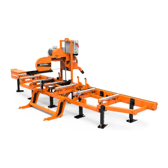
Summary of Contents for Wood-mizer LT40 MH Series
- Page 1 EA25 Motor Safety, Operation, Maintenance & Parts Manual LT40 Series MH rev. D5.03 LT40 Series AH rev. D5.03 Safety is our #1 concern! Read and understand all safety information and instructions before oper- ating, setting up or maintaining this machine. November 1998 Form #972...
-
Page 2: Table Of Contents
Table of Contents Section-Page SECTION 1 SAFETY & GENERAL INFORMATION Motor Operation ......................1-1 Electrical Operation....................1-1 SECTION 2 OPERATION Starting The Motor ....................2-1 SECTION 3 MAINTENANCE Drive Belt Adjustment....................3-1 SECTION 4 REPLACEMENT PARTS How To Use The Parts List ..................4-1 Sample Assembly ...................... -
Page 3: Safety & General Information
This manual is provided as a supplement to the equip- ment manufacturer’s manuals. This manual takes into account the specific use of engines on the Wood-Mizer sawmill. Only safety, main- tenance, and operating procedures that are not provided by the manu- facturer are supplied in this manual. - Page 4 Safety & General Information Electrical Operation Safety & General Information EA25doc040611...
-
Page 5: Operation
Operation Starting The Motor SECTION 2 OPERATION Starting The Motor Control Box RYS. 2-0 Operation EA25doc040611... - Page 6 Operation Starting The Motor Motor Start IMPORTANT! When starting the machine for the first time, check that main motor rotation direction is as indicated by the arrow located on the motor body (fan guard). If the rotation direction is incorrect, invert the phases in the phase inverter located in the power socket (electric box).
-
Page 7: Maintenance
Maintenance Drive Belt Adjustment SECTION 3 MAINTENANCE This symbol identifies the interval (hours of operation) which each maintenance procedure should be performed. "AR" signifies maintenance procedures which should be performed as required. Drive Belt Adjustment Periodically check all belts for wear. Replace any damaged or worn belts as needed. DANGER! Do not for any reason adjust the drive belt support with the motor running. -
Page 8: Replacement Parts
+48-63-2626000 or +48-3912-1319. From the continental U.S., call 1-800-448-7881 to order parts. Have your customer number, vehicle identification number, and part numbers ready when you call. From other international locations, contact the Wood-Mizer distributor in your area for parts. EA25doc040611 Replacement Parts... -
Page 9: Motor Starter Assembly
Replacement Parts Motor Starter Assembly Motor Starter Assembly AC0021 DESCRIPTION Indicates Parts Available In Assemblies Only) PART # QTY. Box, AC Super Electric Motor Starter 098736 Connector, GP29 Click 6180 0910 086576 Bolt, M8 x 30-8.8-B Hex Head F81002-7 Nut, M8-8-B Hex F81032-1 Controller, ATV31HU11M2 220V/1.5kW Electric Motor Speed 093487... -
Page 10: Motor Assembly
Replacement Parts Motor Assembly Motor Assembly 3H0001P DESCRIPTION Indicates Parts Available In Assemblies Only) PART # QTY. ELECTRIC ASSY ENGINE 18,5KW, AC SUPER EA25 MOTOR, 18.5 KW/380V 1LA7166-2AA60-Z 087397 MOTOR, 1LA7166-2AA10-Z G26 ELECTRIC ( NORWAY ONLY) 087397-2 PLATE, E25 ENGINE MOUNT 086801-1 PULLEY, 15/18,5KW ELECTRIC MOTOR 085671... -
Page 11: Motor Pulley Guards, Ea25
Replacement Parts Motor Pulley Guards, EA25 Motor Pulley Guards, EA25 3H0673P2 DESCRIPTION Indicates Parts Available In Assemblies Only) PART # QTY. COVER, E20/E25 MOTOR UPPER 087059-1 BRACKET, E25 BELT SUPPORT UPPER 085865-1 REST, BELT DRIVE LOWER 085922-1 Replacement Parts EA25doc040611... -
Page 12: Power Cord Bracket
Replacement Parts Power Cord Bracket Power Cord Bracket 3h0492 DESCRIPTION Indicates Parts Available In Assemblies Only) PART # QTY. BRACKET, POWER CORD PTD 091813-1 Power Cord Bracket, LT40B 3h0493 DESCRIPTION Indicates Parts Available In Assemblies Only) PART # QTY. BRACKET, LT40B POWER CORD COMPLETE 504309 GROMMET, RUBBER 087065... - Page 13 Replacement Parts Power Cord Bracket, LT40B EA25doc040611 Replacement Parts...
-
Page 14: Brake Air Gap Adjustment
Brake air gap adjustment SECTION 5 BRAKE AIR GAP ADJUSTMENT To ensure proper operation of the brake, it is necessary to set correctly the air gap between the armature and the electromagnet. Each time the brake is installed or the brake subassemblies are replaced or the motor overheats or the brake is inspected (the inspection should be performed at least every six months), check and, if necessary, adjust the brake air gap. - Page 15 Brake air gap adjustment Table 1 Paramet “a” 0,20 0,20 0,20 0,30 0,30 0,30 0,30 0,30 0,40 nom. “a” 0,50 0,50 0,50 0,70 0,80 1,00 1,20 1,20 1,40 max. To adjust the air gap, perform the following steps : - Dismount the motor casing, - Remove the brake casing (7), - Loosen the mounting bolts (6) half a turn using an adequate allen wrench (see wrench sizes in Table 2), Table 2...
Need help?
Do you have a question about the LT40 MH Series and is the answer not in the manual?
Questions and answers