Table of Contents
Advertisement
Quick Links
Advertisement
Table of Contents

Related Manuals for Wood-mizer LT40 AH Series


Summary of Contents for Wood-mizer LT40 AH Series
- Page 1 Table of Contents Section-Page Table of Contents SW-07doc0328171...
- Page 3 Wood-Mizer Sawmill ® Safety, Setup, Operation & Maintenance Manual LT40 Series AH rev. E1.01 LT40 Series AH WIDE rev. E1.01 Safety is our #1 concern! Read and understand all safety information and instructions before operating, setting up or maintaining this machine.
- Page 4 *Wood-Mizer is a registered trademark of Wood-Mizer Products, Inc. Sawmill and Customer Identification Each Wood-Mizer sawmill has a 17-digit Vehicle Identification Number (VIN). See the fig- ure below for VIN locations. See the chart for VIN description. HD0133 V.I.N. LOCATIONS.
- Page 5 F9 017 F9 .01 V.I.N. DESCRIPTION Each sawmill is also identified with a model number which includes the base model and the engine/motor configuration. See the figure for a description of the model number. LT40 Engine/Motor Basic Sawmill I.D. Configuration MODEL NUMBER DESCRIPTION.
- Page 6 HDSdoc030722...
-
Page 7: Table Of Contents
Table of Contents Section-Page SECTION 1 SAFETY & GENERAL INFORMATION Blade Handling..................1-2 Sawmill Setup..................1-2 Sawmill Operation..................1-3 Sawmill Maintenance ................1-6 Towing the Sawmill ................1-11 Belt Sizes ....................1-12 Blade Sizes ...................1-12 Cutting Capacity...................1-13 Motor Specifications ................1-13 1.10 Noise Level...................1-14 1.11 Overall Dimensions ................1-16 1.12 Chains ....................1-18 1.13... - Page 8 Table of Contents Section-Page SECTION 3 MAINTENANCE Wear Life....................3-1 Blade Guides ..................3-2 Sawdust Removal ...................3-3 Carriage Track, Wiper & Scrapers ............3-4 Vertical Mast Rails .................3-5 Drum Switches ..................3-5 Miscellaneous ..................3-5 Blade Tensioner..................3-6 Blade Wheel Belts ..................3-7 3.10 Drive Belt Adjustment................3-7 3.11 Hydraulic System ...................3-8 3.12...
- Page 9 Table of Contents Section-Page 5.16 Clamp Stop/Stop Bolt Adjustment ............5-28 5.17 Vertical Adjustment of Side Supports (Super Hydraulic Sawmill Only)5-29 5.18 Saw Head Tilt ..................5-30 5.19 Blade Height Scale Adjustment............5-31 SECTION 6 MOTOR BRAKE Motor Brake Maintenance..............6-1 Table of Contents SW-07doc0307223...
- Page 10 Getting Service Wood-Mizer is committed to providing you with the latest technology, best quality and strongest customer service available on the market today. We continually evaluate our customers’ needs to ensure we’re meeting current wood-processing demands. Your comments and suggestions are welcome.
- Page 11 Branches & Authorized Sales CentersWood-Mizer Locations (North and South America) EUROPE UNITED STATES European Headquarters World Headquarters Wood-Mizer Industries Sp. z o.o. Wood-Mizer LLC Nagórna 114, 62-600 Koło, Poland 8180 West 10th Street Tel.: +48-63-26-26-000 Indianapolis,Indiana 46214-2400, Fax: +48-63-27-22-327 www.woodmizer.eu Tel.: +1-317-271-1542...
- Page 12 CROATIA Krešimir Pregernik ITALY Pasquale Felice SERBIA Dragan Markov Pregimex d.o.o. Wood-Mizer Italia Srl Wood-Mizer Balkan d.o.o. S. Batušiæa 31, 10090 Zagreb Cda. Capoiaccio SN Svetosavska GA 3/3; P. Fah 25 Tel.:/Fax: +3851-38-94-668 86012 Cercemaggiore 23 300 Kikinda Krešimir Pregernik Campobasso Tel.:/Fax: +381-230-25-754...
- Page 13 Robert Moxham DENMARK Kevin Christiansen TRANSILVANIEI Nr. 5 Regional Direction - Asia Kevin Christiansen's Sibiu, Cisnadie 555300 Wood-Mizer Asia Manufacturing Co., Ltd. savværker PMV Tel.:/Fax: : +40-369-405-433 No.2, Gongyequ 40th Rd. Xitun District, Arnborgvej 40, 7330 Brande- Fasterholt GSM: +40-745-707-323 Taichung City, 40768, Taiwan, R.O.C.
-
Page 14: Safety & General Information
It is always the owner's responsibility to comply with all applicable federal, state and local laws, rules and regulations regarding the ownership, operation and towing of your Wood-Mizer sawmill. All Wood-Mizer mill owners are encouraged to become thoroughly familiar with these applicable laws and comply with them fully while using or towing the mill. -
Page 15: Blade Handling
Safety & General Information Blade Handling Blade Handling DANGER! Shut off the sawmill motor before changing the blade. Failure to do so will result in serious injury. WARNING! Always wear gloves and eye protection when handling bandsaw blades. Changing blades is safest when done by one person! Keep all other persons away from area when coiling, carrying or changing a blade. -
Page 16: Sawmill Operation
Safety & General Information Sawmill Operation Sawmill Operation IMPORTANT! The sawmill is intended for sawing wood only. Section 1.8 for log size capacities of the machine. IMPORTANT! The operator of the sawmill should get adequate training in the operation and adjustment of the machine. DANGER! Make sure all guards and covers are in place and secured before operating or towing the sawmill. - Page 17 Safety & General Information Sawmill Operation WARNING! Always leave loading arm halfway up while log is on sawmill bed. Failure to do so may result in serious injury or death. WARNING! The automatic board return is intended to assist a second operator in removing boards quickly.
- Page 18 Safety & General Information Sawmill Operation DANGER! Any arbitrary repairs of the electric installation could result in serious injury or death. DANGER! Any damaged electric parts, especially the wires supplying the power feed motors must be repaired by a qualified electrician. DANGER! Any repairs done to the electric installation may be done by a qualified electrician with the power off.
-
Page 19: Sawmill Maintenance
Safety & General Information Sawmill Maintenance CAUTION! Always wear gloves when handling the blade. Never grab the blade with bare hands! CAUTION! If the blade breaks during sawmill operation, push the EMERGENCY STOP button to stop the blade motor and wait 10 seconds before you open the blade housing cover. - Page 20 Safety & General Information Sawmill Maintenance CAUTION! Do not over-tighten the contact set screws on the hydraulic valve assembly. Over-tightening may cause the threads in the screw hole to strip. CAUTION! Due to variations in the vertical mast, the pad spacing may vary throughout the travel of the saw head.
- Page 21 Safety & General Information Sawmill Maintenance TABLE 1-1 099219 Blade tension. Turning the bolt clockwise will increase the blade tension and turning the bolt counterclockwise will decrease the tension. 099219 099223 Blade tension - See manual. 099223 099221 CAUTION! Keep all persons a safe distance away from work area when operating the machine.
- Page 22 Safety & General Information Sawmill Maintenance TABLE 1-1 096316 CAUTION! Do not open or close the electric box when the switch is not in the “0” position. 096319 CAUTION! Disconnect power supply before opening the box. 099222 CAUTION! Sawdust outlet. Protect eyes! 099542 CAUTION! Trailer.
- Page 23 Safety & General Information Sawmill Maintenance TABLE 1-1 512235 Clean chain from sawdust every 50 hours of operation or once a week 512235 512157 Lubricate chain every 50 hours of opera- tion or once a week. 512157 S12004G CAUTION! Always wear safety goggles when operating the sawmill! S12005G CAUTION! Always wear protective ear...
-
Page 24: Towing The Sawmill
Safety & General Information Towing the Sawmill TABLE 1-1 P11789 Aligning the blade on the wheels P85070 CE safety certification 099401 Russian safety certification 099401 S20097E 2930 RPM - Motor rotation direction 2930 RPM S20097E Towing the Sawmill CAUTION! Check if towing assembly is securely fastened. Always be sure that safety chains are secured. -
Page 25: Belt Sizes
Blade Sizes See Table 1-3. Wood-Mizer TRU•SHARP™ offers three types of blades to provide efficient sawing for all models of sawmills. The engine/motor size of your sawmill and the type of wood you saw should determine which blade you choose for optimum performance. -
Page 26: Cutting Capacity
Safety & General Information Cutting Capacity Cutting Capacity See Table 1-4. The log size capacities of the LT40 Series A H sawmills are listed below. Max. Max. Length Diameter LT40 S AH 36" (91.5 cm) 15' 7" (4.8 m) LT40 M AH 36"... -
Page 27: Noise Level
Safety & General Information Noise Level See Table 1-7. The power options available for the LT40 Series AH sawmills are listed below. Model Manufacturer Rated Current at Rated Speed Weight Output 380V, 50Hz 3Sg 160M-2B-HM-T Tamel SA, 15kW 28,1 A 2930 RPM 117 Kg Motor, Tamel... - Page 28 Safety & General Information Noise Level LT40AE20AH 78,0 dB (A) LT40AE25AH 86,2 dB (A) TABLE 1-10 1. The noise level measurement was taken in accordance with PN-EN ISO 3746 Standard. The noise exposure level given above concerns an 8-hour work day 2.The measured values refer to emission levels, not necessarily to noise levels in the workplace.
-
Page 29: Overall Dimensions
Safety & General Information Overall Dimensions 1.11 Overall Dimensions See Table 1-11. The overall dimensions of the Wood-Mizer LT40 Series AH sawmills are listed below. Model With Weight Length Width Height Weight (Operating Position w/Trailer with Loading Arms) LT40 S AH 21’... - Page 30 Safety & General Information Overall Dimensions See Figure 1-2. The LT40 S dimensions are shown below. FIG. 1-2 See Figure 1-3. The LT40 M Wide dimensions are shown below. FIG. 1-3 1-17 HDSdoc030722 Safety & General Information...
-
Page 31: Chains
Safety & General Information Chains 1.12 Chains See Table 1-12. The load capacity of the chains is listed below. Load Capacity According to ISO Nr 08A-1 Power Feed Chain 1780N Up/Down Chain 1780N TABLE 1-12 1.13 Hydraulic System See Table 1-13. The specifications of the hydraulic system are shown below. Hydraulic Pump HYDROIRMA Pressure Rating... -
Page 32: Dust Extractor Specifications
Safety & General Information Dust Extractor Specifications 1.14 Dust Extractor Specifications See Table 1-14. Specifications of the dust extractors used on the resaw for each saw head are listed below. Airflow 1200 m 3937ft Inlet diameter 100 mm (5.9”) Motor power 1,5 kW Number of sacks 1 pcs... -
Page 33: Components
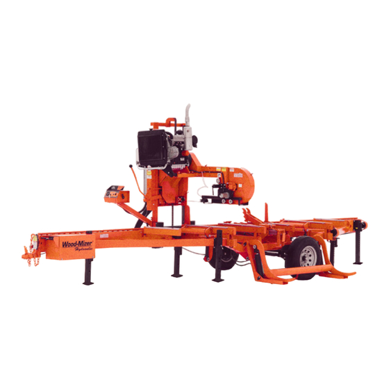
Safety & General Information Components 1.15 Components See Figure 1-4. The major components of the Wood-Mizer LT40 Series AH are shown below. Blade Drive Motor Assembly Cutting Head Control Blade Tensioner FIG. 1-4 Safety & General Information HDSdoc030722 1-20... -
Page 34: Setup & Operation
Setup & Operation Sawmill Setup SECTION 2 SETUP & OPERATION Sawmill Setup IMPORTANT! Before starting to use the sawmill you have to meet the following conditions: Set up the sawmill on firm, level ground and level the sawmill. Secure the sawmill to the ... - Page 35 Setup & Operation Sawmill Setup Portable Sawmill Stationary Sawmill Have a qualified electrician install the power supply (according to EN 60204 Standard). The power supply must meet the specifications given in the table below. See Table 2-1. 3-Phase Fuse Disconnect Suggested Wire Size Volts 400 VAC...
- Page 36 Setup & Operation Sawmill Setup IMPORTANT! When starting the machine for the first time, check that main motor rotation direction is as indicated by the arrow located on the motor body (fan guard). If the rotation direction is incorrect, invert the phases in the phase inverter in the power socket (electric box).
- Page 37 Setup & Operation Sawmill Setup sm0378 Setup & Operation HDSdoc030722...
-
Page 38: Stationary Sawmill Setup
Setup & Operation Stationary Sawmill Setup Stationary Sawmill Setup See Figure 2-1. Set up the mill on firm footing and level by eye. Fasten the mill to the floor to prevent any creep after prolonged use. A cement pad with 5/8” diameter anchor bolts is recommended. The cement pad should be rated to support 31 T/m at each sawmill foot position. - Page 39 Setup & Operation Stationary Sawmill Setup See Figure 2-2. FIG. 2-2 STATIONARY SAWMILL Setup & Operation HDSdoc030722...
- Page 40 Setup & Operation Stationary Sawmill Setup See Figure 2-3. 3830 2040 2790 LT40S Mobile Metric Dimensions* LT20 S Stationary Metric Dimensions* 1592.8 1453 1742.6 1500.9 2082.4 20_108D LT40M Mobile Metric Dimensions* LT20 M Stationary Metric Dimensions* *All dimensions in millimeters *All dimensions in millimetres FIG.
- Page 41 Setup & Operation Stationary Sawmill Setup See Figure 2-5. LT40 S Super FIG. 2-5 See Figure 2-6. LT40 M, M Super FIG. 2-6 1. Unhook the carriage safety chain, located at the bottom of the vertical mast. 2. Turn the key switch on the control panel to the accessory (#1) position to enable accessories. Use the up/down switch on the control panel to raise the cutting head from the carriage rest pin.
-
Page 42: Sawmills With Cable Guide
Setup & Operation Sawmills with cable guide 3. Use the carriage forward/reverse switch (left side of control box) to move the cutting head toward the front end of the mill. The hydraulic control levers become operational when the contacts at the bottom of the carriage touch the power strip on the frame tube. - Page 43 Setup & Operation Sawmills with cable guide FIG. 2-8 LT40MRC Setup & Operation HDSdoc030722 2-10...
- Page 44 Setup & Operation Sawmills with cable guide See Figure 2-9. The electrical wires should be installed on the guiding rail as shown below. FIG. 2-9 See Figure 2-10. Install the rail bracket arm as shown below. M8x30 Bolt FIG. 2-10 2-11 HDSdoc030722 Setup &...
- Page 45 Setup & Operation Sawmills with cable guide See Figure 2-11. Install the guiding rail. FIG. 2-11 Setup & Operation HDSdoc030722 2-12...
- Page 46 Setup & Operation Sawmills with cable guide See Figure 2-12. FIG. 2-12 2-13 HDSdoc030722 Setup & Operation...
- Page 47 Setup & Operation Sawmills with cable guide See Figure 2-13. The figure below shows how the cable hanger should be set. FIG. 2-13 Unbolt the four bolts, rotate the hanger 90 degrees to the right and tighten the bolts. Setup & Operation HDSdoc030722 2-14...
-
Page 48: Portable Sawmill Setup
Setup & Operation Portable Sawmill Setup Portable Sawmill Setup WARNING! Do not set up the mill on ground with more than a 10 degree incline. If setup on an incline is necessary, put blocks under one side of the mill or dig out areas for outrigger legs to keep mill level. - Page 49 Setup & Operation Portable Sawmill Setup CAUTION! When setting up the sawmill on boggy terrain (such as deep mud or sand), place a board or a metal plate under each outrigger leg to prevent the legs from sinking. 3. Unhook the carriage safety chain, located at the bottom of the vertical mast. 4.
-
Page 50: Control Overview
Setup & Operation Control Overview Control Overview Control Panel See Figure 2-16. 3H0280a22 FIG. 2-16 CONTROL PANEL COMPONENTS 1. Blade Drive To start the blade motor, turn the key switch to the position. Then press the START button. To stop the blade motor, press the STOP button. 2. - Page 51 Setup & Operation Control Overview 4. Feed Speed Adjustment The feed track speed switch controls the speed at which the feed track moves. Turn the switch right to increase the speed, turn left to reduce the speed. 5. Key Switch The key switch has three positions: “0”...
-
Page 52: Middle Track Cover
Setup & Operation Middle Track Cover Middle Track Cover Before operating the sawmill do as follows: 1. Clean the upper and lower rails to remove any sawdust and rust preventives. 2. Unbolt and remove the middle track cover from its storage position. 3. -
Page 53: Replacing The Blade
Setup & Operation Replacing The Blade Replacing The Blade DANGER! Always disengage the blade and shut off the sawmill engine before changing the blade. Failure to do so will result in serious injury. WARNING! Always wear gloves and eye protection when handling bandsaw blades. -
Page 54: Tensioning The Blade
Setup & Operation Tensioning The Blade Tensioning The Blade See Figure 2-18. Tension the blade by turning the hydraulic tensioning handle clockwise until the tension gauge indicates the recommended tension. Blade Tensioner Gauge Blade Tensioner Handle Cant Control FIG. 2-18 See Table 2-2. -
Page 55: Tracking The Blade
Setup & Operation Tracking The Blade Tracking The Blade 1. Open the blade housing cover of each saw head. 2. Turn the key switch to the ”H” position. 3. Manually spin one of the blade wheels until the blade positions itself on the blade wheels. 4. -
Page 56: Starting The Motor
Setup & Operation Starting The Motor 2.10 Starting The Motor See the appropriate manual supplied with your specific motor configuration for starting and operating instructions. DANGER! Make sure all guards and covers are in place and secured before operating or towing the sawmill. Failure to do so may result in serious injury. - Page 57 Setup & Operation Starting The Motor At least once a year the electric wires should be checked for isolation and hazardous voltage by a qualified person. Keep the electrical starter box clean. Remove any dust or wood chips from the box from time to time. Make sure the electric box door is closed before operating the sawmill.
-
Page 58: Board Return
Setup & Operation Board Return 2.11 Board Return WARNING! The automatic board return is intended to assist a second operator in removing boards quickly. Do not use the board return when operating the sawmill alone. Serious injury, death or damage to the equipment may result. - Page 59 Setup & Operation Board Return See Figure 2-21. 3H0363 FIG. 2-21 When the blade reaches the end of the log, the arm will drop down to catch the board and drag it back toward the operator as the saw head is returned. DANGER! Keep all persons out of the path of returning boards.
-
Page 60: Hydraulic Control Operation
Setup & Operation Hydraulic Control Operation 2.12 Hydraulic Control Operation The hydraulic control levers become operational when the main switch located on the starter box is in the “1” position the contacts at the bottom of the carriage touch the power strip on the frame tube. The hydraulic control levers will only work when the cutting head is close enough to the front end of the mill to touch the power strip. - Page 61 Setup & Operation Hydraulic Control Operation See Figure 2-22. AH3 Hydraulic units have six control levers to load, clamp, turn and level logs. AH5 and AH7 hydraulic units have four additional levers for controlling the Pull-Down clamps. sawmills equipped with AH5 hydraulic system, individual Pull-Down clamps are controlled with sepa- rate levers.
- Page 62 Setup & Operation Hydraulic Control Operation See Figure 2-23. AH5 Hydraulic System. 094795 Front Rear Front Rear Clamp Clamp Clamp Clamp Up/Down Up/Down Up/Down Up/Down Rear Front Front Rear Clamp Clamp AC0052 Clamp Clamp In/Out In/Out In/Out In/Out FIG. 2-23 See Figure 2-24.
- Page 63 Setup & Operation Hydraulic Control Operation CAUTION! Always make sure the engine is running before operating the hydraulic controls. 1. Move the clamp out and down so it will not get in the way of logs being loaded onto the bed. Lower the clamp in/out lever to move the clamp out toward the loading side of the sawmill.
-
Page 64: Loading, Turning, And Clamping Logs
Setup & Operation Loading, Turning, And Clamping Logs 2.13 Loading, Turning, And Clamping Logs CAUTION! Be sure the pivot rails, turning arm, clamp, and toe boards are below bed level before loading a log onto the bed. Also, be sure the cutting head is moved far enough forward so the log does not hit it. - Page 65 Setup & Operation Loading, Turning, And Clamping Logs to turn it. 2. Spin the log against the side supports until it is turned the way you want it for the first cut. If you want to turn the log more, do the following steps. 3.
- Page 66 Setup & Operation Loading, Turning, And Clamping Logs To Clamp Logs 1. Raise the clamp in/out lever and clamp the log against the side supports. 2. Lower the turner lever until the turner arm falls below the bed. 3. When the turner arm is lowered all the way, the side supports will begin to lower. Back the clamp off slightly, and let the side supports come down until they are positioned below the level of your first few cuts.
-
Page 67: Up/Down Operation
Setup & Operation Up/Down Operation 2.14 Up/Down Operation 1. Install a blade, if needed, and check for correct blade tension. (See Section 2.8.) 2. Set the cutting head to the desired height. (The blade height scale shows the height of the blade above the bed rails.) See Figure 2-25. - Page 68 Setup & Operation Blade Guide Arm Operation Push the switch to the left to move the arm in. Push the switch to the right to move the arm out. See Figure 2-26. Blade Guide Arm 3H0279a1 FIG. 2-26 3. Use the blade guide toggle switch to readjust the outer blade guide as you are cutting in order to keep the guide within 1"...
-
Page 69: Clutch/Brake Operation (Optional Equipment)
Setup & Operation Clutch/Brake Operation (Optional Equipment) 2.16 Clutch/Brake Operation (Optional Equipment) NOTE: If your sawmill is equipped with the Remote Option, see the option manual for clutch/brake operation. 1. Clear any loose objects from the area of the blade, motor, and drive belt. 2. -
Page 70: Power Feed Operation
Setup & Operation Power Feed Operation 2.17 Power Feed Operation See Figure 2-28. The power feed system moves the carriage forward and backward by using two switches on the control panel. Carriage Forward Forward Feed Rate Carriage Reverse 3H0280a1 FIG. 2-28 Carriage Feed Rate The carriage feed rate switch controls the speed at which the carriage travels forward. - Page 71 Setup & Operation Power Feed Operation WARNING! Be sure the power feed switch is in the neutral position before turning the key switch to the (#2) or (#1) position. This prevents accidental carriage movement. which may cause serious injury or death.
-
Page 72: Cutting The Log
Cutting The Log 2.18 Cutting The Log The following steps guide you through normal operation of the Wood-Mizer sawmill. 1. Once the log is placed where you want it and clamped firmly, turn the key switch to the accessory (#1) position. -
Page 73: Edging
Edging 2.19 Edging The following steps guide you through edging boards on the Wood-Mizer sawmill. 1. Raise the side supports to 1/2 the height of the flitches, or the boards that need to be edged. 2. Stack the flitches on edge against the side supports. -
Page 74: Blade Height Scale
Setup & Operation Blade Height Scale 2.21 Blade Height Scale See Figure 2-29. The blade height scale is attached to the carriage head frame. It includes: a blade height indicator an metric or inch scale a quarter scale ... - Page 75 Setup & Operation Blade Height Scale The yellow area on the scale identifies where the blade could encounter a side support or log clamp. Check that these items are below the blade level before sawing. The Quarter Scale See Table 2-3. Two quarter scales are provided with four sets of marks. Each set represents specific lumber thickness.
-
Page 76: Water Lube Operation
Setup & Operation Water Lube Operation 2.22 Water Lube Operation See Figure 2-30. The Water Lube System keeps the blade clean. Water flows from a 5-gallon (18.9 liter) bottle through a hose to the blade guide where the blade enters the log. A valve in the bot- tle cap controls the amount of water flow. -
Page 77: Preparing The Sawmill For Towing
Setup & Operation Preparing The Sawmill For Towing 2.23 Preparing The Sawmill For Towing The Wood-Mizer trailer package makes transporting your sawmill easy and convenient. To get your sawmill ready for towing, follow these instructions. CAUTION! If the weight of the sawmill exceeds 3,000 lbs (1361 Kg) for any reason, an auxiliary braking system (such as electric brakes) must be used. - Page 78 Setup & Operation Preparing The Sawmill For Towing CAUTION! It is important that the lower stop bolts are properly adjusted to secure the carriage on the track rail. Failure to properly adjust the stop bolts can cause saw head damage, especially during mill transportation.
- Page 79 Setup & Operation Preparing The Sawmill For Towing result in severe machine damage. Be sure the blade housing and pulley covers are in place and secure. Use the safety retainer pin and cable to fasten blade housing covers. 12. Remove all loose objects from the bed of the mill. Store the outrigger jack handle in the bracket provided on the rear/loading-side outrigger guide.
-
Page 80: Maintenance
Maintenance Wear Life SECTION 3 MAINTENANCE This section lists the maintenance procedures that need to be performed. WARNING! Disconnect and lock out power supply before servicing, cleaning and performing maintenance to the saw! Failure to do so may result in serious injury. The Short Interval Maintenance Schedule lists procedures that need to be performed every 4, 8 or 25 hours.The Maintenance Log lists procedures that need to be performed every 50, 100, 200, or 1000 hours. -
Page 81: Blade Guides
Maintenance Blade Guides Blade Guides 1. Check the rollers for performance and wear every blade change. Make sure the rollers are clean and spinning freely. If not, rebuild them. Replace any rollers which have worn smooth or have become cone shaped. See The LT40 Series AH Parts manual for blade guide rebuild kits and complete roller assemblies. -
Page 82: Sawdust Removal
Maintenance Sawdust Removal After adjusting the drive side blade guide block insert up, check the deflector. If necessary, loosen the two deflector mounting screws and adjust the deflector so it does not touch the blade. See Figure 3-2. 4. Make sure the blade screw in the top center of the C-frame is 1/16" (1.5 mm) below the bottom of the blade. -
Page 83: Carriage Track, Wiper & Scrapers
Maintenance Carriage Track, Wiper & Scrapers Carriage Track, Wiper & Scrapers See Figure 3-3. 1. Clean the upper and lower track rails to remove any sawdust and sap buildup every eight hours of operation. Lubricate the lower track rail by wiping it with Dexron III ATF. 2. -
Page 84: Vertical Mast Rails
Lubricate the up/down and power feed drum switch contacts inside the control panel every fifty hours of operation. Use only contact grease supplied by Wood-Mizer. Remove the control panel cover. Use a cotton swab to apply grease to the switch contact ends. -
Page 85: Blade Tensioner
Maintenance Blade Tensioner Blade Tensioner 1. Lubricate the chrome rods of the tensioner system with a heavy duty teflon spray lubricant, such as Gunk L508, every 50 hours of operation. 2. Lubricate the tensioner screw handle with a NLGI No. 2 grade lithium grease as needed. See Figure 3-4. -
Page 86: Blade Wheel Belts
Maintenance Blade Wheel Belts Use a small funnel or cup to completely fill the block with hydraulic fluid. When full, place the fill plug in the fill plug hole and thread 1-2 turns. Manually push the rear piston all the way in to allow excess oil and air to bleed from system through the plug. -
Page 87: Hydraulic System
Maintenance Hydraulic System 3.11 Hydraulic System 1. Check the hydraulic fluid level every 50 hours of operation. Add fluid as necessary. The level in the hydraulic pump should be 3/4" (19mm) from the top with all cylinders collapsed. If humidity is a problem or the mill is used outside in humid weather, drain and replace two quarts (.95 liters) of fluid every six months. -
Page 88: Drive Bearing
Maintenance Drive Bearing 3.12 Drive Bearing Refill the fluid in the drive-side cylinder bearing housing every 500 hours of operation. Remove the top and bottom oil plugs. Pour an Automatic Transmission Fluid (ATF) such as Dexron III ATF into the top hole until it begins to flow from the bottom hole. Reinstall the square oil plug to the bottom hole and the vented oil plug to the top hole. -
Page 89: Up/Down System
Maintenance Up/Down System 3.13 Up/Down System 1. Grease the up/down gear reducer shaft bearing with a NLGI No. 2 grade lithium grease every 1000 1000 hours of operation. See Figure 3-8. Up/Down Gear Reducer Up/Down Gear Reducer Shaft Bearing Shaft Bearing 3H0016B FIG. - Page 90 Maintenance Up/Down System See Figure 3-9. Up/Down Chain Adjustment Nuts FIG. 3-9 3-11 HDSdoc030722 Maintenance...
-
Page 91: Power Feed
Maintenance Power Feed 3.14 Power Feed 1. Adjust the power feed belt as needed. When the power feed belt gets loose, it will begin slipping. This causes the carriage to not move forward when cutting. To retighten the belt: See Figure 3-10. Remove the four cover bolts and belt cover and measure the belt tension. The belt should be tightened so there is 1/8"... - Page 92 Maintenance Power Feed See Figure 3-11. 3H0018B Feed Chain Feed Chain Adjustment Nuts Adjustment Nuts FIG. 3-11 3-13 HDSdoc030722 Maintenance...
-
Page 93: Safety Devices Inspection
Maintenance Safety Devices Inspection 3.15 Safety Devices Inspection LT40 AC – Safety devices inspection Safety devices on the LT20AC machine which must be checked before every shift: E-STOP button and its circuit inspection Inspection of the control circuits with the E-STOP button pressed ... - Page 94 Maintenance Safety Devices Inspection Saw Head Saw Head Forward Debarker Motor On/Off Saw Head Down Saw Head Reverse Debarker Arm In/Out Emergency Stop Button Blade Guide Arm In/Out 20_121c Blade Motor Blade Motor START/STOP Key Switch Button 2. Inspection of the control circuits with the E-STOP button pressed Turn on the blade motor;...
- Page 95 Maintenance Safety Devices Inspection 3. Blade cover safety switches and their circuits inspection Turn on the blade motor; Open the left blade housing cover; The blade motor should be stopped; Try to start the motor. The blade motor should remain stopped; ...
- Page 96 LT40 Series A/DH Short Interval Maintenance Schedule (Check engine and option manuals for additional maintenance procedures) PROCEDURE MANUAL REFERENCE EVERY BLADE CHANGE Check Blade Guide Roller Performance See Section 3.2 Remove Excess Sawdust From Blade Wheel Housings And Sawdust Chute See Section 3.3 Check Blade Screw See Section 3.2...
- Page 97 WOOD-MIZER LT40 SERIES A/DH MAINTENANCE LOG (Check Engine And Option Manuals For Additional Maintenance Procedures) PROCEDURE MANUAL TOTAL HOURS OF OPERATION REFERENCE FILL IN THE DATE AND THE MACHINE HOURS AS YOU PERFORM EACH PROCEDURE. A SHADED BOX INDICATES MAINTENANCE IS NOT NEEDED AT THIS TIME.
- Page 98 WOOD-MIZER LT40 SERIES A/DH MAINTENANCE LOG (Check Engine And Option Manuals For Additional Maintenance Procedures) PROCEDURE MANUAL TOTAL HOURS OF OPERATION REFERENCE FILL IN THE DATE AND THE MACHINE HOURS AS YOU PERFORM EACH PROCEDURE. A SHADED BOX INDICATES MAINTENANCE IS NOT NEEDED AT THIS TIME.
- Page 99 WOOD-MIZER LT40 SERIES A/DH MAINTENANCE LOG (Check Engine And Option Manuals For Additional Maintenance Procedures) PROCEDURE MANUAL TOTAL HOURS OF OPERATION REFERENCE FILL IN THE DATE AND THE MACHINE HOURS AS YOU PERFORM EACH PROCEDURE. A SHADED BOX INDICATES MAINTENANCE IS NOT NEEDED AT THIS TIME.
- Page 100 WOOD-MIZER LT40 SERIES A/DH MAINTENANCE LOG (Check Engine And Option Manuals For Additional Maintenance Procedures) PROCEDURE MANUAL TOTAL HOURS OF OPERATION REFERENCE FILL IN THE DATE AND THE MACHINE HOURS AS YOU PERFORM EACH PROCEDURE. A SHADED BOX INDICATES MAINTENANCE IS NOT NEEDED AT THIS TIME.
-
Page 101: Troubleshooting Guide
Troubleshooting Guide Sawing Problems SECTION 4 TROUBLESHOOTING GUIDE Sawing Problems PROBLEM CAUSE SOLUTION Blades Dull Quickly Dirty logs Clean or debark logs, especially on entry side of the When grinding teeth, heating Grind just enough metal to too much and causing teeth to restore sharpness to the soften teeth. - Page 102 Troubleshooting Guide Sawing Problems PROBLEM CAUSE SOLUTION Boards Thick Or Thin On Stress in log which causes log After log has been squared, Ends Or Middle Of Board. to not lay flat on the bed. take equal cuts off opposing sides.
-
Page 103: Electrical Problems
Troubleshooting Guide Electrical Problems Electrical Problems PROBLEM CAUSE SOLUTION Up/down Excessively Slow. Vertical wear pads too tight. Adjust pads. Up/down belt loose. Adjust belt to be as loose as possible without slipping Up/down Or Power Feed Worn/dirty contacts in drum Replace switch or remove Motors Do Not Work. - Page 104 Replace drum switch or remove control panel cover and clean and lubricate contacts NOTE: Use only contact grease supplied by Wood-Mizer. Drum switch spring broken. Manually move the power feed or up/down switch back to neutral or "off" position. Replace drum switch spring.
-
Page 105: Power Feed Problems
Drum switch is dirty. Clean drum switch and lubricate Speeds Or Does Not Move with contact grease supplied by Until Speed Is Above Halfway Wood-Mizer. Mark. Drum switch contacts are bad Check that contacts are in good condition and positively close circuit. - Page 106 Troubleshooting Guide Power Feed Problems PROBLEM CAUSE SOLUTION Power Feed Motor Overheats. Middle track oiler is dragging. Clean middle track oiler and lubricate with 30-weight oil or ATF (Automatic Transmission Fluid) such as Dexron II. Allow motor to cool before restarting. Ground is not level.
-
Page 107: Hydraulic Problems
Troubleshooting Guide Hydraulic Problems Hydraulic Problems PROBLEM CAUSE SOLUTION You Can Actuate Any Carriage not positioned Make sure carriage contact Hydraulic Handle, But Get No properly to provide power to bracket is adjusted far enough Response From The Pump. the pump forward for battery positive contact to touch 6ft. - Page 108 Troubleshooting Guide Hydraulic Problems You Can Get Response From Valve assembly switch Locate the valve switch at the the Pump By Actuating All contacts are not properly bottom of the valve assembly. But One or Two Handles adjusted Use a 3MM allen wrench to loosen the set screw on each of the five switch contacts.
- Page 109 Troubleshooting Guide Hydraulic Problems PROBLEM CAUSE SOLUTION Pump Motor Runs With Little Low fluid level Check fluid level. Add an Or No Response From The all-season hydraulic fluid such Cylinders as Amoco Rycon Oil MV or Mobil Multipurpose ATF (automatic transmission fluid) until level is 4 - 4 1/2"...
- Page 110 Troubleshooting Guide Hydraulic Problems PROBLEM CAUSE SOLUTION Hydraulic Side Supports Go Dirt in sequence valve Remove sequence valves and Down Before Or At Same clean thoroughly with Time As Log Turner kerosene. NOTE: Be sure to reassemble the valve and install it in its original position on the cylinder.
-
Page 111: Motor And Drive Pulleys Alignment
Troubleshooting Guide Motor and Drive Pulleys Alignment Motor and Drive Pulleys Alignment 1. Install the drive belt. 2. Use a straight edge to align the engine/motor pulley to the drive pulley. Also check that the engine pulley is within 1/8" square with the drive pulley. Loosen the engine mounting bolts and rotate the engine if necessary. - Page 112 Troubleshooting Guide Power Feed Mechanical Test 7. Make sure there is no sap or rust on the rails. 8. Make sure the block on the lower track roller assembly is not rubbing the lower rail. Also make sure the track rollers are not too tight. 9.
-
Page 113: Sawmill Alignment
SECTION 5 SAWMILL ALIGNMENT Pre-Alignment Procedures The Wood-Mizer sawmill is factory aligned. Two alignment procedures are available to realign the sawmill if necessary. The Routine Alignment instructions should be performed as necessary to solve sawing problems not related to blade performance. The Complete Alignment procedure should be performed approximately every 1500 hours of operation (sooner if you regularly transport the sawmill over rough terrain). -
Page 114: Frame Setup
Sawmill Alignment Frame Setup Frame Setup Stationary sawmills should be setup on firm, level ground before proceeding with alignment. Shim the feet so the weight of the sawmill is evenly supported. Portable sawmills should also be setup on firm, level ground: LT40S AH: Adjust the two middle outriggers on the main frame tube down just enough to lift weight from the trailer tire. -
Page 115: Blade Installation And Alignment
Sawmill Alignment Blade Installation And Alignment Blade Installation And Alignment See Figure 5-1. Install a blade and apply the appropriate tension (See Section 2.8). The blade tension is adjusted with the tension handle shown. Blade Tensioner Gauge Blade Tensioner Handle Cant Control FIG. - Page 116 Sawmill Alignment Blade Installation And Alignment SM0044D 3.0 mm (0.12”) ± 1 mm (0.04”) 4.5 mm (0.18”) 1 1/4” 1 1/4" ± 1 mm (0.04”) Blade Blade 1 1/2” 1 1/2" Blade Blade FIG. 5-2 To adjust where the blade travels on the idle-side blade wheel, use the cant control shown in Figure 5-1.
- Page 117 Sawmill Alignment Blade Installation And Alignment Be sure to tighten all nuts against the mounting plates when the adjustment is complete. Vertical Adjustment Vertical Bolt Adjustment Bolt Horizontal Adjustment Horizontal Bolt Adjustment Nuts AC0032 FIG. 5-3 The vertical angle of the drive side wheel is factory-set and should not need to be adjusted. If adjustment is needed, use the vertical adjustment bolt.
-
Page 118: Saw Head Slide Pad Adjustment
Sawmill Alignment Saw Head Slide Pad Adjustment Saw Head Slide Pad Adjustment There are eight nylon pads positioned between the saw head frame and vertical mast. The spacing of the pads is factory set and rarely needs adjusting. To check the pad spacing, perform the following steps. -
Page 119: Adjusting The Lower Track Rollers
Sawmill Alignment Adjusting The Lower Track Rollers Lower the saw head to the bottom of the vertical mast. Check the bottom set of four pads (D). There should be a small gap between one of the outer pads and the mast rail (E). The gap should be about 0,2mm wide. - Page 120 Sawmill Alignment Adjusting The Lower Track Rollers Upper Rollers (4) SM0135B Upper Rollers (4) Stop Screw (2) Stop Screw (2) Stop Bolt (2) Stop Bolt (2) Inside Lower Inside Lower Rollers (2) Rollers (2) Bottom Lower Bottom Lower Horizontal Rollers (2) Horizontal Rollers (2) Vertical...
- Page 121 Sawmill Alignment Adjusting The Lower Track Rollers 8. Move the carriage forward to check the distance to the blade at the inside of the pivot rail support. All measurements should be equal within ± 1.0 mm. 9. Turn the horizontal adjustment nuts evenly to adjust the inner lower rollers to tilt the saw head until the blade is parallel (±...
-
Page 122: Adjusting Bed Rails To The Blade
Sawmill Alignment Adjusting Bed Rails To The Blade Adjusting Bed Rails To The Blade Move the vertical clamp to its lowest position. Before using the clamp tube as a reference to set the blade, make sure it is level. 2. Move the clamp all the way toward the clamp stop. Position the saw head so the blade is over the clamp tube. - Page 123 Sawmill Alignment Adjusting Bed Rails To The Blade ment at each end of the pivot rail. 9. The two measurements should be 15" (375 mm). 10. Loosen the locking set screws and turn the inner height adjustment nut to adjust the height of the inner end of the pivot rail.
- Page 124 Sawmill Alignment Adjusting Bed Rails To The Blade 13. Measure the distance between the bottom of the blade and the bed rail at each end of the bed rail. The bed rail should measure 15" (375 mm) (+ 1.0 mm on the outer end) from the blade at each end of the rail.
-
Page 125: Blade Guide Arm Alignment
Blade Guide Arm Alignment Blade Guide Arm Alignment Each Wood-Mizer sawmill has two blade guide assemblies that help the blade maintain a straight cut. The two blade guide assemblies are positioned on the saw head to guide the blade on each side of the material being cut. - Page 126 Sawmill Alignment Blade Guide Arm Alignment See Figure 5-12. Loosen the jam nuts and turn the adjustment bolts in to tighten the blade guide arm rollers. Retighten the jam nuts. Roller Adjustment Bolts FIG. 5-12 After tightening the blade guide arm rollers, check that the arm is aligned properly. 3.
- Page 127 Sawmill Alignment Blade Guide Arm Alignment See Figure 5-13. Measure distance between roller flange and blade Zmierzyć odległość pomiędzy kołnierzem rolki prowadzącej with arm open and closed piłę a piłą przy ramieniu prowadnika piły przesuniętym w kierunku wewnętrznym oraz zewnętrznym. 3H0802-10b FIG.
- Page 128 Sawmill Alignment Blade Guide Arm Alignment See Figure 5-14. Loosen the horizontal adjustment bolt jam nuts. To tilt the arm in toward the blade, loosen the right bolt and tighten the left bolt. To tilt the arm out away from the blade, loosen the left bolt and tighten the right bolt.
- Page 129 Sawmill Alignment Blade Guide Arm Alignment See Figure 5-15. Measure from blade guide arm to bed rail with arm open and closed FIG. 5-15 7. Adjust the blade guide arm to 1/2" (15 mm) from fully open. Measure the distance from the bottom of the blade guide mounting block to the bed rail.
- Page 130 Sawmill Alignment Blade Guide Arm Alignment See Figure 5-16. Loosen the vertical adjustment bolt jam nuts. To tilt the blade guide arm down, loosen the right bolt and tighten the left bolt. To tilt the blade guide arm up, loosen the left bolt and tighten the right bolt.
-
Page 131: Blade Deflection
Sawmill Alignment Blade Deflection Blade Deflection Perform the following steps to achieve proper blade deflection with the blade guides. 1. Raise the carriage until the blade is 15" (375 mm) above a bed rail. Measure the actual distance with a tape from the top of the rail to the bottom of the blade. 2. -
Page 132: Blade Guide Vertical Tilt Adjustment
Sawmill Alignment Blade Guide Vertical Tilt Adjustment Blade Guide Vertical Tilt Adjustment Check that the blade guide does not tilt the blade up or down. A Blade Guide Alignment Tool (BGAT) is provided to help you measure the vertical tilt of the blade. 1. - Page 133 Sawmill Alignment Blade Guide Vertical Tilt Adjustment See Figure 5-19. Loosen jam nuts and turn screws Loosen jam nuts and turn screws to tilt roller up or down to tilt roller up or down Sm0070c FIG. 5-19 8. Move the carriage forward so the back end of the tool is over the bed rail. 9.
-
Page 134: Blade Guide Spacing
Sawmill Alignment Blade Guide Spacing 5.10 Blade Guide Spacing HINT: When adjusting blade guide spacing, loosen the top set screw and one side set screw only. This will ensure horizontal and vertical tilt adjustments are maintained when the set screws are retightened. -
Page 135: Horizontal Tilt Adjustment
Sawmill Alignment Horizontal Tilt Adjustment 5.11 Horizontal Tilt Adjustment 1. Finally, both blade guides must be tilted horizontally. Adjust the blade guide arm halfway in. See Figure 5-21. Turn side set screws to adjust horizontal tilt FIG. 5-21 2. Place the Blade Guide Alignment Tool against the face of the outer blade guide roller. 3. -
Page 136: Blade Guide Disc Adjustment
Sawmill Alignment Blade Guide Disc Adjustment 5.12 Blade Guide Disc Adjustment To ensure correct cutting, adjust the gap between the blade guide disc and the blade. Perform the adjustment with the blade installed and properly tensioned. See Figure 5-22. Loosen both nuts and retaining bolts. Use the adjustment bolt to raise or lower the disc until its distance from the blade is 0.3 - 0.5 mm. -
Page 137: Horizontal Adjustment Of Side Supports
Sawmill Alignment Horizontal Adjustment of Side Supports 5.13 Horizontal Adjustment of Side Supports Logs and boards are clamped against the side supports when sawing. The sides supports must be square to the bed to ensure square lumber. 1. Swing the side support down. 2. -
Page 138: Vertical Adjustment Of Side Supports
Sawmill Alignment Vertical Adjustment of Side Supports 5.14 Vertical Adjustment of Side Supports 1. Place a flat board across the bed rails. 2. Swing a side support up so that it is vertical. 3. Pull back at the top of the support to eliminate slack as if a log were being clamped against it. See Figure 5-25. -
Page 139: Vertical Adjustment Of Side Supports
Sawmill Alignment Vertical Adjustment of Side Supports 5.15 Vertical Adjustment of Side Supports 1. Place a flat board on the bed rails, parallel to the main bed rail. 2. Swing the side support down. 3. Pull back at the top of the support to eliminate slack as if a log were being clamped against it. See Figure 5-26. -
Page 140: Clamp Stop/Stop Bolt Adjustment
Sawmill Alignment Clamp Stop/Stop Bolt Adjustment 5.16 Clamp Stop/Stop Bolt Adjustment 1. Once the side supports are aligned, pivot them down to their horizontal position. 2. Tie a string across the face of the side supports. See Figure 5-27. Loosen the clamp stop bolts and adjust the clamp stop until it touches the string. Loosen the jam nut and adjust the bolt on the middle-rear bed rail until it touches the string. -
Page 141: Vertical Adjustment Of Side Supports (Super Hydraulic Sawmill Only)5-29
Sawmill Alignment Vertical Adjustment of Side Supports (Super Hydraulic Sawmill Only) 5.17 Vertical Adjustment of Side Supports (Super Hydraulic Sawmill Only) 1. Place a flat board on the bed rails. 2. Swing a side support up so that it is vertical. 3. -
Page 142: Saw Head Tilt
Sawmill Alignment Saw Head Tilt 5.18 Saw Head Tilt As the blade enters a wide log or cant, the outside of the saw head will drop down slightly. To compensate for the drop, use the lower track roller horizontal bolts to raise the outside of the saw head 1/16"... -
Page 143: Blade Height Scale Adjustment
Sawmill Alignment Blade Height Scale Adjustment 5.19 Blade Height Scale Adjustment After the entire sawmill has been aligned and all adjustments made, check that the blade height scale indicates the true distance from the blade to the bed rails. 1. Move the saw head so the blade is positioned directly above one of the bed rails. Measure from the bottom edge on a down-set tooth of the blade to the top of the bed rail (or stainless steel sleeve if applicable). -
Page 144: Motor Brake
Motor Brake Motor Brake Maintenance SECTION 6 MOTOR BRAKE Motor Brake Maintenance Maintenance intervals Service brakes after 4000 hours of operation at the latest or every six months TABLE 6-1. IMPORTANT! Brakes with defective armature plates, cheese head screws, springs or flanges must be replaced completely. Please observe the following for inspections and maintenance operations: Remove impurities through oil and grease using brake cleaning agents, if necessary, replace brake ... - Page 145 Motor Brake Motor Brake Maintenance If necessary, adjust the air gap to "s ". Lürated Brake type sLürated sLümax Max. Rotor thickness Excess of the +0.1mm Service adjustment adjuster nut max. min. -0.05mm brake permissible wear [mm] [mm] Emax. [mm] INTORQ BFK458-25 0,4 mm...
- Page 146 EC declaration of conformity according to EC Machinery Directive 2006/42/EC, Annex II, 1.A Manufacturer: Wood-Mizer Industries sp. z o.o. Nagórna 114, 62- Tel. +48 63 26 26 000 This declaration of conformity is issued under the sole responsibility of the manufacturer.
Need help?
Do you have a question about the LT40 AH Series and is the answer not in the manual?
Questions and answers