
Related Manuals for Endress ESE


Summary of Contents for Endress ESE
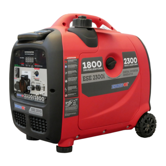
- Page 1 ESE Power Generator TRANSLATION OF THE ORIGINAL OPER- ATING MANUAL ESE 2300 i Article-No. 110 007...
- Page 2 This documentation and parts thereof are subject to copyright. Any use or modi- fication beyond the restrictions of the Copyright Act is forbidden and subject to penalty without the consent of ENDRESS Elektrogerätebau GmbH. This applies in particular to copies, translations, microfilming, as well as storage and processing in electronic systems.
-
Page 3: Table Of Contents
Parallel operation with two ESE 2300 I ........ - Page 4 Storage ..............51 Disposal .
-
Page 5: Directories
Directories Directories List of illustrations Fig. 3-1 Example of a type plate Fig. 3-2 included in delivery Fig. 3-3 Labels on the device Fig. 6-1 Views of the generator Fig. 6-2 Components on the exhaust and operating side Fig. 6-3 Components on the exhaust and maintenance side Fig. -
Page 6: About This Manual
About this manual About this manual We would like to explain to you the safe and correct use of your generator in the best possible way through this operating manual. To do this we have oriented ourselves to the new European standard DIN EN 82079-1 for preparing the user manuals. - Page 7 About this manual Safety symbols These warning notices are usually used in a safety symbol which also emphasis- es the type of danger; see next example. A list of the safety symbols used in this operating manual can be found in Chapter Fig. 3-1 . The safety symbols never stand alone.
-
Page 8: Product Identification
Product identification Product identification Welcome to ENDRESS! We are pleased that you have made the decision to purchase a ENDRESS power generator. You have purchased a high-performance product into which we have embodied decades of our experience and have integrated many functions oriented on daily use. -
Page 9: Foreseeable Misuse
Product identification The generator is not to be connected up to other energy distribution systems (e.g. public power supply) or to other energy generation systems (e.g. other gen- erators, solar plant, etc.). Your generator consists of an inverter alternator which is driven by an internal combustion engine firmly screwed to it. - Page 10 Product identification • Never operate the generator in rooms, narrow pits or vehicles. The combus- tion exhaust gases contain poisonous substances including the odourless but deadly gas carbon monoxide (CO) which, when breathed in, can accu- mulate in cases of poor air circulation to reach deadly concentrations. Also a lack of fresh air circulation leads to overheating and possible damage to the generator right through to destruction.
-
Page 11: Scope Of Delivery Of Your Generator
Scope of delivery of your generator: Fig. 3-2 included in delivery Item Name Battery charging cable Tool set Filling funnel for changing oil Two connecting cables for parallel operation (see 7.7 Parallel op- eration with two ESE 2300 I) -
Page 12: Labels On The Generator
Product identification Labels on the generator An important part of the operating manual is in the form of labelling and notices on your generator. This The label must not be removed and must always be maintained in a legible condition. In a case of damage to the Labels can be or- dered from our customer service team. - Page 13 Product identification Item Label Significance Info Center Warning of hot surfaces Note concerning engine oil Hazard warnings Hazard warning: Never operate in closed spaces Tab. 3-1 Labels on the device...
-
Page 14: For Your Safety
For your safety For your safety The following chapter describes basic Safety instructions for safe operation of your generator. Your device is a very high-performance electrical machine which is potentially dangerous when operated if it has not been installed, commis- sioned, used, serviced and repaired according to the operating manual. - Page 15 For your safety Warning of corrosive substances This warning symbol indicates activities where a risk of chemical burns to the en- vironment as well as people exists, possibly with lethal consequences. Warning of environmentally damaging substances This warning symbol indicates activities where a risk of contaminating the envi- ronment exists, possibly with catastrophic consequences.
-
Page 16: General Safety Instructions
Residual risks As a manufacturer of EU-compliant machines, ENDRESS make great ef- forts to create designs which already eliminate possible risk potentials at the design stage. If this is not possible without significantly impairing the functions of a device, we implement suitable protective measures protect the user from injury. - Page 17 For your safety danger. Exactly impress upon yourself the identification marking of the four different danger levels in order to be able to reliably assess the dan- gers associated with the individual operating states and action steps when reading the operating manual. DANGER! DANGER describes a danger which represents a high level of risk,which can lead to death or severe injuries,when not avoided.
- Page 18 For your safety DANGER! Engine exhaust gases contain poisonous and partially invisible gases such as carbon monoxide (CO) and carbon dioxide (CO2). Risk of death due to poisoning or asphyxiation. ► Ensure that there is good ventilation during the whole period of operation. ►...
- Page 19 For your safety WARNING! Escaping corrosive acid fumes or sulphuric acid during and after the charging process. A risk of suffering severe or even deadly burns. ► Only work with acid-resistant protective equipment. ► Clean surfaces covered in acid immediately using adequate amounts of wa- ter.
- Page 20 For your safety NOTICE! Leaking engine oil and operating fluids can contaminate the soil and groundwater. ► Ensure that the generator is transported horizontally and mounted. ► Make all efforts, at all costs, to prevent escaping of operating fluids. ► Dispose of contaminated soil immediately and according to regulations. NOTICE! Use of wrong or outdated fuel damages or destroys the engine.
-
Page 21: Authorised Operating Personnel - Qualifications And Obligations
For your safety Authorised operating personnel – qualifications and obligations Your Generators is a complex machine, the operation and maintenance of which requires exact knowledge of its functions and danger potentials. Therefore any work with or on the device, of any kind, may only be per- formed by authorised and instructed operating personnel. -
Page 22: Checking The Electrical Safety
Checking the electrical safety Checking the electrical safety Checking of electrical safety requires different measures to be taken which may only be undertaken by respectively authorised personnel. In doing so the respective, pertinent VDE provisions, EN and DIN standards, in their re- spectively valid versions, must be observed. -
Page 23: Description Of The Device
Description of the device Description of the device Views The following section provides an overview of the designation and location of the most important components of your generator. It is important to make oneself familiar with these in order to further understand the de- scribed functions and operating steps and to be able to perform these safe- ly. -
Page 24: Important Components On The Start And Operating Side
Description of the device Important components on the start and operat- ing side Fig. 6-2 Components on the exhaust and operating side Transport wheels Multi-switch Grab handle Cable pull starter Transport grip Transport grip, extendable Control panel Air intake grille... -
Page 25: Important Components Of The Exhaust And Maintenance Side
Description of the device Important components of the exhaust and main- tenance side Fig. 6-3 Components on the exhaust and maintenance side Feet Maintenance flap screw Tank cap with air-release valve Maintenance flap Exhaust gas outlet... -
Page 26: Control Panel Components
Description of the device Control panel components Fig. 6-4 Components on the control panel Schuko socket for 230 V / 16 A / 1~ DC socket for parallel operation and bat- tery operation ECOtronic On / Off Power display Warning lights: - operational indicator Fuel indicator light - overload alarm... -
Page 27: Commissioning
Commissioning Commissioning The following chapter describes the basic procedure for first time or re- peated putting into operation of the generator. Follow the working steps de- scribed below when you put your generator into operation for the first time or restart it again after transporting it. NOTICE! For start-up and operation of a generator on building and assembly sites, Deutsche Gesetzliche Unfallversicherung (DGUV) in DGUV Information... -
Page 28: Refuelling Your Generator
Commissioning NOTICE! Leaking engine oil and operating fluids can contaminate the soil and groundwater. ► Ensure that the generator is transported horizontally and mounted. ► Make all efforts, at all costs, to prevent escaping of operating fluids. ► Dispose of contaminated soil immediately and according to regulations. Roll the generator 1. - Page 29 Commissioning NOTICE! Leaking fuel can contaminate soil and groundwater. ► Take note of the residual quantity in the tank and its maximum filling capacity. ► Always bear in mind that the fuel gauge reacts only after a time delay. ► Fill the tank to a maximum of 95%. ►...
-
Page 30: Starting The Generator
Commissioning Starting the generator Starting the generator for manual operation and with fuel supplied from its own tank is explained here. DANGER! Leaking engine oil and fuel can burn or explode. A risk of suffering severe even deadly burns. ► Prevent engine oil or fuel from leaking out. ►... - Page 31 Commissioning Fig. 7-1 Starting the generator Proceed as follows to start the generator manually directly from the device: Requirements: electrical safety has been checked (see Chapter 5 ). the fuel tank is sufficiently full. oil level is sufficient (fill with engine oil before initial use, see Chapter 8.3.1 and the engine operating and maintenance instructions).
-
Page 32: Turning Off Your Power Generator
Commissioning NOTICE! The automatic low-oil system will not let the engine start if the oil level is too low. ► First refill up to the engine oil level (see Chapter 8.3.1 ), before you restart the engine. ► The automatic low-oil system cannot stop the engine from being damaged due to a low oil level in all cases. -
Page 33: Connection Of Power Consuming Equipment
Commissioning Connection of power consuming equipment DANGER! Mortal danger due to an electric shock if live parts are touched. ► Never operate the device if it is in a damaged condition. ► Never operate the electrical consumers and connecting cable (power con- suming equipment) in a damaged condition. - Page 34 Commissioning...
- Page 35 Commissioning NOTES...
-
Page 36: Parallel Operation With Two Ese 2300 I
Commissioning Parallel operation with two ESE 2300 I Using the parallel connection ability of the ESE 2300 I, you can roughly double the output power through electrical connection of two ESE 2300 I generators. DANGER! Mortal danger due to an electric shock if live parts are touched. -
Page 37: Ecotronic (Idle Down)
Commissioning Connecting up the 1. Place both generators next to each other in such a way that air supply and consumers removal are not impaired. 2. Connect the parallel connecting cable to both generators at the parallel connection sockets 3. Ensure that the parallel connecting cable does get disconnected during par- allel operation. - Page 38 Commissioning Turning off Switch the idle down off as follows: ECOtronic 1. Bring the rocker switch Fig. 6-4 into “0” (OFF) position. Idle down is switched off. The drive motor's speed increases to nominal speed (see Chapter 12 Technical data).
-
Page 39: Charging The Batteries
Commissioning charging the batteries The ESE 2300 I DC connection delivers a DC current of 12 V / 8 A and offers the option to also charge a 12 V lead battery. DANGER! Mortal danger due to an electric shock if live parts are touched. -
Page 40: Maintenance
Contact your dealer or our service hotline at: +49 7123 9737-44 service@endress-stromerzeuger.de NOTICE! Please note that, in the case of a concluded warranty agreement, you will lose all rights to make claims if your generator is not serviced according to manufacturer regulations. -
Page 41: Maintenance Work
Maintenance Maintenance work Maintenance interval according to time or operating hours [h] Item Maintenance step Daily / After 3 After 6 Annual- months / months ly / 300h / 100h Check for cracks and damage; Fuel lines replace if necessary Check the protective conductor connection once every 2 years Maintenance work should be performed by your service partner. -
Page 42: Engine Oil
Maintenance Engine oil The drive motor for your generator, like every internal combustion engine, requires the required engine oil for cooling and inner cooling. It is also im- portant to use the correct oil, both for refilling and changing oil, and to ob- serve the prescribed maintenance intervals. - Page 43 Maintenance CAUTION! The engine and operating equipment on the generator can get very hot while running. Risk of burns ► Never touch any engine parts (in particular the exhaust system) for a few min- utes after ceasing operation. ► Allow the engine to cool off for at least five minutes before changing or check- ing the engine oil.
-
Page 44: Changing The Engine Oil
Maintenance Refilling with en- If the oil level is too low, instigate the next steps to correct the level. gine oil 1. Make ready the engine oil to top up with. 2. Lead the filling funnel also supplied into the previously opened filling opening of the engine (see Fig. -
Page 45: Maintenance Of The Air Filter
Maintenance 4. Ensure that the collection container is placed correctly. 5. Tip the generator slightly in the direction of the collection container to allow draining off of the old oil. The old oil flows through the housing opening into the collection container. 6. -
Page 46: Spark Plug Maintenance
Maintenance 4. Clean the air filter housing and cover, in this case in particular the suction opening. 5. Protect your hands from contact with engine oil. 6. Apply a few drops of new engine oil to the cleaned or new air filter insert. 7. - Page 47 Maintenance Fig. 8-5 Remove spark plug Remove spark plug 1. Unfasten the large screw on the maintenance flap and remove the main- tenance flap 2. Pull the spark plug connector Fig. 8-5 - of the spark plug. To do this always pull directly on the plug, never on the ignition cable! 3.
-
Page 48: Cleaning The Spark Screen
Maintenance Installing the spark 1. Turn the checked spark plug clockwise by hand in the spark plug thread on plug the engine.Fig. 8-5 Ensure that the spark plug is inserted without it tilting, so that the thread is not damaged. 2. -
Page 49: Cleaning The Power Generator
Maintenance 5. Assess the condition of the spark screen and replace it if it is damaged. 6. If the spark screen does not need replacing, clean it thoroughly with the aid of the wire brush. 7. Perform steps 1 to 3 in reverse order in order to fasten the spark screen again. -
Page 50: Storage
Storage Storage It is important to store the device at a suitable storage location as soon as your generator is no longer being used. • The storage location must be roofed and must not be subjected to standing water, aggressive vapours or soiling as well as major accumulation of dust. •... -
Page 51: 10 Disposal
Pure b2b devices (devices which, for appropriate use, or exclusively are only used the commercial area) must not be disposed of over public collecting points in Germany and further EU countries. Speak to your authorised ENDRESS gen- erator dealer about handing back your recycling waste electrical equipment. The dealer is also your point of contact for any differing regulations on the respective country of deployment. -
Page 52: 11 Troubleshooting
Troubleshooting 11 Troubleshooting The following table is an aid for you to use in a case where faults arise during use. Based on experience a number of malfunctions can already be removed by operating personnel or the possible causes limited. In all other cases contact your service partner as described in the table. - Page 53 Troubleshooting Malfunction possible cause Correction Fuel level too low Top up with fuel The fuel filter is clogged. Replace the fuel filter. Engine oil level too low (oil lack auto- Bring the engine oil level up to The engine starts but stops matic switch-off) the maximum again shortly afterwards...
- Page 54 Troubleshooting Please contact our customer service for further fault diagnosis as well as pro- curement of original spare parts and wear parts at Tel. +49-(0)-7123-9737-44 service@endress-stromerzeuger.de or www.endressparts.com (see Chapter 13 )
-
Page 55: 12 Technical Data
Technical data 12 Technical data The following table contains the technical data for your generator. Name Value Unit ESE 2300 i Type of alternator Inverter Maximum output [[LTP] 2300 Continuous output [PRP] 1800 Nominal frequency [Hz] Nominal speed 3600 - 5300... -
Page 56: 13 Replacement Parts
Replacement parts 13 Replacement parts Maintenance and replacement parts can be obtained quickly and easily from your responsible ENDRESS service partner or ENDRESS dealer. You can alternatively obtain support from our central customer service by telephone: +49 (0) 71239737-44 by email: service@endress-stromerzeuger.de Have the item and serial number of your device ready for identification. - Page 57 Replacement parts NOTES...
- Page 58 Replacement parts NOTES...
-
Page 59: Keyword Index
Replacement parts Keyword index DIN EN ISO 12100 16 DIN EN ISO 8528-13 16 automatic low-oil system 33 DIN VDE 82079-1 6 ISO 3864 16 Battery charging cable 11 ISO 7010 14 standards DIN EN 60204 16 Cable pull starter 25 Suction side 24 Control panel 25 Control side 24... - Page 60 Elektrogerätebau GmbH Neckartenzlinger Str. 39 D-72658 Bempflingen, Germany Tel: +49 (0) 7123 /9737-0 Fax: +49 (0) 7123 /9737-50 Email: info@endress-stromerzeuger.de www: www.endress-stromerzeuger.de © 2019, ENDRESS Elektrogerätebau GmbH...
Need help?
Do you have a question about the ESE and is the answer not in the manual?
Questions and answers