
Related Manuals for Endress ESE 607 DBG ES DIN


Summary of Contents for Endress ESE 607 DBG ES DIN
- Page 1 OPERATING MANUAL ESE 607 DBG DIN Article-No. 151202 / 156202 ESE 607 DBG ES DIN Article-No. 151212 / 156212 ESE 957 DBG ES DIN Article-No. 151214 / 156214...
- Page 2 E134021 Publication date February 2013 Copyright © 2013, ENDRESS Elektrogerätebau GmbH This documentation and parts thereof are subject to copyright. Any use or modifi cation beyond the restrictions of the Copyright Act is forbidden and subject to penalty without the consent of ENDRESS Elektrogerätebau GmbH.
-
Page 3: Table Of Contents
Table of Contents General information about this manual ............7 Documentation and accessories ................8 General safety regulations ................11 Safety warning symbols ..................9 Important safety warning ..................11 Intended use ......................12 Operating personnel - Qualifi cations and Obligations ........... 17 2.2.1 Foreseeable incorrect use or inappropriate handling .......... - Page 4 Table of Contents Starting the generator .................... 37 Switching the generator off ..................41 Connecting up to consumers ................. 42 Checking the protective conductor ................ 43 Monitoring the operating status using the multifunction display ......44 Laying up the generator ..................48 Using special fi...
- Page 5 Table of Contents Troubleshooting ....................71 Technical Specifi cations ..................75 List of illustrations Figure 2-1: Signs on the generator ..........19 Figure 3-1: Views of the generator ..........27 Figure 3-2: Components on the operating and engine side ..28 Figure 3-3: Components on the exhaust and generator side ..29 Figure 3-4: Control panel components ........30 Figure 3-5: Standard accessories components ......31 Figure 3-6: Components of the special accessories....31...
-
Page 6: Table Of Contents
Table of Contents List of charts Table 2.1: Danger zones and work areas on the generator ..18 Table 2.2: Signs on the generator..........21 Table 4.1: Protective conductor test lamp........43 Table 5.1: FI protection switch test ..........51 Table 5.2: Insulation monitoring without switching off ....52 Table 5.3: Insulation monitoring whilst running without switching off ................53 Table 5.4: 3-way fuel valve switch positions .......60... -
Page 7: General Information About This Manual
General information about this manual General information about this manual These operating instructions must be read carefully and understood before using the generator. These operating instructions are intended to familiarise you with the basic operation of the generator. These operating instructions contain important information on using the generator safely and appropriately. -
Page 8: Documentation And Accessories
Documentation and accessories General information about this manual Documentation and accessories In addition to these operating instructions, the following documents are relevant for the generator: ● operating instructions and maintenance instructions for the engine (Briggs & Stratton Corporation) ● Briggs & Stratton Service Germany (Briggs & Stratton Corporation) ●... -
Page 9: Safety Warning Symbols
Safety warning symbols General information about this manual Safety warning symbols The safety warning symbol indicates that a source of danger exists. The safety warning symbols used in the work area of the machine/plant and the entire technical documentation correspond to the Council Directive 92/58/EEC - Minimum requirements for the provision of safety and/or health signs at work. - Page 10 General information about this manual Safety warning symbols Notes ESE 607 / 957 DBG (ES) DIN Issued: February 2013...
-
Page 11: General Safety Regulations
Whoever operates the generator or works with it must read this chapter and comply with its regulations in practice. ENDRESS generators are designed to operate electrical equipment with appropriate power output requirements. Other applications can lead to injury to the operating personnel and to damage to the generator as well as other damage to equipment. -
Page 12: Intended Use
General safety regulations Intended use WARNING! The following actions are not permitted. ● operation in explosion-prone environments ● operation in fi re-prone environments ● operation in confi ned areas ● operation from a vehicle platform that has not been swung ●... -
Page 13: Foreseeable Incorrect Use Or Inappropriate Handling
General safety regulations Intended use The generator is not to be connected up to other energy distribution systems (e.g. public power supply) or to other energy generation systems (e.g. other generators). The generator is not to be used in explosion-prone environments. The generator is not to be used in fi... -
Page 14: Residual Risks
2.2.2 Residual risks General safety regulations Intended use The residual risks were analysed and evaluated before beginning the design and planning of the generator using a risk analysis tool. Residual risks which cannot be avoided by implementing design measures during the whole life cycle of the generator can be: ●... - Page 15 General safety regulations Intended use Mortal danger Mortal danger to persons from the generator can arise from: ● incorrect use ● inappropriate handling ● missing protective devices ● defective or damaged electrical components ● fuel vapours ● engine exhaust gases ●...
- Page 16 General safety regulations Intended use Generator‘s performance or The generator‘s performance or functionality can be limited by: functionality - Limitations ● inappropriate handling ● inappropriate maintenance or repair work ● unsuitable operating fl uids ● an installation altitude greater than 100 metres above sea level ●...
-
Page 17: Operating Personnel - Qualifi Cations And Obligations
Operating personnel - Qualifi cations and Obligations General safety regulations Operating personnel - Qualifi cations and Obligations Only appropriately authorised personnel may work with or on the generator. The authorised operating personnel must: ● be of age. ● be trained in First Aid and be able to provide it. ●... -
Page 18: Danger Zones And Work Areas
Danger zones and work areas General safety regulations Danger zones and work areas The danger zones and work areas on the generator are determined by the activities to be performed within the individual life cycles: Life cycle Activity Danger zone Work area Transport in the vehicle... -
Page 19: Signs On The Generator
Signs on the generator General safety regulations Signs on the generator These signs must be fi tted on the generator and be kept in a clearly legible condition: Reference note - three-way valve EMERGENCY-STOP Nameplate Fuel note Reference note - noise emission Reference note - Engine maintenance Figure 2-1: Signs on the generator Reference note - read operating... - Page 20 General safety regulations Signs on the generator Sign Name External refuelling Nameplate Reference note - noise emission Reference note - read operating instructions Cable extension Short operating instructions Reference note - EMERGENCY-STOP ESE 607 / 957 DBG (ES) DIN Issued: February 2013...
-
Page 21: Table 2.2: Signs On The Generator
General safety regulations Signs on the generator Sign Name Fuel note Reference note - maintenance intervals Reference note - no naked fl ames Potential equalization (earthing for FI) Note on the hot surface Table 2.2: Signs on the generator ESE 607 / 957 DBG (ES) DIN Issued: February 2013... -
Page 22: General Safety Warnings
General safety warnings General safety regulations General safety warnings The generator‘s construction is not to be modifi ed in any way. The engine‘s nominal rpm has been set in the factory and is not to be changed. All protective covers must be at hand and functional. All signs on the generator must be in place and be in a clearly legible condition. - Page 23 General safety regulations General safety warnings Naked fl ames and non-safety lights are prohibited in the generator‘s danger zone. Consumption of alcohol, drugs, medications, or other mind- altering substances is prohibited. The authorised personnel must be familiar with the alternator components and their function and know how to use them.
- Page 24 General safety regulations General safety warnings Generating electricity The electrical safety must be checked before each start-up. Do not cover the equipment during use. Do not obstruct or block the air supply. Do not use starting aids. Devices must not be connected during start-up. Only tested and authorised cables may be used for the power network.
- Page 25 General safety regulations General safety warnings Maintenance and repair work Operating personnel may only carry out the maintenance or repair work described in these operating instructions. All other maintenance or repair tasks may only be carried out by specially trained and authorised specialists. Always remove the ignition key and the spark plug sockets before beginning maintenance and/or repair work.
- Page 26 Notes ESE 607 / 957 DBG (ES) DIN Issued: February 2013...
-
Page 27: Power Generator Ese 607 / 957 Dbg (Es) Din Description
Power generator ESE 607 / 957 DBG (ES) DIN description Power generator ESE 607 / 957 DBG (ES) DIN description Views of the generator Views of the generator The components and functionality of the generator are described in this section. The generator components are distributed on all four sides. -
Page 28: Operating And Engine Side Components
3.1.1 Operating and engine side components Power generator ESE 607 / 957 DBG (ES) DIN description Views of the generator Carrying handle Side fl ap Storage compartment for operating Engine spark plug instructions / standard accessories Filler neck Hinged window circuit breaker Figure 3-2: Components on the operating and engine side Mounting holes according to DIN 14685 Upper fl... -
Page 29: Exhaust And Generator Side Components
3.1.2 Exhaust and generator side components Power generator ESE 607 / 957 DBG (ES) DIN description Views of the generator Air fi lter cover Exhaust Oil fi ller neck Oil dipstick Recoil starter Spark plug connector Figure 3-3: Components on the exhaust and generator side Carrying handle Storage compartment Upper fl... -
Page 30: Control Panel Components
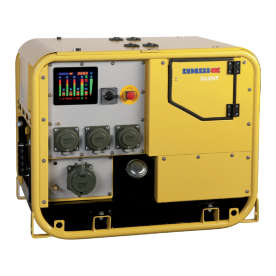
3.1.3 Control panel components Power generator ESE 607 / 957 DBG (ES) DIN description Views of the generator Circuit breaker / hinged window (under Speed reduction switch (optional) the upper fl ap) Insulation monitor (optional) Socket for protective earthing conductor 230V / ~ Schuko socket test Figure 3-4: Control panel components... -
Page 31: Accessory Components
3.1.4 Accessory components Power generator ESE 607 / 957 DBG (ES) DIN description Views of the generator 3.1.4.1 Standard accessories Spark plug socket Test cable User information (operating instructions Test tip for the engine, as well as these operating Spark plugs (2×) instructions) Figure 3-5: Standard accessories components 3.1.4.2 Special accessories... -
Page 32: Function And Operating Mode
Function and operating mode Power generator ESE 607 / 957 DBG (ES) DIN description Function and operating mode The synchronous alternator is fi rmly coupled to the drive engine. The assembly is installed in a stable frame and equipped with a fl... - Page 33 Power generator ESE 607 / 957 DBG (ES) DIN description Function and operating mode Notes ESE 607 / 957 DBG (ES) DIN Issued: February 2013...
-
Page 34: Operating The Ese 607 / 957 Dbg (Es) Din
Operating the ESE 607 / 957 DBG (ES) DIN Transporting the generator Operating the ESE 607 / 957 DBG (ES) DIN Transporting the generator The operation of the generator is described in this section. Proceed as follows to transport the generator. Requirements The following requirements must be fulfi... -
Page 35: Setting Up The Generator
Setting up the generator Operating the ESE 607 / 957 DBG (ES) DIN Setting up the generator Proceed as follows to set up the generator. Requirements The following requirements must be fulfi lled: ● an even and fi rm substratum outdoors ●... -
Page 36: Refuelling The Generator
Refuelling the generator Operating the ESE 607 / 957 DBG (ES) DIN Refuelling the generator Proceed as follows to refuel the generator. Requirements The following requirements must be fulfi lled: ● switched off generator (see 4.5) ● a cooled down generator ●... -
Page 37: Starting The Generator
Starting the generator Operating the ESE 607 / 957 DBG (ES) DIN Starting the generator Requirements The following requirements must be fulfi lled: ● checked electrical reliability (see 6.3) ● fi lled fuel tank (see 4.3) ● a possibly connected fuelling device (special accessory) ●... -
Page 38: Figure 4-1: Pull On Manually-Operated Choke
Operating the ESE 607 / 957 DBG (ES) DIN Starting the generator Starting the engine Start the engine as follows: Figure 4-1: Pull on manually-operated choke ELECTRICAL START 1. Open on fl ap side (see Figure 4-1-(2)). 2. Pull on the choke (Figure 4-1-(2)) (completely for a cold engine / appropriately less for a warm engine) and hold fi... - Page 39 Operating the ESE 607 / 957 DBG (ES) DIN Starting the generator REFERENCE NOTE Only activate the starter briefl y (max. 5 - 10 seconds). Never start or run the engine with the battery disconnected. 4. Move the choke (Figure 4-1-(1)) back into its start position. ...
- Page 40 Operating the ESE 607 / 957 DBG (ES) DIN Starting the generator REFERENCE NOTE Place your foot on the unit‘s frame to support yourself and make it easier to pull the starter. The engine starts. 5. Release the choke. ...
-
Page 41: Switching The Generator Off
Switching the generator off Operating the ESE 607 / 957 DBG (ES) DIN Switching the generator off Proceed as follows to shut down the generator. WARNING! Hot parts can ignite fl ammable and explosive materials. ● avoid fl ammable materials at the work location. ●... -
Page 42: Connecting Up To Consumers
Connecting up to consumers Operating the ESE 607 / 957 DBG (ES) DIN Connecting up to consumers Proceed as follows to connect up consumers to the generator. Requirements The following requirements must be fulfi lled: ● started generator (see 4.4) ●... -
Page 43: Checking The Protective Conductor
Checking the protective conductor Operating the ESE 607 / 957 DBG (ES) DIN Checking the protective conductor Proceed as follows to check the protective conductor connection between the generator and the consumer. Requirements The following requirements must be fulfi lled: ●... -
Page 44: Monitoring The Operating Status Using The Multifunction Display
Monitoring the operating status using the multifunction display Operating the ESE 607 / 957 DBG (ES) DIN Monitoring the operating status using the multifunction display All LEDs light up for about 2 seconds to allow checking as soon as the START-STOP switch is set to the position „Operate“. The normal operational lighting is then shown afterwards for about 30 seconds. - Page 45 Operating the ESE 607 / 957 DBG (ES) DIN Monitoring the operating status using the multifunction display Oil pressure: If the display (see Fig. 4-55-(15)) lights up red whilst the generator is running then the oil pressure is too low and the generator will switch off automatically or the buzzer will sound and this can be acknowledged using the acknowledgement button.
- Page 46 Operating the ESE 607 / 957 DBG (ES) DIN Monitoring the operating status using the multifunction display Fuel tank fi lling level: The display (see Figure 4-5-(6)) gives a rough indication of the contents of tank. Symbol Display Signifi cance green Fill level 100% green...
- Page 47 Operating the ESE 607 / 957 DBG (ES) DIN Monitoring the operating status using the multifunction display EMERGENCY-STOP button: If the “OFF” symbol glows red (see Fig. 4-55-(4)) and the buzzer sounds, the EMERGENCY STOP button has been pressed. The buzzer can be acknowledged using the acknowledgement button.
-
Page 48: Laying Up The Generator
Observe all local laws and regulations concerning correct disposal of such parts and substances. Your authorised ENDRESS generator dealer is happy to advise you. Please observe the pertinent environmental protection regulations when disposing of the old oil. - Page 49 Operating the ESE 607 / 957 DBG (ES) DIN Disposal Notes ESE 607 / 957 DBG (ES) DIN Issued: February 2013...
-
Page 50: Using Special Fi Ttings / Accessories
Using special fi ttings / accessories FI protection switch Using special fi ttings / accessories FI protection switch The FI protection switch option can only be supplied by the factory. The FI protection switch (RCD) is a protective measure against dangerous body currents according to DIN VDE 0100-551. -
Page 51: Figure 5-1: Fi Protection Switch
Using special fi ttings / accessories FI protection switch Checking the FI protection 1. The generator must have been started (see 4.4). switch: 2. Move the protection switch (see Figure 5-1-(20)) into Pos. 1. 3. Activate the test switch (see Figure 5-1-(10)). ... -
Page 52: Insulation Monitoring Using E-Mcs 4.0 (Without Switching Off)
Insulation monitoring using E-MCS 4.0 (without switching off) Using special fi ttings / accessories Insulation monitoring using E-MCS 4.0 (without switching off) The insulation monitoring option can only be supplied by the factory. Requirements The following requirements must be fulfi lled: ●... -
Page 53: Maxdrive
Using special fi ttings / accessories Maxdrive Insulation monitoring whilst 1. Plug in the device and switch on. running: The switch position displays the result (see Figure 4-5-(9)): Symbol Signifi cance Buzzer sounds if lit in yellow Insulation fault (≤ 23kΩ) stays off Connected unit is OK ... -
Page 54: Speed Reduction At Idle
Speed reduction at idle Using special fi ttings / accessories Speed reduction at idle Proceed as follows to operate the generator using idle speed reduction. Requirements The following requirements must be fulfi lled: ● a ready for operation generator ● a started generator (see 4.4) Switching on idle speed reduction Switch on idle speed reduction as follows:... -
Page 55: Remote Start Device
Remote start device Using special fi ttings / accessories Remote start device Proceed as follows to operate the generator using the remote start device. Requirements The following requirements must be fulfi lled: ● an operational generator WARNING! Devices with a remote start device are fi tted with an automatic choke. -
Page 56: Figure 5-5: Remote Start Device With Can Plug
Using special fi ttings / accessories Remote start device Disconnecting the remote Disconnect the remote start device as follows: start device 1. Release the clip and then pull the remote start operating status / generator connecting cable plug out. 2. Fold down the protective cap (if fi tted) onto the remote start socket and lock in place using the clip. -
Page 57: External Start Device
External start device Using special fi ttings / accessories External start device Proceed as follows to operate the generator using the external start device. Requirements The following requirements must be fulfi lled: ● an operational generator Connecting up the external start device Connect up the external start device as follows: 1. -
Page 58: Battery Charge Retention Device
Battery charge retention device Using special fi ttings / accessories Battery charge retention device Proceed as follows to charge the starter battery for the generator over the battery charge retention device. Requirements The following requirements must be fulfi lled: ● an operational generator Connecting up the battery Connect up the battery charge retention device (charge charge retention device... -
Page 59: Figure 5-9: Connecting Up The Battery Charge Retention Device
Using special fi ttings / accessories Battery charge retention device 1. Unscrew cover (Figure 5-7-(2)) of the start socket (Figure 5-7-(1)) for the starter battery charge retention device. 2. Insert plug for the external energy source (e.g. a battery charging device) / charge retention device socket connecting cable and lock in place by turning to the right. -
Page 60: 3-Way Fuel Valve / Refuelling Device
3-way fuel valve / Refuelling device Using special fi ttings / accessories 3-way fuel valve / Refuelling device Proceed as follows to use the refuelling device with the generator. Requirements The following requirements must be fulfi lled: ● a ready for operation generator ●... - Page 61 Using special fi ttings / accessories 3-way fuel valve / Refuelling device WARNING! Leaking engine oil and petrol can contaminate the soil and groundwater. ● do not fi ll the canister completely. ● allow the fuelling device to drain off. WARNING! Using the wrong fuel will destroy the engine.
- Page 62 Using special fi ttings / accessories 3-way fuel valve / Refuelling device Connecting up the canister Connect the cannister up to the fuelling device as follows: 1. Open sealing cap on the canister. 2. Introduce hose. 3. Engage catch on the fuelling device. ...
-
Page 63: Exhaust Hose
Exhaust hose Using special fi ttings / accessories Exhaust hose Proceed as follows to use the exhaust hose with the generator. Requirements The following requirements must be fulfi lled: ● a ready for operation generator WARNING! Exhaust gases can cause fatal asphyxiation. ●... -
Page 64: Generator Ese 607 / 957 Dbg (Es) Din Maintenance
Generator ESE 607 / 957 DBG (ES) DIN maintenance Generator ESE 607 / 957 DBG (ES) DIN maintenance Maintenance plan Maintenance plan Generator maintenance is described in this section. Only personnel from the manufacturer may carry out maintenance or repair work not described in this section. The maintenance work specifi... -
Page 65: Maintenance Work
Maintenance work Generator ESE 607 / 957 DBG (ES) DIN maintenance Maintenance work Only authorised personnel are allowed to carry out maintenance tasks. Carry out all maintenance tasks specifi ed in the maintenance plan according to the specifi cations in the enclosed operating 6.2.1 Engine oil and maintenance instructions for the engine (Figure 3-5-(2)). -
Page 66: Figure 6-2: Changing The Oil
Generator ESE 607 / 957 DBG (ES) DIN maintenance Maintenance work Checking the oil level Check the oil level as follows: 1. Pull out the dipstick (Figure 6-1-(2)) and use a clean cloth to wipe it. 2. Reinsert the dipstick and take it out again. Drain off some of the oil if the level is above the upper mark and refi... - Page 67 Generator ESE 607 / 957 DBG (ES) DIN maintenance Maintenance work Changing the oil 1. Disassemble the side plate on the operating side of the generator. 2. Attach oil drain channel (Figure 6-2-(3)) as shown. 3. Remove oil drain screw (Figure 6-2-(2)) so that engine oil runs off completely.
-
Page 68: Changing The Starter Battery
● avoid sparks when handling cables and electrical devices, as well as electrostatic discharge. ● avoid short-circuits. WARNING! The Endress battery is maintenance-free throughout its entire service life. ● never open the battery — this may destroy it. ESE 607 / 957 DBG (ES) DIN... -
Page 69: Replacing Fuses
6.2.3 Replacing fuses Generator ESE 607 / 957 DBG (ES) DIN maintenance Maintenance work Replacing fuses (only for the special accessory external start socket, socket, charging retention and/or remote start device) 1. Open the fuse holder. 2. Replace the fuse. 3. -
Page 70: Checking The Electrical Safety
Checking the electrical safety Generator ESE 607 / 957 DBG (ES) DIN maintenance Checking the electrical safety Only appropriately authorised personnel may check the electrical safety. The electrical reliability must be checked in accordance with the applicable VDE regulations, EN and DIN standards and especially the current version of the BGV A3 accident prevention regulations. -
Page 71: Troubleshooting
Troubleshooting Troubleshooting Checking the electrical safety This section describes problems that authorised personnel can eliminate during operation. Each occurring problem is described with its possible cause and the respective corrective measure. The authorised personnel must immediately shut down the generator and inform the responsible and authorised service personnel if a problem cannot be solved with the aid of the following table. - Page 72 Troubleshooting Checking the electrical safety Malfunction Possible cause Correction Starter battery has no power. Battery is discharged. Charge battery. Battery is defective. Exchange battery. Battery terminals are oxidized. Clean battery terminals and if necessary apply terminal grease. Starter battery is not being Alternator / charge regulator Call service staff.
-
Page 73: Table 7.1: Problems During Generator Operation
Troubleshooting Checking the electrical safety Malfunction Possible cause Correction Faults on the special equipment The engine does not start in The remote start equipment Insert the remote start remote start mode. connecting plug is not inserted equipment connecting plug properly. correctly. - Page 74 Troubleshooting Checking the electrical safety Notes ESE 607 / 957 DBG (ES) DIN Issued: February 2013...
-
Page 75: Technical Specifi Cations
Technical Specifi cations Technical Specifi cations Checking the electrical safety The technical specifi cations are described in this section. Describes the operation of the generator. Figure 8-1: Generator dimensions ESE 607 / 957 DBG (ES) DIN Issued: February 2013... -
Page 76: Table 8.1: Generator Technical Data
Technical Specifi cations Checking the electrical safety Technical specifi cations Name Value Unit ESE 607 ESE 957 Type DBG (ES) DBG ES Nominal output [kVA] Nominal output factor [cos ] Nominal frequency [Hz] Nominal speed 3000 3000 [min Nominal voltage 3~ Nominal voltage 1~ Rated current 3~ 12.9... - Page 77 Technical Specifi cations Checking the electrical safety Ambient conditions Name Value Unit Setting up height above sea level < 100 Temperature < 25 [°C] Relative air humidity < 30 Reduced power for each Power reduction Unit additional [°C] Table 8.2: Ambient conditions for the generator Distribution network max.
- Page 78 Technical Specifi cations Checking the electrical safety Notes ESE 607 / 957 DBG (ES) DIN Issued: February 2013...
- Page 79 ESE 607 / 957 DBG (ES) DIN Issued: February 2013...
Need help?
Do you have a question about the ESE 607 DBG ES DIN and is the answer not in the manual?
Questions and answers