
Subscribe to Our Youtube Channel
Related Manuals for Endress ESE 1006 SG-GT ES DUPLEX


Summary of Contents for Endress ESE 1006 SG-GT ES DUPLEX
- Page 1 OPERATING INSTRUCTIONS ESE 1006 SG-GT ES DUPLEX ARTICLE NO: 113160 ESE 1006 SG-GT ES DUPLEX ARTICLE NO: 113161 ESE 1306 SG-GT ES DUPLEX ARTICLE NO: 113158 ESE 1506 SG-GT ES DUPLEX ARTICLE NO: 113159 SEA13 ARTICLE NO: 151647...
- Page 2 E133621 Publication date January 2013 Copyright © 2013, ENDRESS Elektrogerätebau GmbH This documentation and parts thereof are subject to copy- right. Any use or modification beyond the restrictions of the Copyright Act is forbidden and subject to penalty without the consent of ENDRESS Elektrogerätebau GmbH.
-
Page 3: Table Of Contents
Table of Contents General information ..................7 Documents and accessories ................8 Safety symbols ....................9 General Safety Regulations ................11 Important safety warning .................. 11 2.1.1 Intended use ....................12 2.1.2 Foreseeable incorrect use or inappropriate handling ........13 2.1.3 Residual risks .................... - Page 4 Table of Contents Refuelling the generator ................... 32 Starting the generator ..................34 Switching the generator off ................36 Connect up to consumers ................37 ECOtronic (idle down) ..................38 Monitoring the operating status via the “ECD 06 control display” ..... 39 Putting the generator out of service..............
- Page 5 Table of Contents Replacement parts ..................67 Protective cover / Engine / generator ............... 67 Electrical compartment..................69 Warranty / Maintenance .................. 71 Table of Contents List of illustrations Fig. 21: Signs on the generator .......18 Fig. 31: Views of the generator .......25 Fig.
- Page 6 Table of Contents List of tables Table 2.1: Danger zones and work areas on the generator 17 Table 2.2: Signs on the generator........19 Table 5.1: FI protection switch test ........44 Table 5.2: Insulation monitoring plus switching off ....45 Table 5.3: Insulation monitoring whilst running without switching off ..............46 Table 6.1: Generator maintenance plan......52 Table 7.1: Problems arising during generator operation ..61...
-
Page 7: General Information
 General information 1 General information These operating instructions must be read carefully and un- derstood before using the generator. These operating instructions are intended to familiarise you with the basic operation of the generator. These operating instructions contain important information on using the generator safely and appropriately. -
Page 8: Documents And Accessories
General information  1.1 Documents and accessories In addition to these operating instructions, the following doc- uments are relevant for the generator: Operating manual and maintenance instructions for the engine (Subaru) Regulations for handling the battery Circuit diagram for the generator The operating manual and the maintenance instructions from the engine manufacturer are integral components of these instructions and must be observed. -
Page 9: Safety Symbols
 General information 1.2 Safety symbols The safety warning symbol indicates that a source of danger exists. The safety warning symbols used in the work area of the machine/plant and the entire technical documentation correspond to the Council Directive 92/58/EEC - Minimum requirements for the provision of safety and/or health signs at work. - Page 10 General information  Notes ESE 1006 / 1306 / 1506 (D)SG-GT ES Duplex Stand: January 2013...
-
Page 11: General Safety Regulations
Whoever operates the generator or works with it must read this chapter and comply with its regulations in practice. 2.1 Important safety warning ENDRESS generators are designed to operate electrical equipment with appropriate power output requirements. Oth- er applications can lead to injury to the operating personnel and to damage to the generator as well as other damage to equipment. -
Page 12: Intended Use
 The following actions are not permitted. Operation in explosion-prone environments Operation in fire-prone environments Operation in confined areas Operation from a vehicle platform that has not been swung out Operation without the necessary safety redundancies ... -
Page 13: Foreseeable Incorrect Use Or Inappropriate Handling
& The generator is not to be connected up to other energy dis- tribution systems (e.g. public power supply) or to other ener- gy generation systems (e.g. other generators). The generator is not to be used in explosion-prone environ- ments. The generator is not to be used in fire-prone environments. -
Page 14: Residual Risks
 Unintended use 2.1.3 Residual risks Before commencing design and planning, the residual risks of the generator ESE 1006 / 1306 / 1506 (D)SG-GT ES Du- plex were analysed and evaluated by means of a hazard analysis according to EN 1050. Constructionally unavoidable residual risks during the entire service life of the ESE 1006 / 1306 / 1506 (D)SG GT (ES) Duplex generators can be:... - Page 15 & Transport Hot components Recoiling starter rope on the engine Environmental hazards Environmental hazards involving the generator may be caused by: Inappropriate handling Operating fluids (fuel, lubricants, engine oil, etc.) Exhaust gas emission Noise emission ...
-
Page 16: Operating Personnel - Qualifications And Obligations
 2.2 Operating personnel – Qualifications and obligations Only appropriately authorised personnel may work with or on the generator. The authorised operating personnel must: be at least 18 years old. be trained in first aid and able to provide it. ... -
Page 17: Danger Zones And Work Areas
& 2.4 Danger zones and work areas The danger zones and work places (work areas) around the generator are determined by the activities to be undertaken within the individual life cycles: Life cycle Activity Danger zone Work area Transport in the vehicle Radius of 1.0 m none by the operating person-... -
Page 18: Signs On The Generator
 2.5 Signs on the generator These signs must be fitted on the generator and be kept in a clearly legible condition: Fig. 21: Signs on the generator Nameplate Reference note - Petrol Reference note - Hot surface Reference note - no naked flames Reference note - noise emission Potential equalization (earthing for FI) Reference note - read operating instruc-... -
Page 19: Table 2.2: Signs On The Generator
& Sign Name Nameplate Hot surface warning Reference note - noise emission Reference note - read operating instructions Reference note - Petrol Reference note - no na- ked flames Potential equalization (earthing for FI) Table 2.2: Signs on the generator ESE 1006 / 1306 / 1506 (D)SG-GT ES Duplex Status at: January 2013... -
Page 20: General Safety Instructions
 2.6 General safety instructions The generator's construction may not be modified in any way. The motor's nominal rpm has been set in the factory and may not be changed. All protective covers must be at hand and functional. All signs on the generator must be in place and be in a clear- ly legible condition. - Page 21 & Open flames and light are prohibited in the generator's dan- ger zone. Consuming alcohol, drugs, medicines, or other conscious- ness-expanding and/or changing substances is prohibited. The authorised personnel must be familiar with the generator components and their function and know how to use them. Transport The generator is only be transported after it has cooled down.
- Page 22  Do not operate the generator without a sound damper. It is prohibited to operate the generator without air filters and with an opened air filter cover. Refuelling It is prohibited to refill the generator's fuel tank during opera- tion. It is prohibited to refill the fuel tank on the generator when it is still hot.
- Page 23 & Maintenance and repair Operating personnel may only carry out the maintenance or work repair work described in these operating instructions. All other maintenance or repair tasks may only be carried out by specially trained and authorised specialists. Always remove the ignition key and the spark plug sockets before beginning maintenance and/or repair work.
- Page 24  ESE 1006 / 1306 / 1506 (D)SG-GT ES Duplex Stand: January 2013...
-
Page 25: The Generator Ese 1006 / 1306 / 1506 (D)Sg-Gt Es Duplex
& 3 The generator ESE 1006 / 1306 / 1506 (D)SG-GT ES Duplex The components and functionality of the generator are de- scribed in this section. 3.1 Generator components The generator components are distributed on all four sides. Fig. 31: Views of the generator Engine side Generator side Control side... -
Page 26: Generator And Control Side Components
3.2 Generator and control side components Fig. 32: Components of the operating and generator side Front panel Tank filling opening Transportation Fill level indicator of tank Ventilation openings (keep free and unob- Carrying handle structed) ESE 1006 / 1306 / 1506 (D)SG-GT ES Duplex Stand: January 2013... -
Page 27: Exhaust And Engine Side Components
& 3.3 Exhaust and engine side components Fig. 33: Exhaust and engine side components Alternator Oil filter Battery Oil drain screw Silencer outlet Potential equalisation screw (for an op- tional FI earthing connection) Spark plug connector ESE 1006 / 1306 / 1506 (D)SG-GT ES Duplex Status at: January 2013... -
Page 28: Control Panel Components
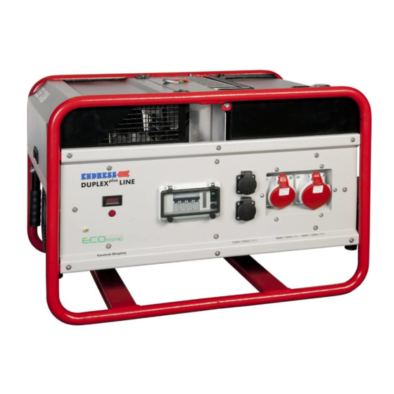
3.4 Control panel components Fig. 34: Control panel components Multi-functional display Circuit breaker (under hinged window) Switch for EcoTronic (under hinged window) Schuko (shockproof) power sockets CEE sockets (vary with the models, see spare parts list at the end of these operating instructions. CEE sockets (vary with the models, see spare parts list at the end of these operating instructions. -
Page 29: Function And Mode Of Operation
& 3.5 Function and mode of operation The synchronous generator is firmly coupled to the drive engine. The aggregate is installed in a stable frame with a cover hood and equipped with flexible and low vibration sus- pension elements. Splash-proof earthed power and CEE sockets with a nominal voltage of 230 and/or 400 V/50 Hz supply the power. - Page 30 ESE 1006 / 1306 / 1506 (D)SG-GT ES Duplex Stand: January 2013...
-
Page 31: Operation
& 4 Operation The operation of the generator is described in this section. 4.1 Transporting the generator Proceed as follows to transport the generator. Requirements The following requirements must be met: The generator must be turned off The generator must have cooled down. ... -
Page 32: Setting Up The Generator
 4.2 Setting up the generator Proceed as follows to set up the generator. Requirements The following requirements must be met: An even and firm substratum outdoors There are no inflammable materials at the operating site There are no explosive materials at the operating site WARNING! Leaking engine oil and petrol can contaminate the soil and groundwater. - Page 33 & WARNING! Leaking engine oil can contaminate the soil and groundwater. Do not fill the tank completely. Use a filling aid. WARNING! Using the wrong fuel will destroy the engine. Only refuel with lead-free regular grade petrol RON 91. Refuelling the device Refuel the generator as follows: 1.
-
Page 34: Starting The Generator
 4.4 Starting the generator Proceed as follows to start the generator. Requirements The following requirements must be met: Electrical safety check (see 6.3) Fuel tank has been filled (see 4.3) sufficient oil level (fill with engine oil before initial use, see the engine operating and maintenance instructions) ... -
Page 35: Fig. 4 1: Starting The Motor
& Fig. 41: Starting the motor to the “START” Electrical start 1. Turn the start / stop switch 1 (Fig. 4 position on the right 1 (see Fig. 4 -(3)) NOTE Only activate the starter briefly (max. 5-10 seconds). Never start or run the engine with the battery disconnected. -
Page 36: Switching The Generator Off
 4.5 Switching the generator off Proceed as follows to shut down the generator. WARNING! Hot parts can ignite flammable and explosive materials. Avoid flammable materials at the operating site. Avoid explosive materials at the operating site. Allow the generator to cool down. -
Page 37: Connect Up To Consumers
& 4.6 Connect up to consumers Proceed as follows to connect appliances to the generator. Requirements The following requirements must be met: generator has been started (see 4.4) device switched off WARNING! Electric shocks cause injury or death. ... -
Page 38: Ecotronic (Idle Down)
 4.7 ECOtronic (idle down) Proceed as follows to operate the generator with idling speed reduction. Requirements The following requirements must be met: generator is ready for operation generator has been started (see 4.4) Fuse is OK 3 (Fig. -
Page 39: Monitoring The Operating Status Via The "Ecd 06 Control Display
& 4.8 Monitoring the operating status via the “ECD 06 control display” The display 4 is always active when the (see Fig. 4 -(1)) generator is running. Fig. 44: Control Display ECD 06 1. The current voltage (V) is displayed after the generator starts 4 (see Fig. - Page 40  The display has been switched over. ESE 1006 / 1306 / 1506 (D)SG-GT ES Duplex Stand: January 2013...
-
Page 41: Putting The Generator Out Of Service
Observe all local laws and regulations concerning correct disposal of such parts and substances. Your author- ised ENDRESS generator dealer is happy to advise you. Please observe the pertinent environmental protection regu- lations when disposing of the old oil. We recommend bring- ing the oil in a closed container to an old oil collection centre for disposal. - Page 42  Notes ESE 1006 / 1306 / 1506 (D)SG-GT ES Duplex Stand: January 2013...
-
Page 43: Special Fittings / Using Accessories
& 5 Special fittings / using accessories 5.1 FI protection switch The FI circuit breaker option can only be supplied by the fac- tory. The FI circuit breaker (RCD) is a protective measure against dangerous body currents according to DIN VDE 0100-551. Earthing requirements: 1. -
Page 44: Fig. 5 1: Fi Protection Switch
 Fig. 51: FI protection switch Checking the FI protection 1. The generator must have been started (see 4.4). switch: 2. Put the protection switch 1 into posi- (seeFig. 5 -(20)) tion 1. 3. Activate the test switch 1 (seeFig. 5 (10)) ... -
Page 45: Insulation Monitoring (With Switch Off)
& 5.2 Insulation monitoring (with switch off) Fig. 52: Insulation monitoring Requirements The following requirements must be met: Generator has been started (see 4.4) Testing the insulation 1. Unplug the device monitoring: 2. The circuit breaker must be in Pos. 1. 3. -
Page 46: Table 5.3: Insulation Monitoring Whilst Running Without Switching Off
 Insulation monitoring 1. Plug in the device and switch on. whilst running: The lamp 2 and the position of the (see Fig. 5 -(1)) circuit breaker indicates the result: Lamp Result Significance Circuit breaker jumps to Pos. '0’ Insulation fault (≤... -
Page 47: Remote Start Device
& 5.3 Remote start device Proceed as follows to operate the generator using the re- mote start device. Requirements The following requirements must be met: generator is ready for operation WARNING! Devices with a remote start device are fitted with an auto- matic choke. - Page 48  2. Screw the protective cap onto the remote start socket. Remote start device is disconnected. ESE 1006 / 1306 / 1506 (D)SG-GT ES Duplex Stand: January 2013...
-
Page 49: Wireless Remote Control
& 5.4 Wireless remote control Proceed as follows to operate the generator using the re- mote control. Requirements The following requirements must be met: generator is ready for operation WARNING! Generators with remote controls are fitted with an automatic choke. - Page 50  The generator is switched off using the remote control Turning the motor off. as follows: 1. Switch off or disconnect devices. 2. Continue to run the engine for about two minutes. 3. Press the “Stop” button 4 once. (Fig. 5 -(1)) ...
-
Page 51: Exhaust Hose
& 5.5 Exhaust hose Proceed as follows to use the exhaust hose with the genera- tor. Requirements The following requirements must be met: Generator is ready for operation WARNING! Exhaust gases can cause fatal asphyxiation. Provide for sufficient ventilation. ... -
Page 52: Maintenance
Overhaul the motor every 1000h Table 6.1: Generator maintenance plan 1) After the first 20 operating hours 2) To be undertaken by a specialist or an Endress service station. ESE 1006 / 1306 / 1506 (D)SG-GT ES Duplex Stand: January 2013... -
Page 53: Maintenance Work
& 6.2 Maintenance work Only authorised personnel are allowed to carry out mainte- nance tasks. Carry out all maintenance tasks specified in the maintenance plan according to the specifications in the enclosed operating and maintenance instructions for the engine. These operat- ing and maintenance instructions of the engine manufacturer are an integral component of these operating instructions. -
Page 54: Fig. 6 1: Replacing The Battery
Avoid sparks when handling cables and electrical devic- es, as well as electrostatic discharge. Avoid short-circuits. WARNING! The Endress battery is maintenance-free throughout its entire service life. Never open the battery — this may destroy it. ESE 1006 / 1306 / 1506 (D)SG-GT ES Duplex... -
Page 55: Motor Oil
& 6.2.3 Motor oil WARNING! Leaking engine oil can contaminate soil and groundwa- ter. Use an oil collection container. Recycle used motor oil WARNING! Engine oil can be hot — risk of burns. Allow motor to cool Checking the oil Check the oil level as follows: Fig. -
Page 56: Fig. 6 3: Pour In Oil
 Refilling with oil Refill with oil as follows: Fig. 63: Pour in oil 1. Unscrew the black oil filling cap 3 (Fig. 6 -(1)) 2. Fill with oil using a filling aid. 3. Check oil level and add oil if necessary. ... -
Page 57: Fig. 6 4: Changing The Oil
& Changing the oil Change the oil as follows: Requirements The following requirements must be met: The engine should ideally be slightly warm (allow a cold engine to run for 5 min., then stop it and allow it to cool for 2 min.). - Page 58  Proceed as follows to change the oil filter: Oil filter 1. Unscrew the old oil filter 4 by turning it to (Fig. 6 -(2)) the left. 2. Lightly oil the new oil filter’s sealing surface and turn it to the right to screw it into place.
-
Page 59: Checking The Electrical Safety
& 6.3 Checking the electrical safety Only specifically authorised personnel may check the electri- cal reliability. The electrical reliability must be checked in accordance with the applicable VDE regulations, EN and DIN standards and especially the current version of the BGV A3 accident pre- vention regulations. -
Page 60: Troubleshooting
 7 Troubleshooting This section describes problems during operation that au- thorized personnel can remove. Each occurring problem is described with its possible cause and the respective corrective measure. The authorised personnel must immediately shut down the generator and inform the responsible and authorised service personnel if a problem cannot be solved with the aid of the following table. -
Page 61: Table 7.1: Problems Arising During Generator Operation
& Malfunction Possible cause Correction Ventilation holes on tank cover Clean ventilation holes. are clogged. The fuel filter is clogged. Replace the fuel filter. Carburettor/fuel filter/tank are Call service staff. covered with resin. Starter battery has no power. Battery is discharged. Charge battery. - Page 62  Notes ESE 1006 / 1306 / 1506 (D)SG-GT ES Duplex Stand: January 2013...
-
Page 63: Technical Specifications
& 8 Technical specifications The technical specifications concerning use of the generator are described in this section. Fig. 81: Generator dimensions ESE 1006 / 1306 / 1506 (D)SG-GT ES Duplex Status at: January 2013... - Page 64  Technical specifications: Name Value ESE 1006 SG- ESE 1006 DSG- ESE 1306 DSG- ESE 1506 DSG- GT ES Duplex GT ES Duplex GT ES Duplex / GT ES Duplex SEA13 Nominal output 10.0 ~3 6.0 ~1 12.0 ~3 7.0 ~1 15.0 ~3 7.0 ~1 [kVA]...
-
Page 65: Table 8.1: Ambient Conditions For The Generator
& Ambient conditions Name Value Unit Setting up height above sea level < 100 Temperature < 25 [°C] Relative air humidity < 30 Table 8.1: Ambient conditions for the generator Reduced power Power reduction for each addi- Unit tional [°C] Table 8.2: Generator power reduction dependent on ambient conditions Distribution network Line... - Page 66  Notes ESE 1006 / 1306 / 1506 (D)SG-GT ES Duplex Stand: January 2013...
-
Page 67: Replacement Parts
9 Replacement parts The replacement parts needed to run the generator are de- scribed in this section. The generator is divided into these component groups: Protective cover / Engine / generator Electrical compartment 9.1 Protective cover / Engine / generator Fig. - Page 68  Item Part number Quantity Item designation Engine for ESE 1006 (D)SG GT ES Duplex E131341 Engine EH650DA Engine for ESE 1306 DSG GT ES Duplex E131893 Engine EH650DC Engine for ESE 1506 DSG GT ES Duplex E131894 Engine EH720D Alternator for ESE 1006 SG GT ES Duplex E131712 Alternator...
-
Page 69: Electrical Compartment
Item Part number Quantity Item designation E130692 Spacer E130186 Polyamide expansion rivets E133023 M 12x45 cap bolts E130350 Hexagon nut M 12 Table 9.1: Replacement partsProtective cover / Engine / Alternator 9.2 Electrical compartment Fig. 92: Replacement parts Electrical junction box Item Part No. -
Page 70: Table 9.2: Replacement Parts Electrical Junction Box
 Item Part No. Quantity Item designation Circuit breaker for ESE 1006 SG GT ES Duplex E130177 Circuit breaker 2B16 E131914 Circuit breaker 2B32 E133613 Circuit breaker 1B40 Circuit breaker for ESE 1006 DSG GT ES Duplex E100541 Circuit breaker 4B16 Circuit breaker for ESE 1306 DSG GT ES Duplex E134047 Circuit breaker similar to C16T4, 4-pin... -
Page 71: Warranty / Maintenance
10 Warranty / Maintenance ESE 1006 / 1306 / 1506 (D)SG-GT ES Duplex Status at: January 2013... - Page 72  ESE 1006 / 1306 / 1506 (D)SG-GT ES Duplex Stand: January 2013...
- Page 73 ESE 1006 / 1306 / 1506 (D)SG-GT ES Duplex Status at: January 2013...
Need help?
Do you have a question about the ESE 1006 SG-GT ES DUPLEX and is the answer not in the manual?
Questions and answers