Table of Contents
Advertisement
Quick Links
Advertisement
Table of Contents

Related Manuals for Endress ESE 608 DHG ES DI DIN SILENT


Summary of Contents for Endress ESE 608 DHG ES DI DIN SILENT
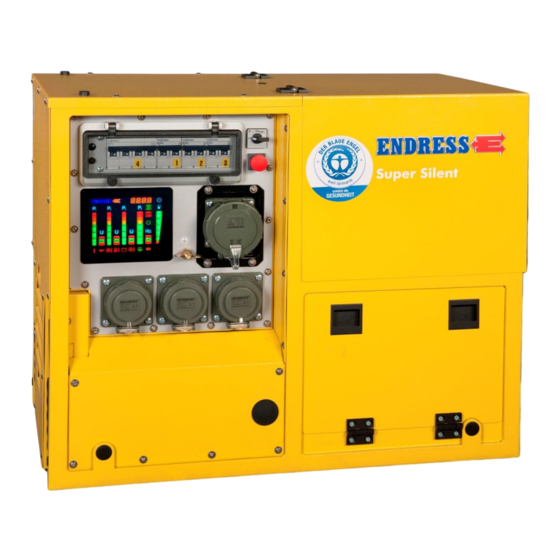
- Page 1 OPERATING INSTRUCTIONS ESE 608 DHG ES DI DIN SILENT Article No.: 151312 / 156312...
- Page 2 E133863 Publication date January 2013 Copyright © 2013, ENDRESS Elektrogerätebau GmbH This documentation and parts thereof are subject to copy- right. Any use or modification beyond the restrictions of the Copyright Act is forbidden and subject to penalty without the consent of ENDRESS Elektrogerätebau GmbH.
- Page 3 Contents Table of Contents List of illustrations List of tables Status at: January 2013...
-
Page 4: General Information
1 General information These operating instructions must be read carefully and un- derstood before using the generator. These operating instructions are intended to familiarise you with the basic operation of the generator. These operating instructions contain important information on using the generator safely and appropriately. Complying with this information helps to: ... - Page 5 1.1 Documentation / scope of delivery In addition to this document, there are the following docu- ments and standard accessories for the ESE 608 DHG ES DI DIN SILENT generator. Cable with test tip (see Figure 1-1-(1)) Tools (see Figure 1-1-(2)) ...
-
Page 6: Safety Symbols
1.2 Safety symbols The safety warning symbol indicates that a source of danger exists. General hazard This warning symbol indicates activities where several caus- es can lead to risks. Potentially explosive materials This warning symbol indicates activities during which there is an explosive hazard, possibly with lethal consequences. -
Page 7: General Safety Regulations
Whoever operates the generator or works with it must read this chapter and comply with its regulations in practice. 2.1 Important safety warning ENDRESS generators are designed to operate electrical equipment with appropriate power output requirements. Oth- er applications can lead to injury to the operating personnel and to damage to the generator as well as other damage to equipment. - Page 8 The following actions are not permitted. Operation in explosion-prone environments Operation in fire-prone environments Operation in confined areas Operation from a vehicle platform that has not been swung out Operation without the necessary safety redundancies ...
- Page 9 Every inappropriate use or all activities on the generator which are not described in these instructions are forbidden misuse outside the legally defined limits of liability of the manufacturer. 2.1.2 Foreseeable incorrect use or inappropriate handling Foreseeable incorrect use or inappropriate handling of the generator nullifies the manufacturer's EC Declaration of Con- formity and automatically thereby the operating licence.
- Page 10 2.1.3 Residual risks Before design and planning were begun, the residual risks of the ESE 608 DHG ES DI DIN SILENT generator were ana- lysed and evaluated by means of a hazard analysis. Structurally unavoidable residual risks during the entire ser-...
- Page 11 Environmental hazards Environmental hazards involving the generator may be caused by: Inappropriate handling Operating fluids (fuel, lubricants, engine oil, etc.) Exhaust gas emission Noise emission Fire hazard Material damage to the Material damage to the generator can occur through: generator ...
-
Page 12: Personal Protective Equipment
2.2 Operating personnel – Qualification and obligations Only appropriately authorised personnel may work with or on the generator. The authorised operating personnel must: be at least 18 years old. be trained in first aid and able to provide it. ... - Page 13 2.4 Danger zones and work areas The danger zones and work places (work areas) around the generator are determined by the activities to be undertaken within the individual life cycles: Life cycle Activity Danger zone Work area Transport in the vehicle Radius of 1.0 m none by the operating person-...
- Page 14 2.5 Signs on the generator These signs must be fitted on the generator and be kept in a clearly legible condition: Fig. 2-1: Signs on the generator Version: January 2013...
- Page 15 Number Sign Name Noise emission Note Line extension Potential equalization (earthing for FI) Reference note - read operating instructions Nameplate Generator Note Hot surfaces Fuel note Note Open flame prohibited Fuel note Table 2.2: Signs on the generator Status at: January 2013...
-
Page 16: General Safety Instructions
2.6 General safety instructions The generator's construction may not be modified in any way. The motor's nominal rpm has been set in the factory and may not be changed. All protective covers must be at hand and functional. All signs on the generator must be in place and be in a clear- ly legible condition. - Page 17 Open flames and light are prohibited in the generator's dan- ger zone. Consuming alcohol, drugs, medicines, or other conscious- ness-expanding and/or changing substances is prohibited. The authorised personnel must be familiar with the generator components and their function and know how to use them. Transport The generator is only be transported after it has cooled down.
- Page 18 It is prohibited to operate the generator without air filters and with an opened air filter cover. The generator must always be operated with the hood closed. Refuelling It is prohibited to refill the generator's fuel tank during opera- tion. It is prohibited to refill the fuel tank on the generator when it is still hot.
- Page 19 Maintenance and repair Operating personnel may only carry out the maintenance or work repair work described in these operating instructions. All other maintenance or repair tasks may only be carried out by specially trained and authorised specialists. Always disconnect the starter battery before beginning maintenance and/or repair work.
- Page 20 Notes Version: January 2013...
- Page 21 3 Integral components of ESE 608 DHG ES DI DIN Silent 3.1 Operation/engine side Figure 3-1: Components on the operating and engine side Engine Cap for external refuelling Tank cover Feed air to the engine (always keep free) Recoil starter Flap for engine below Oil level Status at: January 2013...
- Page 22 3.2 Rear / generator side Figure 3-2: Electrical compartment components Flap for engine below Feed air to the engine (always keep free) Exhaust Carrying handle Version: January 2013...
-
Page 23: Control Panel
3.3 Control panel Figure 3-3: Control panel components START-STOP switch CEE socket Circuit breaker (under hinged window) Potential equalization (earthing for FI) Protective earthing conductor test Schuko (shockproof) power sockets (valid for devices up to year of construction 12/2015) Multi-functional display Status at: January 2013... - Page 24 3.4 Function and mode of operation Function and mode of operation The synchronous generator is firmly coupled to the drive engine. The assembly is installed in a stable frame and equipped with a flexible, low-vibration suspension. Splash-proof earthed power and CEE sockets with a nominal voltage of 230 and/or 400 V/50 Hz supply the power.
- Page 25 Notes: Status at: January 2013...
- Page 26 4 Operating the ESE 608 DHG ES DI DIN SILENT The operation of the generator is described in this section. 4.1 Transport Proceed as follows to transport the generator. Requirements These requirements must be met: The generator must be turned off ...
- Page 27 Fig. 4-1: Ring screw for loading Transporting with a crane Screw on the ring screw for loading / check for firm seat- ing. Hook in hook for the crane onto the eye of the generator. Transport with the crane to the use location. Slowly lower the device and remove the hooks.
- Page 28 4.2 fuelling Proceed as follows to refuel the generator. Requirements These requirements must be met: The device must be shut off. The device must be cooled down. Adequate ventilation must always be available WARNING! Escaping motor oil or diesel fuel can burn. ...
- Page 29 Figure 4-2: External refuelling Refuelling the device A max. suction height of 1 m is allowed. externally Remove cover plug (see Figure 4-2-(2)) Place hose for external refuelling canister with quick- connect coupling LP-006 on cou- (see Figure 4-2-(1)). Put pling (see Figure 4-2-(1)) ...
- Page 30 4.3 Commissioning Requirements These requirements must be met: Electrical safety check (see 5.3) there must be fuel in the tank. an adequate oil level (for this, see the engine's operating and maintenance manual (see Figure 1-1-(5)) Adequate ventilation must always be available ...
- Page 31 Starting the motor Start the engine as follows: Fig. 4-3: Started by hand: into the “RUN” HAND START 1. Move START-STOP switch (Fig. 4-3-(2)) position. 2. Advance engine at the handgrip of the reversing starter (Fig. 4-3-(1)) NOTE Support oneself with one hand on the device grip in order to simplify advancing the engine.
- Page 32 4.4 Connecting up to consumers Proceed as follows to connect appliances to the generator. Requirements These requirements must be met: generator started device switched off WARNING! Electric shocks cause injury or death. Do not earth the generator. ...
- Page 33 WARNING! Electric shocks cause injury or death. Do not earth the generator. Do not connect protective conductor to an existing po- tential equalisation line. Do not connect the generator to an existing electrical grid. Check the protective conductor Fig.
- Page 34 4.6 Monitoring the operating status using the multifunction display All LEDs light up for about 2 seconds to allow checking as soon as the START-STOP switchis set to the position “RUN”. The normal operational lighting is then shown after- wards for about 30 seconds. If the engine is not started with- in this period, the E-MCS 4.0 goes into energy saving mode and the display goes dark.
- Page 35 Oil pressure: If the display is red whilst the generator is (see Figure 4-54-(15)) running, the oil pressure is too low and the generator switch- es off automatically or the buzzer sounds; this can be acknowledged using the acknowledgement button. (Buzzer only active for the ordered “Insulation monitoring“, “Firecan“) spe- cial fitting Engine temperature:...
- Page 36 If the display is red for single phase utilisation (asymmetric load) then the load should be distributed evenly over the 3 existing phases. Load (P∑) Relative load indicator: (see Figure 4-4-(7)) For a 1 and 3 phase load the total load on the generator is displayed in steps of 10%.
-
Page 37: Insulation Monitoring
4.7 Insulation monitoring The insulation monitoring option can only be supplied by the factory. Figure 4-6: Insulation monitoring using E-MCS 4.0 4.7.1 Insulation monitoring without switching off (Standard for a DIN generator) Requirements The following requirements must be met: Generator has been started (see Fehler! Verweisquelle konnte nicht gefunden werden.) Testing the insulation... - Page 38 1. The reset button must be pressed (see Figure 4-65-(2)) after the test has been completed so that the unit can be used again. Insulation monitoring 1. Plug in the device and switch on. whilst running: The displayed symbol indicates the re- (see Figure 4-5-(8)) sult:...
- Page 39 4. The circuit breaker must be returned to Pos. 1 after the test has been completed and the generator must be re- started so that it can be used again. Insulation monitoring 1. Plug in the device and switch on. whilst running: ...
- Page 40 4.8 Remote start device Proceed as follows to operate the generator using the re- mote start device. Requirements The following requirements must be met: generator is ready for operation Connecting up a remote Connect up the remote start device as follows (with the CAN plug): start device Fig.
- Page 41 Disconnecting the remote Disconnect the remote start device as follows: start device 1. Unlock the plug of the connecting cable for the remote start operating status / generator and then pull the plug out. 2. Screw any protective cap present onto the remote start socket.
- Page 42 Figure 4-7: FI protection switch Checking the FI protection 1. The generator must be started. switch: 2. Put the protection switch into position 1. (seeFigure 4-7-(20)) 3. Activate the test switch (seeFigure 4-7-(10)) The switch position displays the result (seeFigure 4-7-(20)) Symbol Significance...
- Page 43 Observe all local laws and regulations concerning correct disposal of such parts and substances. Your author- ised ENDRESS generator dealer is happy to advise you. Please observe the pertinent environmental protection regu- lations when disposing of the old oil. We recommend bring- ing the oil in a closed container to an old oil collection centre for disposal.
- Page 44 Notes Version: January 2013...
-
Page 45: Maintenance Plan
5 Maintenance Generator maintenance is described in this section. Only personnel from the manufacturer or an authorised spe- cialist workshop may carry out maintenance or repair work not described in this section. 5.1 Maintenance plan Perform maintenance according to the information in the engine manual. - Page 46 Fig. 5-1: Drain the oil. Drain the oil. Lift the device using a crane Remove the plate for the oil drain (see Fig. 5-1-(2)) Guide the drain hose through the open- (seeFigure 1-1 (8)) ing in the frame and set the oil collection pan in place. Screw off the motor's oil drain valve cap (seeFig.
- Page 47 5.3 Checking the electrical safety Only specifically authorised personnel may check the electri- cal reliability. The electrical reliability must be checked in accordance with the applicable VDE regulations, EN and DIN standards and especially the current version of the BGV A3 accident pre- vention regulations.
-
Page 48: Troubleshooting
6 Troubleshooting This section describes problems during operation that au- thorized personnel can remove. Inform yourself further in the engine operating manual. Each occurring problem is described with its possible cause and the respective corrective measure. Malfunction Possible cause Correction No or insufficient voltage availa- The rotational speed of the en- Call service staff. - Page 49 Notes: Status at: January 2013...
-
Page 50: Technical Specifications
7 Technical specifications The technical specifications concerning use of the generator are described in this section. Fig. 7-1: Generator dimensions Version: January 2013... - Page 51 Technical specifications Name Value Unit Type ESE 608 DHG ES DI DIN SILENT Nominal output 400V / 3~ [kVA] Nominal output 230V / 1~ [kVA] Nominal power factor V3~ [cosφ] Nominal power factor V1~ [cosφ] Nominal frequency [Hz] Nominal speed 3000 [min Nominal voltage 3~...
- Page 52 Ambient conditions Name Value Unit Setting up height above sea level < 100 Temperature < 27 [°C] Relative air humidity < 60 Table 7.2: Ambient conditions for the generator Reduced power Power reduction for each addi- Unit tional [°C] Table 7.3: Generator power reduction dependent on ambient conditions Distribution network Line max.
-
Page 53: Replacement Parts
8 Replacement parts This section contains the replacement parts needed to run the generator. 8.1 Frame with engine and generator Fig. 8-1: Replacementparts for the exhaust or generator side Status at: January 2013... - Page 54 Fig. 8-2: Engine and exhaust side replacement parts Item Part number Quantity Article name E506100/99 Frame E505716/99 Engine hood E133683 1B50/10HP engine E130959 Gen syn. 7 kVA IP 54 50Hz E133301 Vibration dampers E505724/99 Engine air duct E133823 Inset handle made of soft PVC E133316 Lamellar plugs 27x0.8-3 E133023...
- Page 55 Item Part number Quantity Article name E505709/11 Protective plate E505732/11 Protective plate 8.2 Electronics Fig. 8-3: Replacement parts for the electrical junction box Item Part number Quantity Article name E505229/96 Front panel E131942 START-STOP switch E130422 Hinged window 162314 Multifunctional control system complete E503857/96 Control panel V1 holder E130424...
Need help?
Do you have a question about the ESE 608 DHG ES DI DIN SILENT and is the answer not in the manual?
Questions and answers