
Related Manuals for Endress ESE 3000 i


Summary of Contents for Endress ESE 3000 i
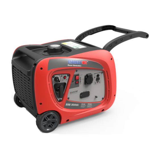
- Page 1 ESE power generator TRANSLATION OF THE OPERATING INSTRUCTIONS ESE 3000 i Article-No. 110 006...
- Page 2 This documentation and parts thereof are subject to copyright. Any use or modi- fication beyond the restrictions of the Copyright Act is forbidden and subject to penalty without the consent of ENDRESS Elektrogerätebau GmbH. This applies in particular to copies, translations, microfilming, as well as storage and processing in electronic systems.
-
Page 3: Table Of Contents
Welcome to ENDRESS! ........ - Page 4 Cleaning the spark screen..........50 Cleaning the power generator .
-
Page 5: Directories
Directories Directories List of illustrations Fig. 3-1 Example of a type plate Fig. 3-2 included in delivery Fig. 3-3 Labels on the device Fig. 6-1 Views of the generator Fig. 6-2 Components on the intake and operating side Fig. 6-3 Components on the exhaust and maintenance side Fig. -
Page 6: About This Manual
About this manual About this manual Through publication of this operating manual we wish to describe and ex- plain your power generator and its use in the best possible way. In doing so we have oriented ourselves on the latest European standard DIN EN 82079-1 when creating this operating manuals. - Page 7 About this manual Safety symbols These warning notices are usually used in a safety symbol which also emphasis- es the type of danger; see next example. A list of the safety symbols used in this operating manual can be found in Chapter Fig. 3-1 . The safety symbols never stand alone.
-
Page 8: Product Identification
Product identification Product identification Welcome to ENDRESS! We are pleased that you have made the decision to purchase a ENDRESS power generator. You have purchased a high-performance product into which we have embodied decades of our experience and have integrated many functions oriented on daily use. -
Page 9: Foreseeable Misuse
Product identification The generator is not to be connected up to other energy distribution systems (e.g. public power supply) or to other energy generation systems (e.g. other gen- erators, solar plant, etc.). Your generator consists of an inverter alternator which is driven by an internal combustion engine firmly screwed to it. - Page 10 Product identification • Never operate the generator in rooms, narrow pits or vehicles. The combus- tion exhaust gases contain poisonous substances including the odourless but deadly gas carbon monoxide (CO) which, when breathed in, can accu- mulate in cases of poor air circulation to reach deadly concentrations. Also a lack of fresh air circulation leads to overheating and possible damage to the generator right through to destruction.
-
Page 11: Scope Of Delivery Of Your Generator
Product identification Scope of delivery of your generator Apart from the technical documentation mentioned in Chapter the following arti- cles are Scope of delivery of your generator: Fig. 3-2 included in delivery Pos. Name Filling funnel for changing oil Spark plug wrench Battery charging cable Operating manual and supplier documentation Screwdriver... -
Page 12: Labels On The Generator
Product identification Labels on the generator An important part of the operating manual is in the form of labelling and notices on your generator. This The label must not be removed and must always be maintained in a legible condition. In a case of damage to the Labels can be or- dered from our customer service team. -
Page 13: Tab. 3-1 Labels On The Device
Product identification Pos. Label Significance Hot surfaces! Do not touch while operating Potential equalization (earthing for RCD) Note Noise emissions Poisonous exhaust gases Never operate in rooms or pits! Note No naked flames Maintenance notes for the engine Note concerning oil level checking and the filling amount Note on reading operating... -
Page 14: For Your Safety
For your safety For your safety The following chapter describes basic Safety instructions for safe operation of your generator. Your device is a very high-performance electrical machine which is potentially dangerous when operated if it has not been installed, commis- sioned, used, serviced and repaired according to the operating manual. - Page 15 For your safety Warning of corrosive substances This warning symbol indicates activities where a risk of chemical burns to the en- vironment as well as people exists, possibly with lethal consequences. Warning of environmentally damaging substances This warning symbol indicates activities where a risk of contaminating the envi- ronment exists, possibly with catastrophic consequences.
-
Page 16: General Safety Instructions
Residual risks As a manufacturer of EU-compliant machines, ENDRESS make great ef- forts to create designs which already eliminate possible risk potentials at the design stage. If this is not possible without significantly impairing the functions of a device, we implement suitable protective measures protect the user from injury. - Page 17 For your safety danger. Exactly impress upon yourself the identification marking of the four different danger levels in order to be able to reliably assess the dan- gers associated with the individual operating states and action steps when reading the operating manual. DANGER! DANGER describes a danger which represents a high level of risk,which can lead to death or severe injuries,when not avoided.
- Page 18 For your safety DANGER! Engine exhaust gases contain poisonous and partially invisible gases such as carbon monoxide (CO) and carbon dioxide (CO2). Risk of death due to poisoning or asphyxiation. ► Ensure that there is good ventilation during the whole period of operation. ►...
- Page 19 For your safety WARNING! Escaping corrosive acid fumes or sulphuric acid during and after the charging process. A risk of suffering severe or even deadly burns. ► Only work with acid-resistant protective equipment. ► Clean surfaces covered in acid immediately using adequate amounts of wa- ter.
- Page 20 For your safety NOTICE! Leaking engine oil and operating fluids can contaminate the soil and groundwater. ► Ensure that the generator is transported horizontally and mounted. ► Make all efforts, at all costs, to prevent escaping of operating fluids. ► Dispose of contaminated soil immediately and according to regulations. NOTICE! Use of wrong or outdated fuel damages or destroys the engine.
-
Page 21: Authorised Operating Personnel - Qualifications And Obligations
For your safety Authorised operating personnel – qualifications and obligations Your generators is a complex machine, the operation and maintenance of which requires exact knowledge of its functions and danger potentials. Therefore any work with or on the device, of any kind, may only be per- formed by authorised and instructed operating personnel. - Page 22 For your safety...
-
Page 23: Checking The Electrical Safety
Checking the electrical safety Checking the electrical safety Checking of electrical safety requires different measures to be taken which may only be undertaken by respectively authorised personnel. In doing so the respective, pertinent VDE provisions, EN and DIN standards, in their re- spectively valid versions, must be observed. -
Page 24: Description Of The Device
Description of the device Description of the device Views The following section provides an overview of the designation and location of the most important components of your generator. It is important to make oneself familiar with these in order to further understand the de- scribed functions and operating steps and to be able to perform these safe- ly. -
Page 25: Important Components Of The Intake And Operation Side
Description of the device Important components of the intake and opera- tion side Fig. 6-2 Components on the intake and operating side Transport grip Tank cover with Tank ventilation Transport grip, retractable Control panel Choke pull Fuel valve Grab handle Cable pull starter Transport wheels Air grille for intake and cooling... -
Page 26: Important Components Of The Exhaust And Maintenance Side
Description of the device Important components of the exhaust and main- tenance side Fig. 6-3 Components on the exhaust and maintenance side Transport grip, retractable Transport grip, Exhaust gas outlet Feet Maintenance flap Oil filling screw with Oil dipstick Oil drain screw Spark plug connector Engine air filter... -
Page 27: Control Panel Components
Description of the device Control panel components Fig. 6-4 Components on the control panel ECO-mode economy circuit Engine starter switch Operating status indicator Schuko socket for 230 V / 16 A / 1~ Safety switch for external battery Battery charge socket for 12V / 8A DC charging USB charge socket with an indicator light Multi-functional display... -
Page 28: Commissioning
Commissioning Commissioning The following chapter describes the basic procedure for first time or re- peated putting into operation of the generator. Follow the working steps de- scribed below when you put your generator into operation for the first time or restart it again after transporting it. NOTICE! For start-up and operation of a generator on building and assembly sites, Deutsche Gesetzliche Unfallversicherung (DGUV) in DGUV Information... -
Page 29: Transporting And Preparing Your Generator
Commissioning Transporting and preparing your generator The following requirements must be fulfilled before you can transport the gener- ator: Requirements The installation area must have an even and load carrying substrate The generator must be turned off The generator is cooled down ... -
Page 30: Refuelling Your Generator
Commissioning Refuelling your generator Proceed as follows to the generator. Requirements The generator must be turned off The generator has cooled down There must be an adequate air supply and air removal All power consuming equipment must be disconnected or switched off DANGER! Leaking engine oil and fuel can burn or explode. -
Page 31: Starting The Generator
Commissioning Refuelling the gen- 1. Put the fuel valve in position “0“. erator 2. Unscrew the tank cover (Fig. 6-2 3. Insert filler aid into the filler neck. 4. Fill with fuel slowly and evenly. 5. Fill the tank to the maximum at the red bar in order not to overfill the tank. -
Page 32: Fig. 7-3 Operating Controls For An Electrical And A Manual Start
Commissioning NOTICE! Your generators will be delivered without any engine oil in it. ► You must fill the engine with engine oil before using it for the first time as de- scribed in Chapter 9.3.2 . Electrical start 1. Turn the tank ventilation valve on the tank cover Fig. 6-2 into the "ON"... -
Page 33: Turning Off Your Power Generator
Commissioning A hand start 1. Turn the tank ventilation valve Fig. 6-2 to the position “ON“ on the tank cover. 2. Open the fuel valve by turning the rotary knob into the “I“ position. 3. Pull the choke lever fully for a cold engine, somewhat less for a hot en- gine. -
Page 34: Connection Of Power Consuming Equipment
Commissioning DANGER! Explosion hazard due to escaping fuel or fuel vapours. A risk of suffering severe even deadly burns. ► After stopping the generator, close the fuel valve (fuel feed) as soon as pos- sible. ► Close the fuel valve (fuel feed) at the latest after ceasing to use the device. BEFORE transport. - Page 35 Commissioning...
- Page 36 Commissioning NOTES...
-
Page 37: The Device In-Use
The device in-use The device in-use Operation of the ECD 03 multi-functional display The control displays allow one to display the various operating states of the generator. The display starts automatically as soon as the generator has started. Fig. 8-1 ECD 03 multifunction display 1. - Page 38 The device in-use Switching on Switch the idle engine speed reduction as follows: ECOtronic 1. Bring the rocker switch Fig. 7-3 into the "I“ (ON) position. Idle down is activated. The engine speed will drop significantly when a consumer is being run at a low power or is switched off. Turning off Switch the idle down off as follows: ECOtronic...
-
Page 39: Maintenance
Contact your dealer or our service hotline +49 (0) 7123 9737-44 service@endress-stromerzeuger.de NOTICE! Please note that, in the case of a concluded warranty agreement, you will lose all rights to make claims if your generator is not serviced according to manufacturer regulations. -
Page 40: Maintenance Work
Maintenance Maintenance work Maintenance interval according to time or operating hours [h] Item Maintenance step Every 8 every 3 every 6 annual- h /daily months months ly every or 25h or 50h 100 h Check for leaktightness, fas- ten, if necessary, change seals Exhaust system Check the spark screen, clean;... -
Page 41: Engine Oil
Maintenance Engine oil The drive motor for your generator, like every internal combustion engine, requires the required engine oil for cooling and inner cooling. It is also im- portant to use the correct oil, both for refilling and changing oil, and to ob- serve the prescribed maintenance intervals. -
Page 42: Fig. 9-2 Checking And Changing Engine Oil
Maintenance CAUTION! The engine and operating equipment on the generator can get very hot while running. Risk of burns ► Never touch any engine parts (in particular the exhaust system) for a few min- utes after ceasing operation. ► Allow the engine to cool off for at least five minutes before changing or check- ing the engine oil. -
Page 43: Changing The Engine Oil
Maintenance Fig. 9-4 Filling tool Refill engine oil If the oil level is too low, instigate the next steps to correct the level. 1. Make ready the engine oil to top up with. 2. Lead the filling funnel also supplied into the previously opened filling opening of the engine (see Fig. -
Page 44: Maintenance Of The Air Filter
Maintenance Place the generator in such a way that a suitable catching pan can be placed under the oil drain screw. Ensure that the generator is mounted horizontally. Wait after previous operation for at least five minutes before changing the oil to allow the oil to flow into the oil sump and for the engine oil to cool off. -
Page 45: Fig. 9-5 Air Filter Behind The Ventilation Grille (Removed)
Maintenance Fig. 9-5 Air filter behind the ventilation grille (removed) Change the air filter 1. Loosen the six screws to remove the ventilation grille Fig. 6-2 and to make insert the air filter housing Fig. 9-5 accessible. 2. Open both fastening clamps Fig. 9-6 - and pull off the air filter cover Fig. -
Page 46: Spark Plug Maintenance
Maintenance Fig. 9-6 Removing the air filter insert Spark plug maintenance The spark plug must be checked every 100 operating hours, at least how- ever once a year, and replaced if necessary. Wrong adjusted, soiled or worn spark plugs can have a negative effect on the starting behaviour, engine running, fuel consumption and pollutant emissions. -
Page 47: Fig. 9-7 Remove Spark Plug
Maintenance Fig. 9-7 Remove spark plug Remove spark plug 1. Loosen the four screws on the maintenance flap Fig. 6-3 and remove the maintenance flap. 2. Pull the spark plug connector Fig. 9-7 - of the spark plug. To do this always pull directly on the plug, never on the ignition cable! 3. -
Page 48: Starter Battery
Maintenance Installing the spark 1. Turn the checked spark plug clockwise by hand into the spark plug on the plug engine (see Fig. Fig. 9-7 - ). Ensure that it is inserted without tilting, not to damage the thread. 2. Tighten the spark plug using the spark plug wrench supplied. 3. -
Page 49: Replacing The Battery
Maintenance 6. Install the starter battery again in the generator (see Chapter 9.6.2 ). The starter battery is charged. If the generator cannot be started after fully charging the battery, there is a defect in the starter power circuit of the generator. Contact your service partner. NOTICE! The starter battery from the factory is maintenance-free throughout its en- tire service life. -
Page 50: Cleaning The Spark Screen
Maintenance Installing the start- 1. Make ready a new starter battery (Observe the instructions from the battery er battery manufacturer. 2. FIRST fasten the red cable Fig. 9-9 - to the positive pole of the battery. 3. THEN fasten the black cable Fig. 9-9 - to the negative pole of the battery. -
Page 51: Cleaning The Power Generator
Maintenance 5. If the spark screen does not need replacing, clean it thoroughly with the aid of the wire brush. 6. Perform steps 1 to 3 in reverse order in order to fasten the spark screen again. The spark screen is serviced. The generator can be put into operation again. Cleaning the power generator Keep your generators clean and dry to ensure safe use at all times and a long service life. -
Page 52: 10 Storage
Storage 10 Storage It is important to store the device at a suitable storage location as soon as your generator is no longer being used. • The storage location must be roofed and must not be subjected to standing water, aggressive vapours or soiling as well as major accumulation of dust. •... -
Page 53: 11 Disposal
Pure b2b devices (devices which, for appropriate use, or exclusively are only used the commercial area) must not be disposed of over public collecting points in Germany and further EU countries. Speak to your authorised ENDRESS gen- erator dealer about handing back your recycling waste electrical equipment. The dealer is also your point of contact for any differing regulations on the respective country of deployment. -
Page 54: 12 Troubleshooting
Troubleshooting 12 Troubleshooting The following table is an aid for you to use in a case where faults arise during use. Based on experience a number of malfunctions can already be removed by operating personnel or the possible causes limited. In all other cases contact your service partner as described in the table. -
Page 55: Tab. 12-1 Troubleshooting
Troubleshooting Malfunction possible cause Correction Fuel level too low Top up with fuel The fuel filter is clogged. Replace the fuel filter. Engine oil level too low (oil lack auto- Bring the engine oil level up to The engine starts but stops matic switch-off) the maximum again shortly afterwards... - Page 56 Troubleshooting Please contact our customer service for further fault diagnosis as well as pro- curement of original spare parts and wear parts at Tel. +49-(0)-7123-9737-44 service@endress-stromerzeuger.de or www.endressparts.com (see Chapter 14 )
-
Page 57: 13 Technical Data
Technical data 13 Technical data The following table contains the technical data for your generator. -
Page 58: Tab. 13-1 Generator Technical Data
Technical data Name Value Unit ESE 3000 i Type of alternator Inverter Maximum output [[LTP] 3.300 Continuous output [PRP] 3.000 Nominal output factor [cosφ] Nominal frequency [Hz] Nominal speed 3.800 [min Nominal voltage ~1 Nominal current ~1 DC output (battery charging) 12 / 8.3... -
Page 59: 14 Replacement Parts
Replacement parts 14 Replacement parts Maintenance and replacement parts can be obtained quickly and easily from your responsible ENDRESS service partner or ENDRESS dealer. You can alternatively obtain support from our central customer service by telephone: +49 (0) 71239737-44 by email: service@endress-stromerzeuger.de Have the item and serial number of your device ready for identification. - Page 60 Replacement parts NOTES...
- Page 61 Replacement parts NOTES...
-
Page 62: Keyword Index
Replacement parts Keyword index Operational indicator light 27 Air filter 26 Potential equalisation device 27 Potential equalization device 23 Battery charge socket 27 Battery charging cable 11 refuel 30 Cable pull starter 25 Carrying handle 29 safety instructions 14 Choke pull 25 Safety switch 27 Control panel 25 Safety symbols 14... - Page 63 Elektrogerätebau GmbH Neckartenzlinger Str. 39 D-72658 Bempflingen, Germany Tel: +49 (0) 7123 /9737-0 Fax: +49 (0) 7123 /9737-50 Email: info@endress-stromerzeuger.de www: www.endress-stromerzeuger.de © 2019, ENDRESS Elektrogerätebau GmbH...
Need help?
Do you have a question about the ESE 3000 i and is the answer not in the manual?
Questions and answers