
Related Manuals for Endress ESE 1408


Summary of Contents for Endress ESE 1408
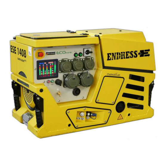
- Page 1 ESE generators TRANSLATION OF THE ORIGINAL OPER- ATING MANUAL ESE 1408 DBG ES DIN Article No. 156519...
- Page 2 This documentation and parts thereof are subject to copyright. Any use or modi- fication beyond the restrictions of the Copyright Act is forbidden and subject to penalty without the consent of ENDRESS Elektrogerätebau GmbH. This applies in particular to copies, translations, microfilming, as well as storage and processing in electronic systems.
-
Page 3: Table Of Contents
Welcome to ENDRESS! ........ - Page 4 9.1.1 DIN 14690 12V connection for maintaining the charge..... .56 9.1.2 BEOS charging current socket ........57 9.1.3 MagCode charging current socket .
-
Page 5: Directories
Directories Directories List of illustrations Fig. 3-1 Example of a type plate Fig. 3-2 Included with delivery Fig. 3-3 Document and tool kit compartment Fig. 3-4 Special accessories Fig. 3-5 Labels on the device Fig. 6-1 Views of the generator Fig. - Page 6 Directories Fig. 15-1 Spare parts over endressparts.com List of tables Tab. 3-1 Labels on the device Tab. 4-1 Danger zone on Generators Tab. 5-1 Recommended test intervals Tab. 13-1 Troubleshooting Tab. 14-1 Power generator technical data...
-
Page 7: About This Manual
About this manual About this manual We would like to explain to you the safe and correct use of your generator in the best possible way through this operating manual. To do this we have oriented ourselves to the new European standard DIN EN 82079-1 for preparing the user manuals. -
Page 8: Using This Operating Manual
About this manual Using this operating manual In order to increase the legibility, comprehensibility and transparency of the document, certain information is highlighted or identified according a uniform system. The following particularly belong in this category: signs warning a bout dangers to life and limb Safety and warning notices are necessary at all locations where there is potential danger from the device which cannot be eliminated by design or operational measures. - Page 9 About this manual Symbols and formatting in the text In order to increase the legibility, comprehensibility and transparency of the doc- ument, various information and activities are awarded uniformly repeating bullets or formatting. The following example shows presentation of a sequence of ac- tions with established work steps: Example: ...
-
Page 10: Product Identification
Product identification Product identification Welcome to ENDRESS! We are pleased that you have made the decision to purchase a ENDRESS power generator. You have purchased a high-performance product into which we have embodied decades of our experience and have integrated many functions oriented on daily use. -
Page 11: Foreseeable Misuse
Product identification The generator is only to be used outdoors within the indicated voltage, output, and nominal RPM ranges (see type plate). You are also allowed to use it on a vehicle extension platform or swivelling com- partment when it is extended or swivelled out. The condition here is that air must be able to flow around the generator unhindered on all sides and, in particular, that discharging its exhaust is ensured. - Page 12 Product identification • The generator is never to be connected up to another energy distribution sys- tem (e.g. public power supply) or to other power generating systems (e.g. other generators, solar plants, etc.). To start with this is usually not permitted by .
-
Page 13: Scope Of Delivery Of Your Generator
Product identification Scope of delivery of your generator Apart from the technical documentation mentioned in Chapter 2.1 the following articles are Scope of delivery of your generator: Included with deliv- Fig. 3-2 Included with delivery Item Name Spark plug wrench Operating manual and supplier documentation Spare2 x spark plugs These supplied products can be found in a separate storage compartment... - Page 14 Product identification Fig. 3-3 Document and tool kit compartment Special accesso- ries The following articles are supplied as special accessories: Fig. 3-4 Special accessories Item Name Refuelling device Standard 20 litre fuel can 150 cm / Ø 50 mm exhaust hose as per DIN 14572...
-
Page 15: Labels On The Generator
Product identification Labels on the generator Important parts of the operating manual can be found as labels and notices fitted on your generator. These labels must not be removed and must always be main- tained in a legible condition. In the event of damage, new labels can be ordered from our customer service team. - Page 16 Product identification Item Name Meaning Remote-controlled unit starts up without a warning Note: Do not touch! - Hot surface when running Note No naked flames Note Fuel quality and Tank capacity Type plate Refers to the line network’s maximum extension Note Read the operating manual before starting up...
-
Page 17: For Your Safety
For your safety For your safety The following chapter describes basic Safety instructions for safe operation of your generator. Your device is a very high-performance electrical machine which is potentially dangerous when operated if it has not been installed, commis- sioned, used, serviced and repaired according to the operating manual. - Page 18 For your safety Warning of corrosive substances This warning symbol indicates activities where a risk of chemical burns to the en- vironment as well as people exists, possibly with lethal consequences. Warning of environmentally damaging substances This warning symbol indicates activities where a risk of contaminating the envi- ronment exists, possibly with catastrophic consequences.
-
Page 19: General Safety Instructions
Residual risks As a manufacturer of EU-compliant machines, ENDRESS make great ef- forts to create designs which already eliminate possible risk potentials at the design stage. If this is not possible without significantly impairing the functions of a device, we implement suitable protective measures protect the user from injury. - Page 20 For your safety four different danger levels in order to be able to reliably assess the dan- gers associated with the individual operating states and action steps when reading the operating manual. DANGER! DANGER describes a danger which represents a high level of risk,which can lead to death or severe injuries,when not avoided.
- Page 21 For your safety DANGER! Engine exhaust gases contain poisonous and partially invisible gases such as carbon monoxide (CO) and carbon dioxide (CO2). Risk of death due to poisoning or asphyxiation. ► Ensure that there is good ventilation during the whole period of operation. ►...
- Page 22 For your safety WARNING! Escaping corrosive acid fumes or sulphuric acid during and after the charging process. A risk of suffering severe or even deadly burns. ► Only work with acid-resistant protective equipment. ► Clean surfaces covered in acid immediately using adequate amounts of wa- ter.
- Page 23 For your safety NOTICE! Excessive heat or moisture can destroy the device. ► Always ensure that there is a good supply of air and heat removal. ► Never operate the generator in rooms or narrow pits. ► Never clean the device with the aid of a strong jet of water or high pressure cleaner.
-
Page 24: Authorised Operating Personnel - Qualifications And Obligations
For your safety Authorised operating personnel – qualifications and obligations Your Generators is a complex machine, the operation and maintenance of which requires exact knowledge of its functions and danger potentials. Therefore any work with or on the device, of any kind, may only be per- formed by authorised and instructed operating personnel. - Page 25 For your safety Product's service life phase Danger zone Transport and installation within a radius of 1m around or below the de- vice Operation within the outer limits of the device Service and maintenance Within the outer limits of the device when switched on Generators Tab.
-
Page 26: Checking The Electrical Safety
Checking the electrical safety Checking the electrical safety Checking the electrical safety needs different measures that are only to be undertaken by authorised personnel. In doing so the pertinent VDE provi- sions, EN and DIN standards, in their valid versions, must be observed. You must abide by additional regulations if it is being used by authorities for or- ganisational and security tasks. - Page 27 Checking the electrical safety When What / how First start-up at the op- • See Chapter 7 and also abide by the operating manual Operating erating location provided by the engine manufacturer personnel • Visual inspection for externally visible defects such as transport damage.
-
Page 28: Description Of The Device
Description of the device Description of the device Views The following section provides an overview of the designation and location of the most important components of your generator. It is important that you familiarise yourself with it so that you will be able to understand and safely carry out the functions and operating steps described below. -
Page 29: Components On The Connecting Side
Description of the device Components on the connecting side Fig. 6-2 Components on the connecting end Filling opening Fuel tank Fuse box with circuit breakers Control panel Fuses / manual protective cover Engine hood Engine cooling exhaust outlet Exhaust outlet (when converted as per Oil filter maintenance hatch Chapter 10.5 ) External connection Refuelling device... -
Page 30: Components On The Maintenance Side
Description of the device Components on the maintenance side Fig. 6-3 Components on the maintenance side Drive engine Exhaust outlet (standard version) Maintenance cover 12V starter battery Engine cooling exhaust outlet Maintenance cover Engine air filter Engine oil filling opening Engine oil dipstick Spark plug connector 20A fuse for 12V power supply... -
Page 31: Control Panel Components
Description of the device Control panel components Fig. 6-4 Control panel and fuse box components EMERGENCY STOP smash button Control panel lighting, ECOtronic On/Off Control panel lighting ON/OFF Engine start switch Test socket Protective earthing conduc- tor test Circuit breaker for 400V CEE socket Circuit breaker for 230V Schuko sockets Schuko16 A sockets CEE/ 16 A / 3~ sockets... - Page 32 Description of the device NOTES...
-
Page 33: Commissioning
Commissioning Commissioning The following chapter describes the basic procedure for first time or re- peated putting into operation of the generator in "On-site operation" mode. Follow the working steps described below when you put your generator into operation for the first time or restart it again after transporting it. Initial start-up Fig. - Page 34 Commissioning Requirements: the ground at the installation site must be even and capable of taking the load the generator must be switched off the generator must be cooled down if fitted, the fuel valve must be in the “OFF” position ...
-
Page 35: Refuelling Your Generator
Commissioning Refuelling your generator Proceed as follows to fit the generator's own tank: the generator. Conditions the generator is turned off the generator has cooled down there must be an adequate air supply and air removal all power consuming equipment must be disconnected or switched off DANGER! Leaking engine oil and fuel can burn or explode. -
Page 36: Starting The Generator
Commissioning Starting the generator How to start the Generators for manual operation with fuel supplied from its own tank is explained here. See Chapter 9.3 for automatic remote start- ing. See Chapter 8.5 for supplying the fuel from an external refuelling de- vice. - Page 37 Commissioning Starting the engine Fig. 7-2 Electrical start controls Electrical start 1. Turn the lever on the fuel valve into the “Tank” position. The generator will be supplied with fuel from its own tank. 2. Turn the engine start switch into the “ON”...
- Page 38 Commissioning Fig. 7-3 Manually starting the recoil starter Manual start 1. Open the engine hood Fig. 7-2 - 2. Turn the lever on the fuel valve Fig. 7-2 into the “Tank” position. The generator will be supplied with fuel from its own tank. 3.
-
Page 39: Turning Off Your Power Generator
Commissioning NOTICE! If the oil pressure warning light on the multifunction display lights up during the start process Fig. 8-1 then the engine's oil level is too low. The automatic low-oil system prevents the motor from starting. ► First refill up to the engine oil level (see Chapter 10.4.1 ), before you restart the engine. -
Page 40: Turn Off Your Generator In The Event Of An Emergency
Commissioning Turn off your generator in the event of an EMER- GENCY Your Generators is fitted with an EMERGENCY-STOP smash button, (this depends on the version) . It enables you to immediately switch the de- vice off in an EMERGENCY. CAUTION! The EMERGENCY-STOP smash button is only to be used in the event of a dangerous situation arising in an emergency. -
Page 41: Connection Of Power Consuming Equipment
Commissioning Connection of power consuming equipment DANGER! Mortal danger due to an electric shock if live parts are touched. ► Never operate the device if it is in a damaged condition. ► Never operate the electrical consumers and connecting cable (power con- suming equipment) in a damaged condition. - Page 42 Commissioning CEE 400V / 16A / 3~ socket CAUTION! Danger due to malfunctioning of the protective measures against hazard- ous shock voltages with an extended supply network! ► Keep the length of the connecting line as short as possible. ► Use as few sub-distributions as possible. ►...
-
Page 43: The Device In-Use
The device in-use The device in-use Multi-function display The E-MCS 4.0 multifunction display enables you to monitor all of the rele- vant operating statuses as well as the status messages. This gives you an overview of many parameters such as current power output, fuel level, op- erating hours, warning messages and more. - Page 44 The device in-use EMERGENCY STOP The display will lights up red if the generator has been stopped by the EMER- GENCY STOP smash button (see Chapter 7.6 ). Light sensor The integrated light sensor controls the display’s brightness depending on the ambient light.
- Page 45 The device in-use Output voltage V for phases L and/or L When the generator is running, the segment display indicates whether the out- put voltages for the relevant L and L phases lie within the permitted toler- ance range. The segment will light up green if it is. If the “high” segment light up red, then the output voltage for the relevant phase is too high;...
-
Page 46: Ecotronic Speed Reduction
The device in-use ECOtronic speed reduction The ECOtronic system ensures that the generator's engine speed is auto- matically reduced to approx. 1,800 min as soon as all of the connected consumers are switched off or disconnected. This extra function is avail- able when the engine is at operating temperature (about 5 minutes after starting the engine). -
Page 47: Insulation Monitoring
The device in-use Insulation monitoring 8.3.1 Standard version, cannot be switched off The insulation monitoring system provides electrical safety for the gener- ator and to all connected consumers and cable connections during contin- uous operation. Acoustic and visual warnings will be generated if an insulation fault oc- curs. - Page 48 The device in-use Signal Meaning Lamp lights red, Insulation monitoring is OK, lamp and warning horn sounding warning horn are also OK. Lamp does not light up, Insulation monitoring is defective or warning horn is silent lamp and warning horn are defective Lamp does not light up, Insulation monitoring is OK...
-
Page 49: Special Version, Can Be Switched Off
The device in-use WARNING! Risk of touching surfaces that are live due to faulty insulation. Danger of electric shock if a second insulation fault occurs. ► The relevant consumable is not to be used any more after an insulation fault has been determined. - Page 50 The device in-use 3. Press the test button The lamp, the warning horn and the circuit breaker’s position Fig. 6-4 and/or show the result of the test: 4. After you have read the test result, you must press the reset button just once.
-
Page 51: Check The Protective Conductor
The device in-use Lamp Result Meaning Lamp lights red Circuit breaker jumps Insulation fault ≤ 23 kΩ warning horn sounding* into its “0/OFF” position is present, a consumer is defective Lamp does not light Circuit breaker stays in Consumer does not its “1/ON”... - Page 52 The device in-use NOTICE! The previously required protective conductor test device has been deleted in the new version of DIN 14685-1: 2015-12, as it is not suitable for running a qualitative test. The test described in this chapter is based on common practice and it can only indicate an interrupted protective conductor con- nection.
- Page 53 The device in-use DANGER! Lethal contact voltage will exist if the protective conductor connection is defective Danger of an electrical shock. ► Never use a consumable with a defective protective conductor connection. WARNING! Electric arcs can occur due to electrostatic charges Danger of being burnt or an explosion ►...
-
Page 54: 3-Way Fuel Valve
The device in-use 3-way fuel valve The 3-way fuel valve gives you the option of switching the fuel supply be- tween your own tank and an external refuelling device during operation. This will prevent you from having to switch off the generator for refuelling during long periods of use. - Page 55 The device in-use Connecting the re- 1. Pull off the dust cap on the 3-way valve connection. fuelling device 2. Press the refuelling device's coupling firmly onto the 3-way valve connec- tion. The coupling will engage with an audible click. 3.
-
Page 56: Optional Fittings
Optional fittings Optional fittings Battery charge maintenance The battery recharger allows you to recharge the starter battery on the gen- erator using an external charging device and this will ensure that you have a full charge at all times. There a various different standardised sockets available for connection which is described as follows. -
Page 57: Beos Charging Current Socket
Optional fittings 4. Turn the plug's locking ring clockwise up to the stop. The connection for recharging the starter battery is established. 9.1.2 BEOS charging current socket Proceed as follows to recharge your Generators’s starter battery using the optional BEOS charging current socket: Fig. -
Page 58: Magcode Charging Current Socket
Optional fittings 9.1.3 MagCode charging current socket Proceed as follows to recharge your Generators’s starter battery using the ® optional MagCode charging current socket: ® Fig. 9-3 MagCode charging current socket Conditions The Generators is ready to operate. The starter battery is connected as specified to the drive engine’s current cir- cuit. -
Page 59: Din 14690 12V Connection
Optional fittings DIN 14690 12V connection Apart from recharging, the 12V connection socket as per DIN 14690 also gives you the option of supplying suitable accessories with a 12V DC volt- age. Proceed as follows to supply an external 12V accessory with power at the 12V connection socket: Fig. -
Page 60: Remote Start Device
Optional fittings Remote start device 9.3.1 HARTING remote starting device The optionally installed HARTING® socket allows you to turn your power generator on and off remotely in connection with a suitable external instal- lation (such as a control station). WARNING! Beware of machines starting in automatic mode. - Page 61 Optional fittings 3. Push the HARTING® plug of the external connection cable onto the HART- ING® socket until the stop. 4. Pull the locking bracket Fig. 9-5 in the direction of the HARTING® plug to lock it in place. 5. Turn the engine start switch Fig. 7-2 into the “ON”...
-
Page 62: Firecan Remote Start Device
Optional fittings 9.3.2 FireCAN remote start device The CPC socket that can be optionally installed with a standard FireCAN, when used in conjunction with a suitable external installation, allows you to remotely control and monitor your generator (e.g. from an emergency vehicle). - Page 63 Optional fittings NOTICE! Only activate the starter briefly (max. 5-10 seconds). Never unclamp the starter battery when the engine is running. When the remote start device is connected up, the generator can NO LON- GER be switched off using the engine start switch Fig. 9-6 .
-
Page 64: Remote Starting Device
Optional fittings Remote starting device The remote starting device enables you to start your generator from an ex- ternal starting device when the starter battery is weak or discharged. To do this you need a suitable 12V DC source (e.g. from the emergency vehicle) and a suitable connection cable ("NATO plug"). - Page 65 Optional fittings 8. Replace the sealing cap Fig. 9-7 on the remote start socket and turn it clockwise to tighten it in place. The remote start process has been completed.
-
Page 66: Residual Current Circuit Breaker (Rcd)
Optional fittings Residual current circuit breaker (RCD) The RCD (Residual Current Device) protects against dangerous body cur- rents in compliance with DIN VDE 0100 0100-551 in networks with a TN-S system. This option is only available ex works. The RCD needs the generator to be earthed in compliance with the regulations so that it can detect a residual current. - Page 67 Optional fittings Testing the RCD 1. You must ensure that the Fig. 9-8 RCD switch is in POS 1. 2. Press the test knobFig. 9-8 The switch position Fig. 9-8 shows you the result (see table below). 3. Turn the switchFig. 9-8 back into POS 1 so that you can operate consum- ers from the generator again.
-
Page 68: Polarity Changer
Optional fittings Polarity changer Three-phase CEE sockets are wired in as the standard fitting for a clock- wise rotating field. The optionally installed polarity changing switch allows you to adapt a specific CEE socket on your power generator to use with consumers with a counter-clockwise rotating field. - Page 69 Optional fittings 4. Turn the polarity changing switch Fig. 9-9 to the correct rotating field. The rotating field has been changed. 5. Now switch the consumer back on. The consumer will be supplied with the correct rotating field.
-
Page 70: Using An Exhaust Hose
Optional fittings Using an exhaust hose The silencer’s exhaust tailpipe has a connection for attaching an optionally available exhaust hose. This will enable you to discharge the engine ex- haust gases away from the generator’s immediate vicinity. DANGER! Engine exhaust gases contain poisonous and partially invisible gases such as carbon monoxide (CO) and carbon dioxide (CO2). - Page 71 Optional fittings Fig. 9-10 Connecting up the exhaust hose Proceed as follows to connect up the optional exhaust gas hose (see Fig. 3-4 ) to your generator: Conditions Generator is ready for operation The generator is switched off. Connecting up the 1.
-
Page 72: 10 Maintenance
Maintenance 10 Maintenance Generators maintenance is described in this section. It may only be per- formed by qualified specialist personnel. Maintenance and repair which is neither described in this operating manual nor in the possibly also delivered operating and maintenance instructions may only be undertaken by authorized service personnel from the manu- facturer. -
Page 73: Starter Battery
Maintenance tenance instructions provided by the engine manufacturer. This operating manual merely describes the instructions that differ from or go beyond those instructions. DANGER! Mortal danger from unintentional generator start up. Danger of burns and being caught by rotating parts. ►... -
Page 74: Replacing The Battery
Maintenance WARNING! There is a risk of explosion and fire in the case of inappropriate handling and spark development when working with the battery. Danger from spraying sulphuric acid. Danger of suffering severe even deadly burns and chemical burns. Danger of being blinded. ►... - Page 75 Maintenance Fig. 10-2 Accessing the starter battery Proceed as follows to change the starter battery: Conditions the generator is switched off 1. Undo the two screws in the maintenance cover Fig. 10-2 and then remove the cover. 2. Remove the heat shield 3.
- Page 76 Maintenance Fig. 10-3 Replacing the starter battery 1. Prepare the new starter battery (follow the battery manufacturer’s handling instructions). 2. Place the starter battery alongside the battery compartment. 3. Attach the red cable to the battery's positive terminal FIRST and then pull the red protective cap over the terminal.
-
Page 77: Engine Oil
Maintenance 10.4 Engine oil The drive motor for your generator, like every internal combustion engine, requires the required engine oil for cooling and inner cooling. It is also very important to use the correct engine oil, both for refilling and when chang- ing the oil, and to adhere the stipulated maintenance intervals. -
Page 78: Changing The Engine Oil
Maintenance wait after previous operation for about five minutes before checking until the engine oil has gathered again in the oil sump to obtain a correct measure- ment. CAUTION! The engine and operating equipment on the generator can get very hot while running. - Page 79 Maintenance CAUTION! The engine and operating equipment on the generator can get very hot while running. Risk of burns ► Never touch any engine parts (in particular the exhaust system) for a few min- utes after ceasing operation. ► Allow the engine to cool off for at least five minutes before changing or check- ing the engine oil.
- Page 80 Maintenance 3. Reach in through the maintenance opening and pull out the drainage hose that is stowed inside out through the opening for the 3-way fuel valve. 4. Place a suitable oil collecting container under the drainage hose. 5. Carefully undo the sealing screw on the drainage hose and ensure that the screw does not fall off.
-
Page 81: Changing The Exhaust Gas Routing
Maintenance 10.5 Changing the exhaust gas routing Your generator has been designed so tha the exhaust gas can be dis- charged from either the maintenance side or the connections end. The ex- haust gas outlet is at the maintenance end ex works. The exhaust gas routing can be changed at any time by trained service personnel. - Page 82 Maintenance 1. Remove the starter battery and heat shield as described in Chapter 10.3.2 . You can now access the exhaust gas routing. 2. Undo and remove both screws from the exhaust gas routing. 3. Remove the sealing plate with the old exhaust gasket between the two flanges (parts marked in red).
- Page 83 Maintenance 6. Remove the two circlips from the exhaust gas outlet on the maintenance side (detail B) 7. Replace the sealing plate that was removed in Step 2 back in the exhaust gas outlet. 8. Ensure that the sieve remains in the exhaust gas pipe. 9.
- Page 84 Maintenance NOTES...
-
Page 85: 11 Storage
Storage 11 Storage It is important to store the device at a suitable storage location as soon as your generator is no longer being used. • The storage location must be roofed and must not be subjected to standing water, aggressive vapours or soiling as well as major accumulation of dust. •... -
Page 86: 12 Disposal
Pure b2b devices (devices which, for appropriate use, or exclusively are only used the commercial area) must not be disposed of over public collecting points in Germany and further EU countries. Speak to your authorised ENDRESS gen- erator dealer about handing back your recycling waste electrical equipment. The dealer is also your point of contact for any differing regulations on the respective country of deployment. -
Page 87: 13 Troubleshooting
Troubleshooting 13 Troubleshooting The following table is an aid for you to use in a case where faults arise during use. Based on experience a number of malfunctions can already be removed by operating personnel or the possible causes limited. In all other cases contact your service partner as described in the table. - Page 88 Customer service: Tel. +49 7123 973744 Email: service@endress-stromerzeuger.de Have the item and serial number of your device ready for identification. You will find these details on the type plate (see Fig. 3-5 ).
-
Page 89: Technical Data
14 Technical data The following table contains the technical data for your generator. Name Value Unit ESE 1408 DBG ES DIN Super Silent Plus Continuous power output [PRP] 3~ 13.7 / 10.9 [kVA / kW] Continuous power output [PRP] 1~ 7.5 / 6.7... -
Page 90: 15 Replacement Parts
Replacement parts 15 Replacement parts Maintenance and replacement parts can be obtained quickly and easily from your responsible ENDRESS service partner or ENDRESS dealer. You can alternatively obtain support from our central customer service by telephone: +49 (0) 71239737-44 by email: service@endress-stromerzeuger.de Have the item and serial number of your device ready for identification. - Page 91 Replacement parts NOTES...
-
Page 92: Keyword Index
Replacement parts Keyword index Numerics HARTING socket 60 62 Home page 90 12V fuses 30 3-way fuel valve 29 Imprint 2 included in the delivery 13 Air filter 30 ISO monitoring 31 Air intake 29 Air intakes 30 Asymmetric load 45 Label 15 15 Automatic low-oil system 44 Light sensor 44... - Page 93 Replacement parts DIN ISO 3864 8 DIN VDE 82079-1 7 ISO 3864 19 ISO 7010 17 standards DIN EN 60204 19 Starter battery 30 starter battery 73 Starting 36 Switching off 39 39 Tank Filling opening 29 Tank capacity 16 tank capacity 16 Temperature warning 44 Test cable 52...
- Page 94 Elektrogerätebau GmbH Neckartenzlinger Str. 39 D-72658 Bempflingen, Germany Tel: +49 (0) 7123 /9737-0 Fax: +49 (0) 7123 /9737-50 Email: info@endress-stromerzeuger.de www: www.endress-stromerzeuger.de © 2018, ENDRESS Elektrogerätebau GmbH...
Need help?
Do you have a question about the ESE 1408 and is the answer not in the manual?
Questions and answers