
Related Manuals for Endress ECO Power Line ESE 3000 BS


Summary of Contents for Endress ECO Power Line ESE 3000 BS
- Page 1 ECO Power Line Generators TRANSLATION OF THE ORIGINAL OPER- ATING MANUAL ESE 3000 BS ESE 6000 BS...
- Page 2 This documentation and parts thereof are subject to copyright. Any use or modi- fication beyond the restrictions of the Copyright Act is forbidden and subject to penalty without the consent of ENDRESS Elektrogerätebau GmbH. This applies in particular to copies, translations, microfilming, as well as storage and processing in electronic systems.
- Page 3 We reserve the right to make modifications in terms of ongoing technical devel- opment. This operating manual does not include technical modifications that oc- curred after printing. The colours in this operating manual do not always comply completely with the actual designs due to technical printing reasons.
-
Page 4: Table Of Contents
Welcome to ENDRESS! ........ - Page 5 Disposal ..............50 Troubleshooting.
-
Page 6: Directories
Directories Directories List of illustrations Fig. 3-1 Example of a type plate Fig. 3-2 included in delivery Fig. 3-3 Labels on the device Fig. 6-1 Generator and control side components Fig. 6-2 Engine and tank side components Fig. 6-3 Control panel components Fig. -
Page 7: About This Manual
About this manual About this manual We would like to explain to you the safe and correct use of your generator in the best possible way through this operating manual. To do this we have oriented ourselves to the new European standard DIN EN 82079-1 for preparing the user manuals. - Page 8 About this manual the required distinctive warning notices at the correct point in time without impair- ing the legibility and comprehensibility of the operating manual. This is according to the regulations contained in the international standard DIN ISO 3864 de- scribes a fixed rule for all safety and warning notices, as shown in the following example.
- Page 9 About this manual Additional notices for operation or for function of a unit are marked with the adjacent symbol. NOTICE! The adjacent symbol is situated anywhere where the supplier documenta- tion must be read and observed and refers to, ► appropriate information, ►...
-
Page 10: Product Identification
Product identification Product identification Welcome to ENDRESS! We are pleased that you have made the decision to purchase a ENDRESS power generator. You have purchased a high-performance product into which we have embodied decades of our experience and have integrated many functions oriented on daily use. -
Page 11: Foreseeable Misuse
Product identification The power generator is designed for manual or use with individual electrical pow- er consuming equipment (according to VDE 100, Part 551). The protective con- ductor assumes the function of the potential equalisation line. A splash-proof protective contact socket with nominal voltage of 230 V / 50 Hz 1~ supplies the power (see Fig. - Page 12 Product identification • Never operate the generator in rooms, narrow pits or vehicles. The combus- tion exhaust gases contain poisonous substances including the odourless but deadly gas carbon monoxide (CO) which, when breathed in, can accu- mulate in cases of poor air circulation to reach deadly concentrations. Also a lack of fresh air circulation leads to overheating and possible damage to the generator right through to destruction.
-
Page 13: Scope Of Delivery Of Your Generator
Product identification Scope of delivery of your generator Apart from the technical documentation mentioned in Chapter 2.1 the following articles are Scope of delivery of your generator: Fig. 3-2 included in delivery Item Name Tool kit Wheel set (optional for ESE 3000BS) -
Page 14: Labels On The Generator
Product identification Labels on the generator An important part of the operating manual is in the form of labelling and notices on your generator. This The label must not be removed and must always be maintained in a legible condition. In a case of damage to the Labels can be or- dered from our customer service team. -
Page 15: Tab. 3-1 Labels On The
Product identification Item Label Significance Warning of hot surfaces Warning about easily inflam- mable liquids Warning of hot surfaces All safety and warning signs Earthing sign Note on fuel tap Choke lever instruction Reference to air filter main- tenance Type plate Tab. -
Page 16: For Your Safety
For your safety For your safety The following chapter describes basic Safety instructions for safe operation of your generator. Your device is a very high-performance electrical machine which is potentially dangerous when operated if it has not been installed, commis- sioned, used, serviced and repaired according to the operating manual. - Page 17 For your safety Warning of corrosive substances This warning symbol indicates activities where a risk of chemical burns to the en- vironment as well as people exists, possibly with lethal consequences. Warning of environmentally damaging substances This warning symbol indicates activities where a risk of contaminating the envi- ronment exists, possibly with catastrophic consequences.
-
Page 18: General Safety Instructions
Residual risks As a manufacturer of EU-compliant machines, ENDRESS make great ef- forts to create designs which already eliminate possible risk potentials at the design stage. If this is not possible without significantly impairing the functions of a device, we implement suitable protective measures protect the user from injury. - Page 19 For your safety danger. Exactly impress upon yourself the identification marking of the four different danger levels in order to be able to reliably assess the dan- gers associated with the individual operating states and action steps when reading the operating manual. DANGER! DANGER describes a danger which represents a high level of risk,which can lead to death or severe injuries,when not avoided.
- Page 20 For your safety DANGER! Engine exhaust gases contain poisonous and partially invisible gases such as carbon monoxide (CO) and carbon dioxide (CO2). Risk of death due to poisoning or asphyxiation. ► Ensure that there is good ventilation during the whole period of operation. ►...
- Page 21 For your safety WARNING! Escaping corrosive acid fumes or sulphuric acid during and after the charging process. A risk of suffering severe or even deadly burns. ► Only work with acid-resistant protective equipment. ► Clean surfaces covered in acid immediately using adequate amounts of wa- ter.
- Page 22 For your safety NOTICE! Leaking engine oil and operating fluids can contaminate the soil and groundwater. ► Ensure that the generator is transported horizontally and mounted. ► Make all efforts, at all costs, to prevent escaping of operating fluids. ► Dispose of contaminated soil immediately and according to regulations. NOTICE! Use of wrong or outdated fuel damages or destroys the engine.
-
Page 23: Authorised Operating Personnel - Qualifications And Obligations
For your safety Authorised operating personnel – qualifications and obligations Your Generators is a complex machine, the operation and maintenance of which requires exact knowledge of its functions and danger potentials. Therefore any work with or on the device, of any kind, may only be per- formed by authorised and instructed operating personnel. -
Page 24: Danger Zones And Work Areas
For your safety Danger zones and work areas In order to be able to consider all of a machine's safety aspects and to com- ply with the safety and health protection requirements of the applicable standards and EU directives, we have assessed the use of your Generators in all of the phases that it will go through during its product service life (product life cycle). -
Page 25: Checking The Electrical Safety
Checking the electrical safety Checking the electrical safety Checking of electrical safety requires different measures to be taken which may only be undertaken by respectively authorised personnel. In doing so the respective, pertinent VDE provisions, EN and DIN standards, in their re- spectively valid versions, must be observed. -
Page 26: Description Of The Device
Description of the device Description of the device Views The following section provides an overview of the name and location of the most important components in your Generatorss. It is important that you become familiar with them in order to understand the functions and oper- ating steps explained below and to be able to implement them safely. -
Page 27: Generator And Control Side Components
Description of the device Generator and control side components Fig. 6-1 Generator and control side components Oil drain screw Oil filling inlet Control panel Tank extendable handle Generator... -
Page 28: Engine And Tank Side Components
Description of the device Engine and tank side components Fig. 6-2 Engine and tank side components Exhaust Carburettor Filler neck Filling level indicator Choke lever Cord grip for starting motor Air filter... -
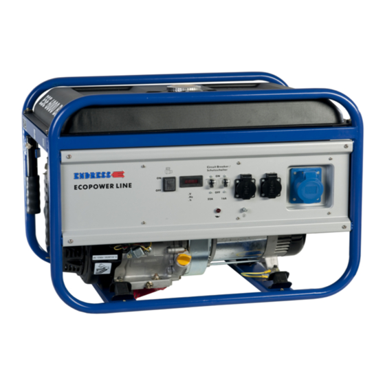
Page 29: Control Panel Components
Description of the device Control panel components Fig. 6-3 Control panel components On and Off switch Operating hours counter Line circuit breaker Electrical safety socket Earthing connection CEE socket... - Page 30 Description of the device NOTES...
-
Page 31: Commissioning
Commissioning Commissioning The following chapter explains the basic procedure for initial or repeated generator start-ups in "Manual" mode. Follow the working steps described below when you put your generator into operation for the first time or re- start it again after transporting it. Transporting and preparing your generator The following requirements must be fulfilled before you can transport the gener- ator:... - Page 32 Commissioning Removing the transport securing devices 1. Undo the fastening screws on the red transport securing device 2. Remove the transport securing device 3. Also perform steps one and two on the opposite sides in order to remove the second transport securing device. Dismantling the transport securing devices is now complete.
-
Page 33: Fitting The Wheel Set
Commissioning Fitting the wheel set How to fit the wheel set on your generator is explained here. The wheel set enables you to transport the generator quicker and with less effort. Two people should be used to fit the wheel set and one of them should hold the device. -
Page 34: Refuelling Your Generator
Commissioning Fig. 7-1 Wheel set parts Refuelling your generator Proceed as follows to refill the generator's own tank: the generator. Requirements: the generator must be turned off the generator has cooled down there must be an adequate air supply and air removal ... -
Page 35: Starting The Generator
Commissioning NOTICE! Use of wrong or outdated fuel damages or destroys the engine. ► Only use the fuel displayed on the sign (Tab. 3-1 ). ► Observe the possibly enclosed documentation for the fuel release of the en- gine manufacturer ►... -
Page 36: Fig. 7-2 Starting The
Commissioning NOTICE! Frequent brief operations and/or long operating times without a load will have a negative effect on the operational readiness and the generator's ser- vice life. ► Try to avoid frequent brief operations, otherwise the starter battery will not be sufficiently charged and it might fail. -
Page 37: Turning Off Your Power Generator
Commissioning 3. Move the choke lever into the "CLOSE" position 4. Switch the generator switch into the "ON" position 5. Pull the cable pull starter out until you feel some resistance and then pull it out vigorously. The engine starts. 6. -
Page 38: Turn Off Your Generator In The Event Of An Emergency
Commissioning DANGER! Explosion hazard due to escaping fuel or fuel vapours. A risk of suffering severe even deadly burns. ► After stopping the generator, close the fuel valve (fuel feed) as soon as pos- sible. ► Close the fuel valve (fuel feed) at the latest after ceasing to use the device. BEFORE transport. -
Page 39: Fig. 7-3 Connecting Up The
Commissioning Connecting up the 1. Use one hand to raise the splash guard cover at the relevant socket. consumers 2. Use your other hand to insert the plug from the consumer that has to be con- nected up all the way into the socket until it stops. The consumer is now to the generator and ready to use. -
Page 40: Maintenance
Contact your dealer or our service hotline at: +49 7123 9737-44 service@endress-stromerzeuger.de NOTICE! Please note that, in the case of a concluded warranty agreement, you will lose all rights to make claims if your generator is not serviced according to manufacturer regulations. -
Page 41: Maintenance Work
Maintenance Maintenance work Maintenance interval according to time or operating hours [h] Item Maintenance step Daily / After one After 3 After 6 Annual- month / months / months ly / 300h / 100h Check the cable pull and func- Cable pull starter tion Fastening and thread-... -
Page 42: Engine Oil
Maintenance CAUTION! Certain surfaces on the device can get very hot whilst it is running. Risk of burns ► Never touch any engine parts (in particular the exhaust system) for a few min- utes after ceasing operation. ► Always leave hot engine parts to cool down before touching them. NOTICE! Also always read about the checking and maintenance work which con- cerns the electrical safety of the generators in the chapter “Checking the... -
Page 43: Fig. 8-3 Oil
Maintenance Wait after previous operation for about five minutes before checking until the engine oil has gathered again in the oil sump to obtain a correct measure- ment. CAUTION! The engine and operating equipment on the generator can get very hot while running. -
Page 44: Changing The Engine Oil
Maintenance Fig. 8-3 Oil dipstick Refilling with en- If the oil level is too low, instigate the next steps to correct the level. gine oil 1. Make ready the engine oil to top up with. 2. Put the filling funnel into the engine's previously opened filling opening Fig. -
Page 45: Air Filter
Maintenance CAUTION! The engine and operating equipment on the generator can get very hot while running. Risk of burns ► Never touch any engine parts (in particular the exhaust system) for a few min- utes after ceasing operation. ► Allow the engine to cool off for at least five minutes before changing or check- ing the engine oil. -
Page 46: Spark Plug
Maintenance Proceed as follows to service the air filter. Requirements: The generator is switched off. The engine is cooled down sufficiently. A new air filter insert is ready to use. Fig. 8-4 Cleaning the air filter Change the air filter 1. -
Page 47: Fig. 8-5 Remove Spark
Maintenance The engine is cooled down sufficiently A new spark plug is ready to use One has the re- • A spark plug wrench (in the scope of delivery) quired tool • Setting gauge for the electrode gap Fig. -
Page 48: Fig. 8-6 Checking The Spark
Maintenance Fig. 8-6 Checking the spark plug Checking the spark 1. Check the spark plug for damage and clean it using a suitable brush, if it can plug be used again. 2. Check the condition and gap of the electrodes, also when using a new spark plug. -
Page 49: Storage
Storage Storage It is important to store the device at a suitable storage location as soon as your generator is no longer being used. • The storage location must be roofed and must not be subjected to standing water, aggressive vapours or soiling as well as major accumulation of dust. •... -
Page 50: Disposal
Pure b2b devices (devices which, for appropriate use, or exclusively are only used the commercial area) must not be disposed of over public collecting points in Germany and further EU countries. Speak to your authorised ENDRESS gen- erator dealer about handing back your recycling waste electrical equipment. The dealer is also your point of contact for any differing regulations on the respective country of deployment. -
Page 51: Troubleshooting
Troubleshooting 11 Troubleshooting The following table is an aid for you to use in a case where faults arise during use. Based on experience a number of malfunctions can already be removed by operating personnel or the possible causes limited. In all other cases contact your service partner as described in the table. -
Page 52: Tab. 11-1
Customer service: Tel. +49 7123 973744 Email: service@endress-stromerzeuger.de Have the item and serial number of your device ready for identification. You will find these details on the type plate (see Fig. 3-1 ). -
Page 53: Technical Data
Technical data 12 Technical data You can find the relevant technical data for your generator in the following table. Name Value Unit ESE 3000 BS ESE 6000 BS ESE 6000 DBS Continuous power output [PRP] 3~ 6.9 / 5.5 [kVA / kW] Continuous power output [PRP] 1~ 2.5 / 2.5 5.0 / 5.0... - Page 54 Technical data The information given in the table applies to the following operating conditions (standard reference conditions): standard reference conditions Name Value Unit Setting up height above sea level Ambient temperature [°C] Relative Air humidity The usable power output can deviate from the nominal values depending on the actual operating conditions.
-
Page 55: Replacement Parts
Replacement parts 13 Replacement parts Maintenance and replacement parts can be obtained quickly and easily from your responsible ENDRESS service partner or ENDRESS dealer. You can alternatively obtain support from our central customer service by telephone: +49 (0) 71239737-44 by email: service@endress-stromerzeuger.de Have the item and serial number of your device ready for identification. - Page 56 Replacement parts NOTES...
-
Page 57: Wiring Diagram
Wiring diagram 14 Wiring diagram... -
Page 58: Ce Declaration
CE declaration 15 CE declaration... -
Page 59: Keyword Index
CE declaration Keyword index air humidity 54 safety instructions 16 Air intake 27 Safety symbols 16 Alternator side 26 Setting up height 54 ambient conditions 54 Sound power level 53 Ambient temperature 54 standard reference conditions 54 automatic low-oil system 37 Standards DIN EN ISO 12100 18 DIN EN ISO 8528-13 18... - Page 60 Elektrogerätebau GmbH Neckartenzlinger Str. 39 D-72658 Bempflingen, Germany Tel: +49 (0) 7123 /9737-0 Fax: +49 (0) 7123 /9737-50 Email: info@endress-stromerzeuger.de www: www.endress-stromerzeuger.de © 2019, ENDRESS Elektrogerätebau GmbH...
Need help?
Do you have a question about the ECO Power Line ESE 3000 BS and is the answer not in the manual?
Questions and answers