Table of Contents
Advertisement
Quick Links
SLC 500 BASIC and BASIC-T Modules
Catalog Numbers 1746-BAS and 1746-BAS-T
Inside . . .
For
BASIC-T Modules
Transportation (Cat. No. 1747-BA)
Installation Instructions
See Page
2
3
3
4
5
12
13
18
19
19
20
24
26
Publication 1746-IN009B-EN-P - August 2005
Advertisement
Table of Contents

Related Manuals for Allen-Bradley SLC 500 BASIC


Summary of Contents for Allen-Bradley SLC 500 BASIC
-
Page 1: Table Of Contents
Installation Instructions SLC 500 BASIC and BASIC-T Modules Catalog Numbers 1746-BAS and 1746-BAS-T Inside . . . See Page Important User Information Hazardous Location Considerations Environnements dangereux About the BASIC and BASIC-T Modules Before You Begin Install the 1746-BAS Module and 1746-BAS-T... -
Page 2: Important User Information
SLC 500 BASIC and BASIC-T Modules Important User Information Solid state equipment has operational characteristics differing from those of electromechanical equipment. Safety Guidelines for the Application, Installation and Maintenance of Solid State Controls (Publication SGI-1.1 available from your local Rockwell Automation sales office or online at http://www.literature.rockwellautomation.com) describes some important differences between solid state... -
Page 3: Hazardous Location Considerations
SLC 500 BASIC and BASIC-T Modules Hazardous Location Considerations This equipment is suitable for use in Class I, Division 2, Groups A, B, C, D or non-hazardous locations only. The following WARNING statement applies to use in hazardous locations. WARNING: EXPLOSION HAZARD... -
Page 4: About The Basic And Basic-T Modules
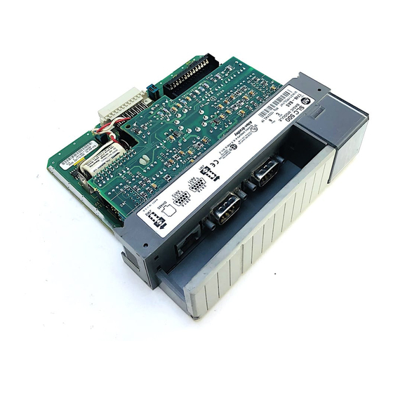
SLC 500 BASIC and BASIC-T Modules About the BASIC and BASIC-T Modules The BASIC module is a single-slot module that resides in a SLC 500 fixed or modular controller chassis. The BASIC-T module is a higher speed version of the BASIC module with identical hardware features, including two configurable serial ports for RS-232/423, RS-422, and RS-485 communication with I/O devices. -
Page 5: Before You Begin
SLC 500 BASIC and BASIC-T Modules Before You Begin Before you begin to install the BASIC module and BASIC-T module, you need to: • identify the communication ports, • locate the LED indicators, and • set the module jumpers. Identify the Communication Ports There are three communication ports on the front of the BASIC module and BASIC-T module. - Page 6 SLC 500 BASIC and BASIC-T Modules Figure 1 Communication Ports and LED Indicators BASIC FAULT BASIC BA LOW LEDs PR T1 LED1 PR T2 LED2 PRT1 PRT2 DH485 Color Status Indication Green The module is receiving power from the backplane and is executing BASIC code.
- Page 7 SLC 500 BASIC and BASIC-T Modules Set the Module Jumpers The BASIC module and BASIC-T module have four sets of jumpers that you need to set. Jumpers JW1 and JW2 configure ports PRT1 and PRT2. Jumper JW3 configures the type of optional memory module. Jumper JW4 configures the program port.
- Page 8 SLC 500 BASIC and BASIC-T Modules Settings other than those shown for each jumper may cause ATTENTION damage to the module. Module Jumper JW1 Use jumper JW1 to select one of the following configurations for port PRT1. • RS-232/423 • RS-422 •...
- Page 9 SLC 500 BASIC and BASIC-T Modules Module Jumper JW2 Use jumper JW2 to select one of the following configurations for port PRT2. • RS-232/423 • RS-422 • RS-485 Figure 4 Jumper JW2 Pin Assignments and Settings RS-232/423 (Shipped Configuration) Pin Assignments...
- Page 10 SLC 500 BASIC and BASIC-T Modules Figure 5 Jumper JW3 Pin Assignments and Settings Assignments 1 3 5 1747-M1 EEPROM 1747-M2 EEPROM 1747-M3 UVPROM 1771-DBMEM1 EEPROM 1771-DBMEM2 EEPROM (Shipped Configuration) 1747-M4 UVPROM This memory module is no longer available for sale from Rockwell Automation. Existing 1747-M3 and 1747-M4 memory modules are compatible with the 1746-BAS module and 1746-BAS-T module.
- Page 11 SLC 500 BASIC and BASIC-T Modules When DF1 protocol is selected for port PRT2, port DH485 is not IMPORTANT available for DH485 programming or run time operation. DF1 communication must be enabled through the BASIC program. Figure 6 Jumper JW4 Pin Assignments and Settings...
-
Page 12: Install The 1746-Bas Module And 1746-Bas-T Module
SLC 500 BASIC and BASIC-T Modules Install the 1746-BAS Module and 1746-BAS-T Module Your BASIC module or BASIC-T module may be installed in any open slot of an SLC 500 1746 I/O chassis except the first slot of the first chassis. The first slot is reserved for the controller or adapter module. -
Page 13: Wire The Prt1 And Prt2 Communication Ports
SLC 500 BASIC and BASIC-T Modules Wire the PRT1 and PRT2 Communication Ports Ports PRT1 and PRT2 can communicate to user devices through RS-232/423, RS-422, and RS-485 communication modes. The communication mode you select depends on the setting of jumpers JW1 and JW2. Refer to the MODE command in the BASIC Reference Manual, publication 1746-RM001, for the default programming port configuration information. -
Page 14: Module
SLC 500 BASIC and BASIC-T Modules Hardware Handshaking The module uses the following rules when hardware handshaking is enabled. The module: • does not transmit until CTS (Clear to Send) becomes active, and • examines DSR (Data Set Ready) following the receipt of a character. - Page 15 SLC 500 BASIC and BASIC-T Modules DCE - Data Communication Equipment Devices such as modems are Data Communication Equipment (DCE). The pinouts on these terminals are defined for ease of interfacing with DTE equipment. DCE 9 Signal Description Signal from DCE...
- Page 16 SLC 500 BASIC and BASIC-T Modules Figure 8 RS-232/423 Wiring Diagram - 1746-BAS Module or 1746-BAS-T Module to a Modem (Hardware Handshaking Enabled) BASIC DTE 9-Pin 25-Pin N.C. N.C. For DCE devices other than modems, connect the DSR of the IMPORTANT module with the DSR of the device.
- Page 17 SLC 500 BASIC and BASIC-T Modules Figure 10 RS-232/423 Wiring Diagram - 1746-BAS Module or 1746-BAS-T Module to Printer (Hardware Handshaking Enabled, Standard Printer Adapter Cable) BASIC DTE 9-Pin 25-Pin N.C. N.C. (1) The 1747-CP3 cable works in this application.
-
Page 18: Wire To The Dh485 Port
SLC 500 BASIC and BASIC-T Modules Wire to the DH485 Port Port DH485 can communicate to user devices through the DH485 communication mode. Use a 1747-C10 cable or 1747-C13 cable to connect the module to a link coupler interfaced with the DH485 network. -
Page 19: Apply Power To Your Basic Module And
SLC 500 BASIC and BASIC-T Modules Apply Power to your BASIC Module and BASIC-T Modules Once you have installed your BASIC module or BASIC-T module in your SLC 500 chassis, you are ready to apply power to your SLC 500 system and begin programming. -
Page 20: Battery Replacement, Handling, Storage, And
SLC 500 BASIC and BASIC-T Modules Battery Replacement, Handling, Storage, and Transportation (Cat. No. 1747-BA) Battery Replacement Your module provides back-up power for RAM through a replaceable lithium battery (cat. no. 1747-BA). This battery provides back-up for approximately five years. A BAT LOW indicator on the front of the module alerts you when the battery voltage has fallen below the replace battery threshold level. - Page 21 SLC 500 BASIC and BASIC-T Modules Figure 15 Battery Location Red WIre White WIre Lithium Battery 3. Unplug the battery connector. The module has a capacitor that provides 30 minutes of battery IMPORTANT back-up while the battery is disconnected. Data in RAM is not lost if the battery is replaced within 30 minutes.
- Page 22 SLC 500 BASIC and BASIC-T Modules Battery Storage Store the lithium batteries in a cool, dry environment, typically +20 °C to +25 °C (+68 °F to +77 °F) and 40% to 60% relative humidity. Battery Transportation One or Two Batteries You can ship up to two batteries together within the United States without restriction.
- Page 23 SLC 500 BASIC and BASIC-T Modules For disposal, batteries must be packaged and shipped in accordance with transportation regulations, to a proper disposal site. The U.S. Department of Transportation authorizes shipment of “Lithium batteries for disposal” by motor vehicle only in regulation 173.1015 of CFR 49 (effective January 5, 1983). For additional information contact: U.S.
-
Page 24: Specifications
SLC 500 BASIC and BASIC-T Modules Specifications BASIC and BASIC-T Modules Specifications Specification Value Power Supply Loading at 5V dc 0.150 A (module only) 0.150 A (module with link coupler) Power Supply Loading at 24V dc 0.070 A (module only) 0.125 A (module with link coupler) - Page 25 SLC 500 BASIC and BASIC-T Modules Operating Voltage and Current Requirement Component Operating Voltage Current Requirement Hand-Held Terminal 24V dc 0.105 A Data Table Access Module 24V dc 0.104 A Interface Converter 24V dc 0.060 A The module receives its power from the SLC backplane. The...
-
Page 26: Additional Resources
SLC 500 Instruction Set 1747-RM001 status file data, instruction set, and Reference Manual troubleshooting. To view and download pdfs, go to Literature Library at http://www.rockwellautomation.com/literature. To order printed copies, contact your Allen-Bradley Distributor or Rockwell Automation Sales Office. Publication 1746-IN009B-EN-P - August 2005... - Page 27 SLC 500 BASIC and BASIC-T Modules Publication 1746-IN009B-EN-P - August 2005...
- Page 28 Please contact your local Rockwell Automation representative for return States procedure. Rockwell Automation, Allen-Bradley, SLC 5/03, SLC 5/04, RSLogix 500, and TechConnect are trademarks of Rockwell Automation, Inc. Trademarks not belonging to Rockwell Automation are property of their respective companies.
Need help?
Do you have a question about the SLC 500 BASIC and is the answer not in the manual?
Questions and answers