Table of Contents
Advertisement
Advertisement
Table of Contents

Related Manuals for Allen-Bradley Rockwell Automation 1734-4IOL


Summary of Contents for Allen-Bradley Rockwell Automation 1734-4IOL
- Page 1 POINT I/O 4 Channel IO-Link Master Module User Manual (Catalog Number 1734-4IOL)
- Page 2 WARNING: Labels may be on or inside the equipment, for example, a drive or motor, to alert people that surfaces may reach dangerous temperatures. Allen-Bradley, Encompass, POINT I/O, Rockwell Automation, Rockwell Software, RSLogix 5000, Studio 5000, Studio 5000 Logix Designer, and TechConnect are trademarks of Rockwell Automation, Inc. CIP and EtherNet/IP are trademarks of ODVA, Inc.
-
Page 3: Table Of Contents
Table of Contents Table of Contents Preface Purpose of This Manual ..........7 Who Should Use This Manual . - Page 4 Table of Contents Register an IODD file ..........33 Add an IO-Link Device .
- Page 5 Table of Contents Troubleshooting Scenarios ........65 Second Data I/O connection rejected .
- Page 6 Table of Contents Notes: Rockwell Automation Publication 1734-UM020B-EN-E - August 2019...
-
Page 7: Purpose Of This Manual
Preface Purpose of This Manual This manual describes how to install, configure, and troubleshoot your POINT I/O™ IO-link Master module. The POINT I/O 4 Channel IO-Link Master module can only be used in EtherNet/IP™ systems. See EtherNet/IP publications in addition to this manual. When using the POINT I/O 4 Channel IO-Link Master module with a communication adapter, use this manual in conjunction with the user manual for the adapter you are using as shown in the following table. -
Page 8: Related Publications
Preface Related Publications See this table for a list of related POINT I/O products and documentation. The publications are available from https://literature.rockwellautomation.com/. For specification and safety certification information, see the installation instructions. Resource Description POINT I/O 4 Channel IO-Link Master POINT I/O 4 Channel IO-Link Master Installation Instructions, Provides installation information and wiring diagrams for the publication... -
Page 9: Overview
Chapter Introduction Overview The POINT I/O 4 Channel IO-Link Master module provides four channels that can be individually configured as IO-Link Master or as a standard digital I/O module. The IO-Link Master module can be configured to fit any IO-Link and/or discrete application. -
Page 10: Point I/O 4 Channel Io-Link Master - Io-Link Mode
Chapter 1 Introduction POINT I/O 4 Channel IO-Link Master - IO-Link Mode The POINT I/O 4 Channel IO-Link Master module can support IO-Link communications to IO-Link enabled devices in IO-Link Master mode. Chapter 4, Configure the POINT I/O 4 Channel IO-Link Master as IO-Link Master Using the Studio 5000 Add-on Profile. -
Page 11: Quick Start - Prepare The Module To Work On Ethernet/Ip
Introduction Chapter 1 You can also issue a wakeup command to the target device using a CIP™ message instruction. ATTENTION: When devices wake up from fallback to IO-link mode, response time for the devices may be impacted. Take necessary precautions to avoid unintended operation of machines or processes. - Page 12 Chapter 1 Introduction Notes: Rockwell Automation Publication 1734-UM020B-EN-E - August 2019...
-
Page 13: About This Chapter
Chapter Install the POINT I/O 4 Channel IO-Link Master Module About This Chapter Read this chapter for installation and wiring information including how to complete the following: Topic Page Install the Mounting Base Install the Module Install the Removable Terminal Block Remove a Mounting Base Wire the Modules Install the Mounting Base... -
Page 14: Install The Module
Chapter 2 Install the POINT I/O 4 Channel IO-Link Master Module 3. Press firmly to seat the mounting base on the DIN rail. The mounting base snaps into place. Be sure that the orange DIN rail locking screw is in the horizontal position and that it has engaged the DIN rail. -
Page 15: Install The Removable Terminal Block
Install the POINT I/O 4 Channel IO-Link Master Module Chapter 2 4. Press to secure. The module locks into place. 44013 Install the Removable A removable terminal block (RTB) is supplied with your wiring base assembly. To remove, pull up on the RTB handle. This allows the mounting base to be Terminal Block removed and replaced as necessary without removing any of the wiring. -
Page 16: Remove A Mounting Base
Chapter 2 Install the POINT I/O 4 Channel IO-Link Master Module Remove a Mounting Base To remove a mounting base, you must remove any installed module and the module installed in the base to the right. Remove the removable terminal block, if wired. - Page 17 Install the POINT I/O 4 Channel IO-Link Master Module Chapter 2 POINT I/O 4-Channel IO-Link Master Module Wiring – IO-Link Mode Ch 0 Ch 1 3-wire 3-wire Ch 2 Ch 3 Device Device Ch = IO-Link channel C = Common V = Voltage Device = IO-Link device (actuators, sensors) Channel...
- Page 18 Chapter 2 Install the POINT I/O 4 Channel IO-Link Master Module POINT I/O 4 Channel IO-Link Master Module Wiring – Standard Digital Output Mode Out 0 Out 1 3-wire 2-wire 2-wire 3-wire Out 2 Out 3 Out = Output channel C = Common V = Voltage Channel...
-
Page 19: Introduction
Chapter Add the POINT I/O 4 Channel IO-Link Master Module on an EtherNet/IP Network Introduction See the table for a list of where to find specific information in this chapter. Topic Page Install the POINT I/O 4 Channel IO-Link Master Add-On Profile Add a POINT I/O 4 Channel IO-Link Master Module to Studio 5000 IO-Link Tag Elements I/O Tags... - Page 20 Chapter 3 Add the POINT I/O 4 Channel IO-Link Master Module on an EtherNet/IP Network 1. In the installation package, double-click MPSetup.exe. The Welcome dialog box appears. Click Next. 2. Read and agree to the license and click Next. Rockwell Automation Publication 1734-UM020B-EN-E - August 2019...
- Page 21 Add the POINT I/O 4 Channel IO-Link Master Module on an EtherNet/IP Network Chapter 3 3. Select the option to install Studio 5000 Module Profile and click Next. 4. The Setup Wizard displays the profiles to be installed. Click Install to start the installation.
- Page 22 Chapter 3 Add the POINT I/O 4 Channel IO-Link Master Module on an EtherNet/IP Network 5. The Setup Wizard will begin to install the profiles. Rockwell Automation Publication 1734-UM020B-EN-E - August 2019...
-
Page 23: Add A Point I/O 4 Channel Io-Link Master Module To
Add the POINT I/O 4 Channel IO-Link Master Module on an EtherNet/IP Network Chapter 3 6. Follow the instructions on the next dialog boxes to complete the installation and configuration. When installation is complete the following dialog box appears. Click Finish. - Page 24 Chapter 3 Add the POINT I/O 4 Channel IO-Link Master Module on an EtherNet/IP Network 3. Under the Specialty, Digital, or Communications category, double-click the 1734-4IOL module. The General tab of the Add-on Profile appears. 4. Select the slot number from the Slot drop-down menu. On the General tab, you can give the module a Name that is also used in the name of the Tag elements that get created for the module, change the Electronic Keying for the module, and configure the module channel...
- Page 25 Add the POINT I/O 4 Channel IO-Link Master Module on an EtherNet/IP Network Chapter 3 On the Connection tab, you can change the Requested Packet Interval (RPI) (the default is 20 ms.), choose to inhibit the module, configure the controller so that a loss of connection to this module causes a major fault, and view module faults.
- Page 26 Chapter 3 Add the POINT I/O 4 Channel IO-Link Master Module on an EtherNet/IP Network On the Fault/Program tab, you can configure the state of the outputs during Program and Fault modes for channels that are configured as standard digital output or IO-Link. On the Configuration tab, you can change the Input Filter Time for each channel configured as standard digital input.
-
Page 27: Io-Link Tag Elements
Add the POINT I/O 4 Channel IO-Link Master Module on an EtherNet/IP Network Chapter 3 On the IO-Link tab, you can add and delete IO-Link devices to the channels of the Master Module configured as IO-Link, modify information for IO-Link channels, register IO-Link Device Description (IODD) files, and configure parameters for IO-Link devices. -
Page 28: I/O Tags
Chapter 3 Add the POINT I/O 4 Channel IO-Link Master Module on an EtherNet/IP Network names being created based on information from the IODD file. The Master Module translates and maps the information from IO-Link data types to Logix data types and also performs big-endian to little-endian (and little-endian to big-endian) swapping as required. -
Page 29: About This Chapter
Chapter Configure the POINT I/O 4 Channel IO-Link Master as IO-Link Master Using the Studio 5000 Add-on Profile About This Chapter In this chapter, you will learn how to configure the module as an IO-Link Master using the Studio 5000 Add-on Profile. This chapter covers the following topics: •... -
Page 30: Io-Link Device Integration Levels
Chapter 4 Configure the POINT I/O 4 Channel IO-Link Master as IO-Link Master Using the Studio 5000 Add-on Profile IO-Link Device Integration There are three levels of IO-Link device integration. Each level offers a different user experience. Levels • IODD Advanced This integration level is available for Rockwell Automation®... -
Page 31: Configure Channel Mode
Configure the POINT I/O 4 Channel IO-Link Master as IO-Link Master Using the Studio 5000 Add-on Profile Chapter 4 – In the Add-on Profile, you can configure only the Vendor ID, Device ID, Input and Output lengths, and Electronic keying information. –... -
Page 32: Configure Io-Link Devices
Chapter 4 Configure the POINT I/O 4 Channel IO-Link Master as IO-Link Master Using the Studio 5000 Add-on Profile For information about configuration of individual output states for IO-Link and standard digital output channels, refer to Parameters on the Fault/Program Action Tab page 53 Configure IO-Link Devices... -
Page 33: Register An Iodd File
Configure the POINT I/O 4 Channel IO-Link Master as IO-Link Master Using the Studio 5000 Add-on Profile Chapter 4 Register an IODD file An IO-Link Device Description (IODD) file is a set of multiple files including a file in XML format, which describes all parameters associated with the device. The IODD set also includes graphic image files of the device and vendor logo. -
Page 34: Add An Io-Link Device
Chapter 4 Configure the POINT I/O 4 Channel IO-Link Master as IO-Link Master Using the Studio 5000 Add-on Profile 3. Click Register IODD. The following dialog box appears. 4. Locate the IODD XML file, and then click Open. This returns you to the previous dialog box that shows the tree list view of registered IODD files. - Page 35 Configure the POINT I/O 4 Channel IO-Link Master as IO-Link Master Using the Studio 5000 Add-on Profile Chapter 4 2. Click the button in the Change Device column for the IO-Link channel. The following dialog box appears. 3. Select the IO-Link device from the tree. 4.
-
Page 36: Change Io-Link Channel Configuration
Chapter 4 Configure the POINT I/O 4 Channel IO-Link Master as IO-Link Master Using the Studio 5000 Add-on Profile Change IO-Link Channel You can change the Application Specific Name, Electronic Keying, Process Data Input configuration, and Device Discovery for an IO-Link channel while the Configuration project is in Offline mode. - Page 37 Configure the POINT I/O 4 Channel IO-Link Master as IO-Link Master Using the Studio 5000 Add-on Profile Chapter 4 d. Data Storage – Select how to store the data from the drop-down menu. When data storage is enabled, the device parameters are stored in the IO-link master.
- Page 38 Chapter 4 Configure the POINT I/O 4 Channel IO-Link Master as IO-Link Master Using the Studio 5000 Add-on Profile All devices that support data storage, including Rockwell Automation and Encompass™ Partner devices, default to Data Storage. When data storage is enabled for Rockwell Automation and Encompass partner devices, change data storage to ADC to view other tabs when offline.
- Page 39 Configure the POINT I/O 4 Channel IO-Link Master as IO-Link Master Using the Studio 5000 Add-on Profile Chapter 4 Device Discovery Dialog Parameter Description Status 6. Device on IO-Link Master. IODD file in Device only. There is a device connected to the master but no device configured for the channel in the project. The device has an IODD file (continued) that is not registered in the device catalog on the workstation.
-
Page 40: Configure Io-Link Device Parameters Using The Add-On Profile
Chapter 4 Configure the POINT I/O 4 Channel IO-Link Master as IO-Link Master Using the Studio 5000 Add-on Profile Device Discovery Dialog Parameter Description Status 19.Device on IO-Link Master. IODD File in Catalog only. There is a device connected to the master but no device configured for the channel in the project. The device has no IODD file but (continued) there is a file for the device registered in the device catalog on the workstation. - Page 41 Configure the POINT I/O 4 Channel IO-Link Master as IO-Link Master Using the Studio 5000 Add-on Profile Chapter 4 The Common tab provides general device information taken from the IODD file including the vendor logo and an image of the device. The Identification tab contains parameters with device identity information such as revisions and serial number.
- Page 42 Chapter 4 Configure the POINT I/O 4 Channel IO-Link Master as IO-Link Master Using the Studio 5000 Add-on Profile The Observation tab contains only I/O data, which can be used for debugging. The Parameter tab holds the most commonly used parameters to set up an IO-Link device.
- Page 43 Configure the POINT I/O 4 Channel IO-Link Master as IO-Link Master Using the Studio 5000 Add-on Profile Chapter 4 The Diagnosis tab contains parameters for trouble-shooting the IO-Link device such as temperature. 2. Select the tab where the parameter is located. Parameters are listed with their name, read-write attribute, value, and units (if available in the IODD file).
-
Page 44: Io-Link Device Parameter Behavior
Chapter 4 Configure the POINT I/O 4 Channel IO-Link Master as IO-Link Master Using the Studio 5000 Add-on Profile 3. Change the value of read-write parameters (through either edit controls or drop-down lists) and trigger write-only parameters by pressing the button for the parameter. -
Page 45: Add A Generic Io-Link Device
Configure the POINT I/O 4 Channel IO-Link Master as IO-Link Master Using the Studio 5000 Add-on Profile Chapter 4 • Correlation check is only performed on IO-Link devices with IODD Advanced integration. 1. From the IO-Link tab, on the working pane, click the Refresh button. If differences are detected, a dialog box appears and displays mismatch information per channel, including the parameters and the values present in the device and in the controller. - Page 46 Chapter 4 Configure the POINT I/O 4 Channel IO-Link Master as IO-Link Master Using the Studio 5000 Add-on Profile 1. In the channel tree, right-click on the IO-Link channel, and then select Change. Alternatively, you can click the Change button on the working pane. The following dialog box appears.
-
Page 47: Configure Io-Link Device Parameters Using Message Instructions
Configure the POINT I/O 4 Channel IO-Link Master as IO-Link Master Using the Studio 5000 Add-on Profile Chapter 4 c. Device ID – Enter the device ID of the IO-Link device. This field is disabled if Electronic Keying is Disabled d. - Page 48 Chapter 4 Configure the POINT I/O 4 Channel IO-Link Master as IO-Link Master Using the Studio 5000 Add-on Profile 1. In Studio 5000, go to Input/Output Instruction set and create a MSG instruction. 2. Create a controller tag for this instance of message instruction. 3.
- Page 49 Configure the POINT I/O 4 Channel IO-Link Master as IO-Link Master Using the Studio 5000 Add-on Profile Chapter 4 Message Configuration In this tab For this item Type or choose Configuration Source Length (bytes) one of the following according to the service code. 4B (read subindex) the length of the source element.
-
Page 50: Locate The Parameter Index Or Subindex Value In The Iodd File
IO-Link Data Description (IODD) XML file for that device or data sheet provided by the device vendor. Using the Distance Normalization parameter for an Allen-Bradley® sensor (model 45LMS-U8LGC3) as an example, refer to the following diagram to see where a specific parameter can be found on the device’s IODD file. -
Page 51: About This Chapter
Chapter Configure the POINT I/O 4 Channel IO-Link Master Module as Standard Digital Input or Output Using the Studio 5000 Add-on Profile About This Chapter In this chapter, you will learn how to do the following: • Configure the Module as Standard Digital Input Using the Configuration Tab •... - Page 52 Chapter 5 Configure the POINT I/O 4 Channel IO-Link Master Module as Standard Digital Input or Output Using the Studio 5000 Add-on Profile Parameters on the Configuration Tab Parameter Description Channel Displays channels that are used to set the channel’s configuration parameters.
-
Page 53: Chapter Summary And What's Next
Configure the POINT I/O 4 Channel IO-Link Master Module as Standard Digital Input or Output Using the Studio 5000 Add-on Profile Chapter 5 Parameters on the Fault/Program Action Tab Parameter Description Channel Displays the channels that are used to set the channel’s configuration parameters Mode Displays the mode that has been configured for each channel. - Page 54 Chapter 5 Configure the POINT I/O 4 Channel IO-Link Master Module as Standard Digital Input or Output Using the Studio 5000 Add-on Profile Notes: Rockwell Automation Publication 1734-UM020B-EN-E - August 2019...
-
Page 55: About This Appendix
Appendix Connected Data Mapping About This Appendix This appendix contains information to help you properly route the data to and from the IO-Link Master module. Communicate with the POINT I/O modules send (produce) and receive (consume) I/O data (messages). You map this data into the processor’s memory. Module The consumed and produced connection sizes may range from 0...32 bytes. - Page 56 Appendix A Connected Data Mapping Default Data Map for 1734-4IOL – Configuration Assembly Instance 100 Message size: 46 Bytes Consumed Byte Bit 7 Bit 6 Bit 5 Bit 4 Bit 3 Bit 2 Bit 1 Bit 0 IO-Link channel 2 Process Input Size IO-Link channel 3 Process Output Size IO-Link channel 3 Process Input Size Channel 0 Fault Mode...
- Page 57 Connected Data Mapping Appendix A Consumed sizes can be in the range of 0...32. Output data for each channel always begin on a 32-bit boundary, and is enforced by software using the data description for the channel. Default Data Map for 1734-4IOL – Produced Assembly Instance 102 Message size: 0...132 Bytes Consumed Byte Bit 7...
- Page 58 Appendix A Connected Data Mapping Notes: Rockwell Automation Publication 1734-UM020B-EN-E - August 2019...
-
Page 59: About This Appendix
Appendix Supported IO-Link Master Events About This Appendix This appendix provides information about events that are defined in the IO Link master stack. This appendix also shows where the most recent events are viewable in the Controller Tags view of the Studio 5000 program. IO-Link Master IO-Link events can be accessed through Explicit Messaging by querying the Events attribute of an IO-Link Module object. -
Page 60: Io-Link Master Event Codes
Appendix B Supported IO-Link Master Events IO-Link Master Event Codes The IO-Link Interface and System Specification document provides an enumeration and definition of IO-Link defined events. Unique event conditions can also be defined by the IO-Link device or the IO-Link master stack. Events defined by the stack are shown in the table below. -
Page 61: Event Qualifier
Supported IO-Link Master Events Appendix B Event Qualifier The Event Qualifier provides details about the type event, as shown in the table below. Event Qualifier Bit(s) Name Definition 0...2 Source These bits indicate the source of an Event: 0: Unknown 1: Physical Layer 2: Data Layer 3: Application Layer... - Page 62 Appendix B Supported IO-Link Master Events Notes: Rockwell Automation Publication 1734-UM020B-EN-E - August 2019...
-
Page 63: About This Appendix
Appendix Troubleshooting About This Appendix This appendix provides information about module diagnostics, and about troubleshooting with the following indicators: • Module status • Network status • Standard digital I/O status (ON/OFF/fault or diagnostic) • IO-Link status In addition, the following troubleshooting scenarios are provided: •... -
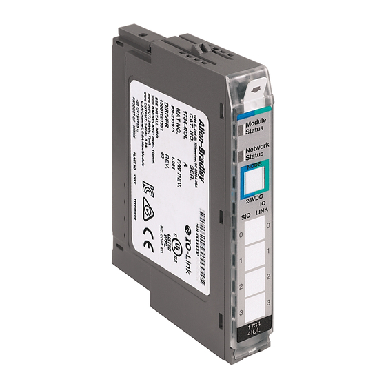
Page 64: Interpret Led Indicators
Appendix C Troubleshooting Interpret LED Indicators See the following diagram and table for information on how to interpret the status indicators. POINT I/O 4-Channel IO-Link Master Module – 1734-4IOL Module status Module Status Network status Network Status NODE: NODE: 24V DC LINK Status of Standard Digital I/O 0 Status of IO-Link 0... - Page 65 Troubleshooting Appendix C Troubleshooting Scenarios The following are scenarios you may encounter while using the modules. Second Data I/O connection rejected The 1734-4IOL module does not support a Listen-Only or Input-Only connection. A connection attempt from a second Logix controller will be rejected.
- Page 66 Appendix C Troubleshooting The ChxMostRecentEvent.EventSequenceCount is an unsigned value The ChxMostRecentEvent.EventSequenceCount is a count value assigned to each event. The value increments for each received event. Range of values is 1...255; a value of zero is not valid and can indicate that no event is present. Because this is an unsigned number the count values from 128 through 255 will appear as negative numbers in the Logix Designer software.
- Page 68 Rockwell Automation Support Rockwell Automation provides technical information on the Web to assist you in using its products. At http://www.rockwellautomation.com/support/, you can find technical manuals, a knowledge base of FAQs, technical and application notes, sample code and links to software service packs, and a MySupport feature that you can customize to make the best use of these tools.
Need help?
Do you have a question about the Rockwell Automation 1734-4IOL and is the answer not in the manual?
Questions and answers