Table of Contents
Advertisement
Advertisement
Table of Contents

Related Manuals for Allen-Bradley POINT I/O 1734-232ASC


Summary of Contents for Allen-Bradley POINT I/O 1734-232ASC
- Page 1 POINT I/O RS-232 ASCII Module 1734-232ASC User Manual Spare Allen-Bradley Parts...
- Page 2 In no event will Allen-Bradley be responsible or liable for indirect or consequential damage resulting from the use or application of these products.
- Page 3 1. Go to http://www.ab.com 2. Click on Product Support (http://support.rockwellautomation.com) Your Questions or Comments on this Manual If you find a problem with this manual, please notify us of it on the enclosed How Are We Doing form. Spare Allen-Bradley Parts...
- Page 5 Electronic Data Sheet (EDS) files. We assume you know how to do this in this manual. If you do not, refer to your software user manuals or online help before attempting to use this module. Spare Allen-Bradley Parts Publication 1734-UM009A-EN-P - June 2002...
- Page 6 Preface Related Products and The following table lists related POINT I/O products and documentation. Documentation Catalog Number Description Related Publications Communication DeviceNet Adapter (Cat. No. 1734-ADN) Installation Instructions 1734-IN007 Adapter Communication DeviceNet Interface (Cat. No. 1734-PDN) Installation Instructions 1734-IN057 Interface 1734D Series 1734D Series 24V dc 8 In/8 Out Combo Module (Cat.
- Page 7 24V dc, 120V ac, and 240V ac 2 Relay Sink/Source Output Module (Cat. No. Installation Instructions 1734-IN055 1734-OW2) Field Power Field Power Distributor (Cat. No. 1734-FPD) Installation Instructions 1734-IN059 Distributor Expansion Power 24V dc Expansion Power Supply (Cat. No. 1734-EP24DC) Installation Instructions 1734-IN058 Supply Spare Allen-Bradley Parts Publication 1734-UM009A-EN-P - June 2002...
- Page 8 Preface Notes: Publication 1734-UM009A-EN-P - June 2002...
-
Page 9: Table Of Contents
Explicit Messages to Receive the Serial Data String ..2-20 Status Byte Description ......2-20 Spare Allen-Bradley Parts Publication 1734-UM009A-EN-P - June 2002... - Page 10 Table of Contents Transmitting Serial Data to the ASCII Device ... 2-21 Setting Up the Transmit Character Buffer Length ..2-22 Setting Up and Using the Transmit Delimiter..2-22 Transmit String Data Assemblies .
-
Page 11: Installing The Rs-232 Ascii Module
Terminal Block (RTB) with field side power applied, an electrical arc can occur. This could cause an explosion in hazardous location installations. Be sure that power is removed or the area is nonhazardous before proceeding. Spare Allen-Bradley Parts Publication 1734-UM009A-EN-P - June 2002... - Page 12 Installing the RS-232 ASCII Module 1. Position the mounting base/wiring base assembly vertically above the installed units (adapter, power supply or existing module). 2. Slide the mounting base down allowing the interlocking side pieces to engage the adjacent module or adapter. Slide-in Writable Label Module Locking Mechanism Insertable I/O Module...
-
Page 13: Installing An I/O Module
3. Insert the module straight down into the mounting base and press to secure. The module will lock into place. Spare Allen-Bradley Parts Publication 1734-UM009A-EN-P - June 2002... -
Page 14: Installing The Removable Terminal Block
Installing the RS-232 ASCII Module Installing the Removable A removable terminal block is supplied with your mounting base assembly. To remove, pull up on the RTB handle. This allows the base Terminal Block to be removed and replaced as necessary without removing any of the wiring. -
Page 15: Removing A Mounting Base
5. Use a small bladed screwdriver to rotate the orange DIN rail locking screw on the mounting base to a vertical position. This releases the locking mechanism. 6. Then lift the mounting base straight up to remove. Spare Allen-Bradley Parts Publication 1734-UM009A-EN-P - June 2002... -
Page 16: Wiring The 1734-232Asc Module
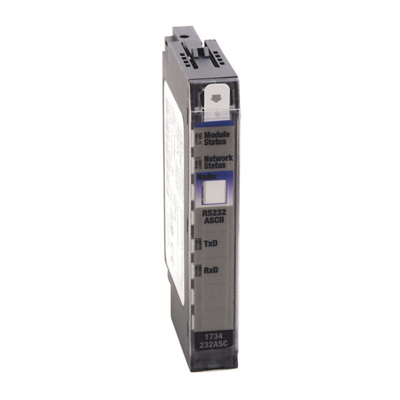
Installing the RS-232 ASCII Module Wiring the Shielded Cable: The 1734-232ASC module 1734-232ASC Module requires shielded cable to help reduce the Module Module Status Status effects of electrical noise coupling. Ground Network Status Network each shield at one end only. A shield grounded Status NODE: at both ends forms a ground loop, which can... -
Page 17: Cable Pinouts For Standard Db Connectors
In many configuration tools, this will unmap the data in your scanner’s scan list. They must be remapped in order to process the data in your PLC or PC software. These values are displayed in the Parameter Object, Class 15 (F Spare Allen-Bradley Parts Publication 1734-UM009A-EN-P - June 2002... -
Page 18: How To Read Serial Device Input Data From The 1734-232Asc
Installing the RS-232 ASCII Module 5. The 1734-232ASC produces and consumes the number of ASCII characters selected plus four. These produce and consume sizes are presented for your information in parameters 13 and 23, respectively. Make sure that you set up your scanner to the correct sizes using this data. -
Page 19: How To Write Serial Output Data To The 1734-232Asc
Table 1.3 Default Transmit Data Assembly Format (Default Mode) Byte 1 Byte 2 Byte 3 Byte 4 Byte 5-23 Byte 24 Reserved TX Transaction ID Reserved Length ASCII Data <CR> Byte (Terminator) Spare Allen-Bradley Parts Publication 1734-UM009A-EN-P - June 2002... -
Page 20: Setting Up Devicenet Communications
1-10 Installing the RS-232 ASCII Module Setting Up DeviceNet The 1734-232ASC module supports 4 modes of data transfer of the serial buffer: Communications • Polled I/O • Change of State I/O • Cyclic I/O • Explicit Message Polled I/O The 1734-232ASC module monitors the transaction ID for a change in the transaction ID. -
Page 21: Cyclic And Change Of State I/O
See Table 2.3 for receive and transmit sizes. The input and output sizes are computed from the transmit size and the receive sizes plus selected options. These sizes are defined in the parameter object of your device. Spare Allen-Bradley Parts Publication 1734-UM009A-EN-P - June 2002... -
Page 22: Setting Up The Connection Timer (Epr)
1-12 Installing the RS-232 ASCII Module The transmit and receive sizes of the I/O connection are automatically computed for you by the 1734-232ASC module. You must set the maximum RX and TX sizes first and then choose apply. Upload the data to the 1734-232ASC by clicking Upload. -
Page 23: Operating Mode Selections
I/O messaging. See page 2-24 for details. These actions take place with either a Poll command or an explicit message that writes to the consume assembly object or the serial port object. Spare Allen-Bradley Parts Publication 1734-UM009A-EN-P - June 2002... -
Page 24: Produce Immediate Vs. Master/Slave Handshake Option
1-14 Installing the RS-232 ASCII Module Produce Immediate vs. Master/Slave Handshake Option This option defines when the 1734-232ASC module sends new data to the DeviceNet Master (produces new data on DeviceNet). In Produce Immediate mode (default), the 1734-232ASC module sends its most current serial port data to the DeviceNet Master in response to each Poll command or explicit message, or in response to a COS or Cyclic event. -
Page 25: Configuring Your Rs-232 Ascii Module
Default values are 24 bytes. If you are not familiar with these terms, see the DeviceNet Specification for definitions (online: www.odva.org). The 1734-232ASC module is not compatible with the ATTENTION 1734-APB PROFIBUS adapter. Spare Allen-Bradley Parts Publication 1734-UM009A-EN-P - June 2002... -
Page 26: Configuration Overview
Configuring Your RS-232 ASCII Module Configuration Overview You must use the RSNetworx for DeviceNet software to configure your module. You can configure the module while it is: • online • offline This chapter shows configuration in the online mode. Configuration screens appear similar in both modes. - Page 27 I/O connections with the adapter, the attempt to use Auto Start Mode is rejected. Also, when the adapter is configuring itself in Auto Start Mode, no other device can establish I/O connections to the adapter. Spare Allen-Bradley Parts Publication 1734-UM009A-EN-P - June 2002...
-
Page 28: Adding The Rs-232 Ascii Module To Your Network
Configuring Your RS-232 ASCII Module Adding the RS-232 ASCII Module to Your Network Follow these steps: 1. Start the RSNetworx for DeviceNet software. 2. Add the communication device as shown below. (In this case, the chosen device was a 1734-ADN DeviceNet adapter.) 1. -
Page 29: Adding I/O Modules To Your Network
The out-of-the-box node setting for 1734 modules is 63. You can change the setting by using the node commissioning tool. The node commissioning tool is available either online or offline. 2. Double-click on the module to change the node address. Spare Allen-Bradley Parts Publication 1734-UM009A-EN-P - June 2002... -
Page 30: Setting The Rs-232 Ascii Module's Parameters
Configuring Your RS-232 ASCII Module Setting the RS-232 ASCII After adding the module to the network, you must configure the module for use. Module’s Parameters This chapter shows configuration in the online IMPORTANT mode. Changes set in this mode take effect when you download to the individual module. - Page 31 When you have finished configuring your parameters, download to your module by clicking on the Download to Device button. You can download each change as you make it using “Single,” or download all your changes using “All.” Spare Allen-Bradley Parts Publication 1734-UM009A-EN-P - June 2002...
-
Page 32: Checking I/O Status And Viewing The Eds File
Configuring Your RS-232 ASCII Module Checking I/O Status and You can view the I/O data setup, and the EDS file by clicking on the appropriate tab. Viewing the EDS File Click on the I/O Defaults tab to display the default characteristics for this module. -
Page 33: Configuration Assembly
DeviceNet Handshake Mode ASCII Max Number of Transmit Characters ASCII Transmit End Delimiter Mode ASCII Transmit End Delimiter Character ASCII Consume String Data Type ASCII Transmit Swap Mode DeviceNet Record Header Mode Spare Allen-Bradley Parts Publication 1734-UM009A-EN-P - June 2002... -
Page 34: Parameter List
2-10 Configuring Your RS-232 ASCII Module Parameter List Use this table for information on configuring your 1734-232ASC module parameters. Table 2.3 Parameter List Parameter Parameter Access Description Parameter Choices Default Default Data Type Instance Setting Value Serial Port Parameters Serial Character Get/Set Defines the number 0 = 7N2... - Page 35 0-128 bytes long STRING Receive Data Size Number of 0-128 USINT characters in the Receive data buffer Receive transaction Get/Set The Receive 0-255 USINT transaction ID sent from the master Spare Allen-Bradley Parts Publication 1734-UM009A-EN-P - June 2002...
- Page 36 2-12 Configuring Your RS-232 ASCII Module Table 2.3 Parameter List Parameter Parameter Access Description Parameter Choices Default Default Data Type Instance Setting Value Serial Port Transmit to ASCII Device Max Number of Get/Set Maximum number of 1-128 20 chars USINT Transmit Chars characters the 1734-232ASC...
- Page 37 1 = Disable baud rate of existing devices on a network. Changes to this attribute take effect after the next powerup. If ’Enabled’, the Baud Rate Attribute cannot be set. Spare Allen-Bradley Parts Publication 1734-UM009A-EN-P - June 2002...
- Page 38 2-14 Configuring Your RS-232 ASCII Module Table 2.3 Parameter List Parameter Parameter Access Description Parameter Choices Default Default Data Type Instance Setting Value Sequential Sequential 0 = Do Nothing Do Nothing USINT AutoAddress AutoAddress will 1 = Sequential reassign the node Address address of every module to the right.
-
Page 39: Point I/O Parameters
This value can be set and retrieved by using the standard set and get services on class 15 (F instance 3, attribute 1. Spare Allen-Bradley Parts Publication 1734-UM009A-EN-P - June 2002... -
Page 40: Setting Up And Using Pad Mode
2-16 Configuring Your RS-232 ASCII Module Setting Up and Using Pad Mode Pad Mode operation adds extra characters to the end of its received data string (after the delimiter character). These characters are added from the external I/O device before sending the string to the DeviceNet scanner (master) as an I/O response. -
Page 41: Setting Up And Using The Swap Bytes Mode
Maximum Number of Receive Characters Parameter Rules for Usage • Swap Bytes Mode is set for transmit and receive independently. • The byte swapping works best if the max RX and TX lengths are multiples of the byte-swap size. Spare Allen-Bradley Parts Publication 1734-UM009A-EN-P - June 2002... -
Page 42: Setting Up And Using Delimiter Operation
2-18 Configuring Your RS-232 ASCII Module Setting Up and Using Delimiter Operation When receiving data strings from your serial device, the 1734-232ASC module can take advantage of both Start and Stop (End) delimiters. The Start Delimiter is the start-of-string indicator and the End Delimiter is the end-of-string indicator. -
Page 43: Setting Up The Scanner I/O Receive Size
You must set your scanner’s RX (receive) value to IMPORTANT this number of bytes. You must upload this data from the 1734-232ASC IMPORTANT module to view current information or put your RSNetWorx for DeviceNet into Monitor Mode. Spare Allen-Bradley Parts Publication 1734-UM009A-EN-P - June 2002... -
Page 44: Explicit Messages To Receive The Serial Data String
2-20 Configuring Your RS-232 ASCII Module Explicit Messages to Receive the Serial Data String Parameters 14, 15, and 16 contain the status of the most recent incoming serial data string. You can use the data to read your device’s ASCII data via the explicit messaging technique. Parameter 14 holds the most recent received data. -
Page 45: Transmitting Serial Data To The Ascii Device
• the defined End-of-String Terminator character is detected and active. When either of these events occur, the 1734-232ASC module stores the DeviceNet string data into its internal buffer and then transmits it out its serial port. Spare Allen-Bradley Parts Publication 1734-UM009A-EN-P - June 2002... -
Page 46: Setting Up The Transmit Character Buffer Length
2-22 Configuring Your RS-232 ASCII Module Setting Up the Transmit Character Buffer Length The Transmit Character Buffer Length is the number of characters that the 1734-232ASC module can receive in its transmit buffer from the DeviceNet network. This size contributes to the I/O’s consume size. This size can be found in the Parameter object. -
Page 47: Transmit String Data Assemblies
Byte X+1 (Max = 132) Next RX ID Byte Transaction ID Byte Length (LSB) Length (MSB) ASCII Data End of String (Handshake Mode (max 128 bytes) Delimiter or Last Only) Data Byte Spare Allen-Bradley Parts Publication 1734-UM009A-EN-P - June 2002... -
Page 48: Transmit Handshake Vs. Transmit Immediate Mode
2-24 Configuring Your RS-232 ASCII Module Transmit Handshake vs. Transmit Immediate Mode This options defines when the 1734-232ASC module transmits data out is serial port. Transmit Handshake mode is used primarily in Polled I/O to prevent the 1734-232ASC module from repeatedly sending its data buffer to the serial device each time an I/O command is received. - Page 49 If the data string represents a command message to your target device, these actions could result in unintended misoperationg of your device or system. Spare Allen-Bradley Parts Publication 1734-UM009A-EN-P - June 2002...
-
Page 50: Transmitting Serial Data
2-26 Configuring Your RS-232 ASCII Module Transmitting Serial Data The length of the string sent determines the use of a delimiter in transmitting data to a serial device from the 1734-232ASC module. • If the string length is zero (as dynamically defined by the third and fourth bytes in the message header), or if the data type is Array: The 1734-232ASC module receives data sent from the DeviceNet... -
Page 51: Produce Immediate Vs. Master/Slave Handshake Mode
Byte 5-X Byte X+1 (Max = 132) Next RX ID Byte Transaction ID Byte Reserved Length ASCII Data End of String (Handshake Mode (max 128 bytes) Delimiter or Last Only) Data Byte Spare Allen-Bradley Parts Publication 1734-UM009A-EN-P - June 2002... -
Page 52: Explicit Messages To Transmit Serial Data String
2-28 Configuring Your RS-232 ASCII Module The master monitors the new data flag and when the master is ready to receive new serial data, it sets a new number in the new RX ID byte of the I/O message. Note that this applies only to data being sent from the 1734-232ASC module to the master. -
Page 53: Using The Indicators For Troubleshooting
Green Device operating normally. Flashing Green Device needs commissioning due to configuration missing, incomplete or incorrect. Flashing Red Recoverable fault. Unrecoverable fault may require device replacement. Flashing Device is in self-test. Red/Green Spare Allen-Bradley Parts Publication 1734-UM009A-EN-P - June 2002... - Page 54 Diagnostics Table 3.2 Network Status Indicators Indication Probable Cause Network Status Device is not on-line. - Device has not completed dup_MAC_id test. - Device not powered - check module status indicator. Flashing Green Device is on-line but is not allocated to a master. Green Device on-line and has connections in the established state.
-
Page 55: Specifications For The 1734-232Asc Module
Pad Mode Pad mode disabled, enabled Pad Character ASCII character Receive Swap Mode Disabled, 16-bit, 24-bit, 32-bit swap DeviceNet Handshake Mode Master/slave handshake, produce immediate Produce Assembly Size 4-132 Serial Data 0-128 bytes Spare Allen-Bradley Parts Publication 1734-UM009A-EN-P - June 2002... - Page 56 Specifications Specifications - 1734-232ASC RS-232 ASCII Module (Continued) Receive Transaction ID 0-255 Serial Port Transmit to ASCII Device Max Number of Transmit Chars 1-128 Transmit End Delimiter Mode No, exclude, include end delimiter Transmit End Delimiter Character ASCII character Consume on DeviceNet from Master Consume String Data Type Array, short_string, string Transmit Swap Mode...
- Page 57 Use this conductor category information for planning conductor routing as described in publication 1770-4.1, “Industrial Automation Wiring and Grounding Guidelines.” See the Product Certification link at www.ab.com for Declaration of Conformity, Certificates, and other certification details. Spare Allen-Bradley Parts Publication 1734-UM009A-EN-P - June 2002...
- Page 58 Specifications Notes: Publication 1734-UM009A-EN-P - June 2002...
-
Page 59: Appendix B About These Examples
The ASCII devices are connected to the 1734-232ASC module via a 3-wire communications cable. The RX and TX designators are referenced with respect to the 1734-232ASC module. SG is signal ground. Table B.1 RS232 Connector Signals Pin Signal Signal Pin Spare Allen-Bradley Parts Publication 1734-UM009A-EN-P - June 2002... -
Page 60: Eds Configuration
Using the 1734-232ASC Module with the ControlLogix System Application Examples EDS Configuration You can configure the 1734-232ASC module through the EDS file using RSNetWorx for DeviceNet. For this example, the following configuration was used: Table B.2 Application Example Configuration Parameter Value Maximum receive characters Receive data type... -
Page 61: Devicenet Data Details
When this happens, a new data buffer is available for storage. Read the length of the data from byte 4 and copy that amount of bytes from the data buffer starting at byte 5 into a file. Spare Allen-Bradley Parts Publication 1734-UM009A-EN-P - June 2002... -
Page 62: Reading Data From The 1734-232Asc Module Into Controllogix
Using the 1734-232ASC Module with the ControlLogix System Application Examples Reading Data from the 1734-232ASC Module into ControlLogix For this example, the advanced mapping feature in RSNetWorx for DeviceNet was used to separate the header bytes into their own data locations. - Page 63 If data is being received quite often, we recommend storing the receive data into some kind of large rotary buffer so as not to overwrite an older packet before it is decoded. Spare Allen-Bradley Parts Publication 1734-UM009A-EN-P - June 2002...
-
Page 64: Transmitting Data From Controllogix Through The 1734-232Asc Module
Using the 1734-232ASC Module with the ControlLogix System Application Examples Transmitting Data from ControlLogix Through the 1734-232ASC Module For this example, the advanced mapping feature in RSNetWorx for DeviceNet was used to separate the header bytes into their own data locations. - Page 65 Local:1:O.Data[4] and a constant length of 9 is in Local:1:O.Data[3]. Under normal conditions, the transmit data and length would be loaded by the ladder program prior to incrementing the transaction ID. Spare Allen-Bradley Parts Publication 1734-UM009A-EN-P - June 2002...
- Page 66 Using the 1734-232ASC Module with the ControlLogix System Application Examples Notes: Publication 1734-UM009A-EN-P - June 2002...
- Page 67 Configuration overview Installing, I/O module configuration software Installing, mounting base 1-12 Connection timer, setting up Installing, removable terminal block ControlLogix examples Installing, serial network 1-11 Cyclic I/O Installing, wiring base assembly keyswitch position Spare Allen-Bradley Parts Publication 1734-UM009A-EN-P - June 2002...
- Page 68 Index Mode, auto start Reading, serial device input data 2-24 Mode, data only Receive character buffer length, receive 1-14, 2-27 2-15 Mode, handshake 1-14, 2-27 Mode, immediate Receive characters parameter, rules for 1-14 2-17 Mode, no pad usage 1-14 Mode, pad Receive serial data string, explicit 2-16 2-20...
- Page 69 Transmit character buffer length, setting 2-22 2-22 Transmit delimiter, setting up Transmit serial data string, explicit 2-28 messages 2-23 Transmit, string data assemblies 2-17 Transmit, swap bytes 2-21, 2-26 Transmitting, serial data 2-20 TX buffer overflow Spare Allen-Bradley Parts Publication 1734-UM009A-EN-P - June 2002...
- Page 70 Index Notes: Publication 1734-UM009A-EN-P - June 2002...
- Page 71 ___Yes, please call me ___Yes, please email me at __________________________ ___Yes, please contact me via ________________________ Return this form to: Rockwell Automation Technical Communications, 1 Allen-Bradley Dr., Mayfield Hts., OH 44124-9705 Spare Allen-Bradley Parts Phone: 440-646-3176 Fax: 440-646-3525 Email: RADocumentComments@ra.rockwell.com Publication ICCG-5.21- February 2002...
- Page 72 PLEASE FASTEN HERE (DO NOT STAPLE) Other Comments PLEASE FOLD HERE NO POSTAGE NECESSARY IF MAILED IN THE UNITED STATES BUSINESS REPLY MAIL FIRST-CLASS MAIL PERMIT NO. 18235 CLEVELAND OH POSTAGE WILL BE PAID BY THE ADDRESSEE 1 ALLEN-BRADLEY DR MAYFIELD HEIGHTS OH 44124-9705...
- Page 73 Spare Allen-Bradley Parts...
- Page 74 Publication 1734-UM009A-EN-P - June 2002 PN 957626-53 Copyright © 2002 Rockwell Automation. All rights reserved. Printed in the U.S.A.
Need help?
Do you have a question about the POINT I/O 1734-232ASC and is the answer not in the manual?
Questions and answers