Table of Contents
Advertisement
Quick Links
UM_2301_PL88_2302_002220
User manual for MERUS™ evaluation boards
EVAL_AUDIO_MA12070_B and EVAL_AUDIO_MA12070P_B
About this document
Scope and purpose
This user manual describes the EVAL_AUDIO_MA120xxx_B evaluation and demonstration board for
and
MA12070P
proprietary multilevel amplifiers.
Intended audience
Audio amplifier design engineers
Attention:
Please read through this user manual before operating the board. When powering up the
board make sure to follow the instructions in the "Start sequence" section.
Attention:
Please observe proper electrostatic discharge (ESD) handling procedures. Failure to do so
may result in damage to components on the board.
User Manual
www.infineon.com/audiosolutions
Please read the Important Notice and Warnings at the end of this document
page 1 of 23
MA12070
V 1.0
2023-03-02
Advertisement
Table of Contents

Related Manuals for Infineon MERUS EVAL AUDIO MA12070 B


Summary of Contents for Infineon MERUS EVAL AUDIO MA12070 B
-
Page 1: About This Document
Please observe proper electrostatic discharge (ESD) handling procedures. Failure to do so may result in damage to components on the board. User Manual Please read the Important Notice and Warnings at the end of this document V 1.0 www.infineon.com/audiosolutions page 1 of 23 2023-03-02... -
Page 2: Table Of Contents
User manual for MERUS™ evaluation boards EVAL_AUDIO_MA12070_B and EVAL_AUDIO_MA12070P_B Table of contents Table of contents About this document ........................1 Table of contents ..........................2 Overview ..........................3 Board features and audio performance ....................3 EVK device type ............................4 Setup guide ........................... -
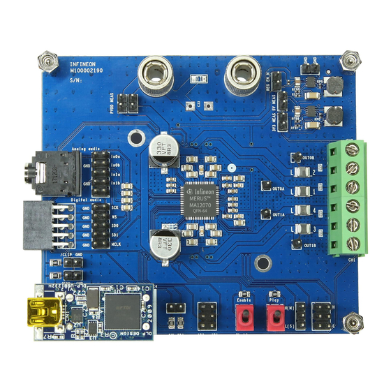
Page 3: Overview
User manual for MERUS™ evaluation boards EVAL_AUDIO_MA12070_B and EVAL_AUDIO_MA12070P_B Overview Overview This is an evaluation and demonstration board for MERUS™ audio MA12070 and MA12070P amplifiers. It contains a variety of digital/analog input, output and setup/selection features. It also contains two onboard power supply generators (5 V and 3.3 V buck-converted) so only one external power supply (PVDD) is necessary. -
Page 4: Evk Device Type
User manual for MERUS™ evaluation boards EVAL_AUDIO_MA12070_B and EVAL_AUDIO_MA12070P_B Overview EVK device type The type of device (MA12070 or MA12070P) on the EVK is printed on the top of the board and is also stated on the serial number label on the bottom side of the EVK PCB. User Manual 4 of 23 V 1.0... -
Page 5: Setup Guide
User manual for MERUS™ evaluation boards EVAL_AUDIO_MA12070_B and EVAL_AUDIO_MA12070P_B Setup guide Setup guide Equipment required for operating and evaluating: Single power supply for PVDD • Analog audio source or signal generator with line-level output (MA12070) • Digital I S audio source (MA12070P) •... - Page 6 User manual for MERUS™ evaluation boards EVAL_AUDIO_MA12070_B and EVAL_AUDIO_MA12070P_B Setup guide Table 1 EVK headers and connectors Name Schem. ref. Description Comment MSEL0 JMSEL Selects in conjunction with MSEL1 Default: 2CH BTL. the output configuration (see Table Jumpered high (H). MSEL1 JMSEL Selects in conjunction with MSEL0...
- Page 7 User manual for MERUS™ evaluation boards EVAL_AUDIO_MA12070_B and EVAL_AUDIO_MA12070P_B Setup guide Name Schem. ref. Description Comment ANALOG AUDIO Balanced analog audio input Jack input = All connector. Also selects “JACK” Jumpered input Balanced input = Use Note: See Section 2.2 for setting up pins for balanced analog audio input Note: Should NOT be...
-
Page 8: Notes To Digital Audio And Analog Audio Headers
User manual for MERUS™ evaluation boards EVAL_AUDIO_MA12070_B and EVAL_AUDIO_MA12070P_B Setup guide Table 3 C address decoding (ADD) C device address 7-bit I C address 0x20 0b0100000 0x21 0b0100010 0x22 0b0100001 Notes to digital audio and analog audio headers When using the “digital audio header” for digital I S input stream (MA12070P), the connection scheme should appear as follows (from top to bottom, left side of the header): SCK: Word clock;... -
Page 9: Operating The Demonstration Board
User manual for MERUS™ evaluation boards EVAL_AUDIO_MA12070_B and EVAL_AUDIO_MA12070P_B Operating the demonstration board Operating the demonstration board Recommended operating conditions Table 4 Recommended operating conditions Minimum Nominal Maximum Unit PVDD (MA12070/MA12070P) Output peak current (MA12070/MA12070P) Toggle switches The board has two toggle switches. The toggle switches have the following functions: Table 5 Switch function Function... -
Page 10: Start Sequence
User manual for MERUS™ evaluation boards EVAL_AUDIO_MA12070_B and EVAL_AUDIO_MA12070P_B Operating the demonstration board Figure 2 GUI main window By default the MA12xx/P will automatically select the relevant power mode (PM1, PM2 or PM3), based on detection of audio level during operation. The selected power mode is indicated by a blue color in the power mode indicator. -
Page 11: Digital (I 2 S) Input Configuration (Ma12070P Devices)
User manual for MERUS™ evaluation boards EVAL_AUDIO_MA12070_B and EVAL_AUDIO_MA12070P_B Operating the demonstration board 6. Start the GUI software by running the executable file to monitor device status. 7. Make sure the GUI indicates a valid device ID and connection status (bottom right GUI). 8. - Page 12 User manual for MERUS™ evaluation boards EVAL_AUDIO_MA12070_B and EVAL_AUDIO_MA12070P_B Operating the demonstration board Figure 3 Digital audio processing window (top) and I S setup window (bottom) User Manual 12 of 23 V 1.0 2023-03-02...
-
Page 13: Measurement Methods
User manual for MERUS™ evaluation boards EVAL_AUDIO_MA12070_B and EVAL_AUDIO_MA12070P_B Measurement methods Measurement methods Setting up a reliable measurement configuration for MA12070 or MA12070P takes a little bit more effort than linear amplifiers and even “regular” switching amplifiers. This is mainly because MA12070 and MA12070P are filterless amplifiers, which means they do not require an external (usually expensive and bulky) LC filter to remove switching residuals. - Page 14 User manual for MERUS™ evaluation boards EVAL_AUDIO_MA12070_B and EVAL_AUDIO_MA12070P_B Measurement methods Figure 4 Recommended measurement setup for analog input (MA12070) User Manual 14 of 23 V 1.0 2023-03-02...
-
Page 15: Evk Schematic
User manual for MERUS™ evaluation boards EVAL_AUDIO_MA12070_B and EVAL_AUDIO_MA12070P_B EVK schematic EVK schematic AVDD DVDD CMSER CMSER CFGDN CAP 1uF AVSS CFGDP CCREF CREF CGD0N CAP 1uF IN0A CGD0P IN0B DVSS IN1A CFDCN IN1B CFDCP AVSS DVSS DVDD VGDC CGD1P CGD1N MSEL0 CLKMS... -
Page 16: Evk Pcb Layout
User manual for MERUS™ evaluation boards EVAL_AUDIO_MA12070_B and EVAL_AUDIO_MA12070P_B EVK PCB layout EVK PCB layout Figure 6 PCB layout (top x-ray view) Figure 7 PCB layout (top layer) User Manual 16 of 23 V 1.0 2023-03-02... - Page 17 User manual for MERUS™ evaluation boards EVAL_AUDIO_MA12070_B and EVAL_AUDIO_MA12070P_B EVK PCB layout Figure 8 PCB layout (layer 1) Figure 9 PCB layout (layer 2) User Manual 17 of 23 V 1.0 2023-03-02...
- Page 18 User manual for MERUS™ evaluation boards EVAL_AUDIO_MA12070_B and EVAL_AUDIO_MA12070P_B EVK PCB layout Figure 10 PCB layout (bottom layer) Figure 11 PCB layout (bottom x-ray view, mirrored) User Manual 18 of 23 V 1.0 2023-03-02...
-
Page 19: Bill Of Materials (Bom)
User manual for MERUS™ evaluation boards EVAL_AUDIO_MA12070_B and EVAL_AUDIO_MA12070P_B Bill of materials (BOM) Bill of materials (BOM) Table 6 S. no. Reference Description Manufacturer Part number 3V3, 5V0, B2_EN, THT vertical pin Würth Elektronik 61300211121 CLIP, ERR, I2C, JGND, header WR-PHD, JPVDD1, JPVDD2 pitch 2.54 mm, single row, 2 pins... - Page 20 User manual for MERUS™ evaluation boards EVAL_AUDIO_MA12070_B and EVAL_AUDIO_MA12070P_B Bill of materials (BOM) S. no. Reference Description Manufacturer Part number CF1A0, CF1A1, 0805 [2012 metric] CF1B0, CF1B1 CFGD, CGD0N0, Capacitor, 0.1 μF, Multicomp MC0603B104K500CT CGD1N0, CPVDD0A, ±10%, X7R, 50 V, CPVDD1A 0603 [1608 metric] CGD0N1, CGD1N1,...
- Page 21 User manual for MERUS™ evaluation boards EVAL_AUDIO_MA12070_B and EVAL_AUDIO_MA12070P_B Bill of materials (BOM) S. no. Reference Description Manufacturer Part number 1%, 1/16 W, 0402 R10, R11 Resistor 165 kΩ, 1%, Yageo RC0402FR-07165KL 1/16 W, 0402 RB1, RB2_EN Resistor, 100 kΩ, Yageo RC0402FR-07100KL 1%, 1/16 W, 0402...
-
Page 22: Revision History
User manual for MERUS™ evaluation boards EVAL_AUDIO_MA12070_B and EVAL_AUDIO_MA12070P_B Revision history Revision history Document Date of release Description of changes version V 1.0 2023-03-02 Initial release User Manual 22 of 23 V 1.0 2023-03-02... - Page 23 Do you have a question about this Except as otherwise explicitly approved by Infineon information given in this application note. Technologies in a written document signed by...
Need help?
Do you have a question about the MERUS EVAL AUDIO MA12070 B and is the answer not in the manual?
Questions and answers