Table of Contents
Advertisement
Quick Links
UM_1902_PL88_1902_171735
User manual for MERUS
MA120xxx reference
TM
boards
P100002130 REF_AUDIO_MA12040
P100002140 REF_AUDIO_MA12040P
P100002170 REF_AUDIO_MA12070
P100002180 REF_AUDIO_MA12070P
About this document
Scope and purpose
This is a reference and demonstration board for MA12040, MA12040P,
MA12070
and
MA12070P
proprietary
multi-level amplifiers.
This application note describes the functionality and set-up of the reference design (Sections 2 and 3). It also
includes a schematic, PCB layout, BOM and a discussion of circuit design considerations (Section 4).
Measurement results (Section 5) show high performance in audio and efficiency parameters, as well as good
thermal characteristics. Testing included a frequency sweep, output power sweep and electromagnetic
interference tests. Finally, Appendix A provides sample code that demonstrates basic I
C communication using
2
Arduino UNO.
Intended audience
Audio amplifier design engineers, audio system engineers and audio software engineers.
Application Note
Please read the Important Notice and Warnings at the end of this document
V 1.0
www.infineon.com/merus
page 1 of 28
2019-04-28
Advertisement
Table of Contents

Related Manuals for Infineon MERUS MA120 Series


Summary of Contents for Infineon MERUS MA120 Series
-
Page 1: About This Document
C communication using Arduino UNO. Intended audience Audio amplifier design engineers, audio system engineers and audio software engineers. Application Note Please read the Important Notice and Warnings at the end of this document V 1.0 www.infineon.com/merus page 1 of 28 2019-04-28... -
Page 2: Table Of Contents
User manual for MA120xxx reference boards Board overview Table of contents About this document ........................1 Table of contents ..........................2 Board overview ........................3 General board specifications ........................4 RFB device type ............................4 Set-up guide ............................4 Board configuration ..........................6 Device configuration through I C ...................... -
Page 3: Board Overview
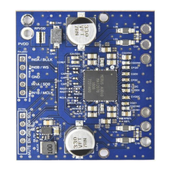
Board overview Board overview The reference board (RFB) is a reference and demonstration board for Infineon’s MA12040, MA12040P, MA12070 and MA12070P amplifiers. See the board in Figure 1 with MA12070 mounted. It contains a variety of digital/analog input, output and set-up/selection features. It also contains one on-board power supply (5 V buck converter), so only one external power supply (PVDD) is necessary. -
Page 4: General Board Specifications
User manual for MA120xxx reference boards Board overview General board specifications Number of audio channels 2 x BTL or 1 x PBTL Audio input format: o MA12040 and MA12070 Analog o MA12040P and MA12070P Digital (I Supply voltage range MA12040(P) 5 to 18 V ... - Page 5 User manual for MA120xxx reference boards Board overview Figure 2 shows the top view of the board assembly. The board has following key features, which are indicated by corresponding numbers marked with red. 1. PVDD power connector: connect PVDD 5 V to 18 V for MA12040(P) or connect PVDD 5 V to 26 V for MA12070(P) 2.
-
Page 6: Board Configuration
User manual for MA120xxx reference boards Board overview Figure 2 Schematic top view of component and connector assembly Board configuration The board is shipped with a default configuration for automatic start-up, two channels of BTL output, and default internal register settings. It is however possible to operate the board in different modes. The following configurations are possible: ... -
Page 7: Device Configuration Through I
User manual for MA120xxx reference boards Board overview Device configuration through I Multi-level technology offers the possibility to optimize for audio performance, efficiency or EMI. Depending on the application, typically one parameter is more important than the others. The amplifiers offer the flexibility to make this design trade-off by the use of different optimal modes (Power Mode Profiles or PMP), selected through internal register settings. -
Page 8: Schematic, Layout And Design Considerations
User manual for MA120xxx reference boards Schematic, layout and design considerations Schematic, layout and design considerations Figure 4 Reference board schematic Application Note 8 of 28 V 1.0 2019-04-28... - Page 9 User manual for MA120xxx reference boards Schematic, layout and design considerations Figure 5 Top side of the PCB layout Application Note 9 of 28 V 1.0 2019-04-28...
- Page 10 The RFB is cost optimized. The cost of one module including PCB, components and assembly is estimated to be $2.15 at a volume of 1000 pieces. The price of the MA120xx(P) amplifier depends on the volume and part. For performance optimization see the application note “EMC output filter recommendation” or contact Infineon. Application Note 10 of 28 V 1.0...
-
Page 11: Bom
383 K 0.063 W 1 percent 0402 (1005 RB_FB2 metric) SMD Yageo RC0402FR-07383KL 100 K 0.063 W 1 percent 0402 (1005 RB_PG metric) SMD Yageo RC0402FR-07100KL Multi-level Class D amplifier Infineon MA120xx TPS62175DQCT TPS62175DQCT Application Note 11 of 28 V 1.0 2019-04-28... -
Page 12: Design Considerations
The current design of the buck regulator generates 5 V from 26 V PVDD with approximately 85 percent efficiency. Efficiency could have been increased by increasing the inductance, which would have increased the footprint; Infineon opted for a smaller footprint instead. -
Page 13: Measurement Results
User manual for MA120xxx reference boards Measurement results Measurement results This section shows the measurement results from tests performed on a reference board, which demonstrate high audio and efficiency performance and good thermal characteristics. Measurements include: Frequency sweep Output power sweep ... - Page 14 10000 Frequency [Hz] Figure 8 THD + N vs. frequency To improve the THD + N performance use high-performance ferrite beads. See the application note – EMC output filter recommendations at www.Infineon.com Application Note 14 of 28 V 1.0 2019-04-28...
-
Page 15: Output Power Sweep
User manual for MA120xxx reference boards Measurement results Output power sweep Output power sweeps were carried out on both channels with a 1 kHz input signal. Channel 1 Channel 2 0,01 0,001 0,01 Frequency [Hz] Figure 9 THD + N vs. output power Application Note 15 of 28 V 1.0... -
Page 16: Output Spectrum
User manual for MA120xxx reference boards Measurement results Output spectrum The Figure 10 shows the output spectrum that has been obtained by applying 1 mVrms (1 kHz) input signal to both channels. This gives an output signal of -40 dBV. The noise floor for these settings is shown in the Figure 10. -
Page 17: Power Consumption And Efficiency
User manual for MA120xxx reference boards Measurement results 0,02 0,016 0,012 0,008 0,004 -0,004 -0,008 -0,012 -0,016 -0,02 0,0005 0,001 0,0015 0,002 Time (s) Figure 11 Scope capture showing 10 mV output signal on both channels Power consumption and efficiency Power consumption and efficiency measurements were obtained by using a test signal of 1 kHz and a load of 4 Ω... - Page 18 User manual for MA120xxx reference boards Measurement results Figure 13 Power loss as a function of output power Figure 14 Efficiency as a function of output power (log scale) Application Note 18 of 28 V 1.0 2019-04-28...
- Page 19 User manual for MA120xxx reference boards Measurement results Figure 15 Efficiency as a function of output power (linear scale) Application Note 19 of 28 V 1.0 2019-04-28...
-
Page 20: Emi Radiated Measurements
User manual for MA120xxx reference boards Measurement results EMI radiated measurements 3.5.1 EMI measurement setup EMC chamber LINEAR POWER SUPPLY DEVICE AUDIO R&S Spectrum UNDER Speakers SOURCE Analyzer TEST Test PC TURN TABLE Figure 16 EMI measurement set-up for radiated emission test Figure 16 shows the set-up for testing. - Page 21 User manual for MA120xxx reference boards Measurement results Figure 17 EMI-radiated measurement results. Board positioned toward antenna. Antenna position is vertical. Application Note 21 of 28 V 1.0 2019-04-28...
- Page 22 User manual for MA120xxx reference boards Measurement results Figure 18 EMI-radiated measurement results. Board positioned toward antenna. Antenna position is horizontal. Application Note 22 of 28 V 1.0 2019-04-28...
- Page 23 User manual for MA120xxx reference boards Measurement results Figure 19 EMI-radiated measurement results. Board positioned perpendicular to the antenna. Antenna position is vertical. Application Note 23 of 28 V 1.0 2019-04-28...
- Page 24 User manual for MA120xxx reference boards Measurement results Figure 20 EMI-radiated measurement results. Board positioned perpendicular to the antenna. Antenna position is horizontal. Application Note 24 of 28 V 1.0 2019-04-28...
-
Page 25: Appendix A - Sample Code
User manual for MA120xxx reference boards Appendix A – sample code Appendix A – sample code /*---------------------------------------------------------- * Title: I C basic communication set-up * Author: Rien Oortgiesen * This code demonstrates basic I C communication * using Arduino UNO together with MA120XXX devices * Use: * The code uses I C lib from Wayne Truchsess which allows repeated... - Page 26 User manual for MA120xxx reference boards Appendix A – sample code // attach interrupt handler (0 is the internal interrupt attached to pin 2) attachInterrupt (0, switchPressed, RISING); // start with LED off digitalWrite(LED, 0); // set audio_in_mode_ext I2c.begin(); I2c.write(0x20,0x27,0x28); //audio_in_mode_ext = 1 I2c.end();...
-
Page 27: Revision History
User manual for MA120xxx reference boards Appendix A – sample code Revision history Document Date of release Description of changes version 24-01-2019 Initial release Application Note 27 of 28 V 1.0 2019-04-28... - Page 28 Infineon Technologies hereby disclaims dangerous substances. For information on the types © 2019 Infineon Technologies AG. any and all warranties and liabilities of any kind in question please contact your nearest Infineon All Rights Reserved. (including without limitation warranties of non- Technologies office.
Need help?
Do you have a question about the MERUS MA120 Series and is the answer not in the manual?
Questions and answers