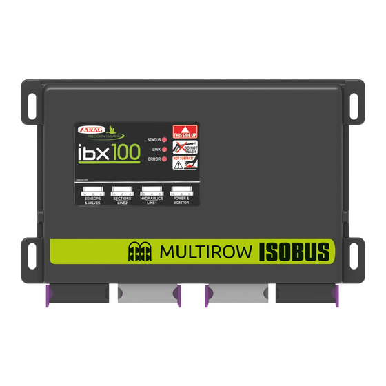
ARAG IBX100 Configuration And Maintenance Manual
Harness configurable sensors and valves
Hide thumbs
Also See for IBX100:
- Installation - use - maintenance (78 pages) ,
- Installation, use and maintenance manual (76 pages) ,
- Directions for installation, use and maintenance (56 pages)
Summary of Contents for ARAG IBX100
- Page 1 HARNESS CONFIGURABLE FOR IBX100 SENSORS AND VALVES 467001151 APPLICATION, CONFIGURATION AND MAINTENANCE...
- Page 2 This manual is an integral part of the equipment to which it refers and must accompany the equipment in case of sale or change of ownership. Keep it for any future reference; ARAG reserves the right to modify product specifications and instructions at any moment and without notice.
-
Page 3: Table Of Contents
CONTENTS CONTENTS Risks and protections before assembly.........4 Product description ..............4 Intended use ................4 Precautions ................4 Package content ...............4 Overall dimensions ..............5 Application ................5 Adapter cables ................5 Configuration ................6 10 Closing the block ..............14 11 Cleaning rules .................15 12 Technical data .................15 13 Guarantee terms ..............15 14 End-of-life disposal ..............15... -
Page 4: Risks And Protections Before Assembly
• RESPONSIBILITIES The installer must carry out "workmanlike" installations and ensure to the end user the perfect operation of the whole system both with ARAG components only and other brands' components. ARAG always recommends using its components to install control systems. -
Page 5: Overall Dimensions
176.7 Fig. 2 APPLICATION The block described in the following chapters is specific for connection to the “SENSORS & VALVES” connector of IBX100. Fig. 3 ADAPTER CABLES ADAPTER CABLES MUST BE ORDERED SEPARATELY Below is a list of the available adapter cables:... -
Page 6: Configuration
PRELIMINARY CONFIGURATION OPERATIONS CONFIGURATION -Identify which sensors and valves are required according to the type of system that is to be made in the involved agricultural equipment. -Identify the model and quantity of adapter cables to be used (see previous paragraph) according to the type of connection of each sensor and valve to be installed. - Page 7 PRELIMINARY CONFIGURATION OPERATIONS - Install the cable glands, previously prepared with O-rings, in the holes of the block: THE TIGHTENING TORQUE OF CABLE GLANDS IS 1 Nm. Fig. 9 Fig. 8 - Thread the adapter cables into the cable glands: ...
- Page 8 [ARAG SERIES 864 - 871 (*)] BLACK #SIG n.c.: not connected (*) : see the ARAG catalog for more information (**) : the input can be used only for one signal depending on the firmware configuration E.g.: CABLE CODE 4621AA10000.100 with speed signal #SIG...
- Page 9 [not supplied] COMMUNICATION can_H #SIG n.c.: not connected (*) : see the ARAG catalog for more information E.g.: CABLE CODE 4621AA10000.100 with speed signal #SIG PIN 3 PIN 2 PIN 1 Below are some examples of connection of the adapter cable wires to the terminal board of the printed E.g.: CABLE CODE 8650900.140 for proportional valve control...
- Page 10 MAIN VALVE 8650900.140 [ARAG SERIES 864 - 871 (*)] BLACK #SIG n.c.: not connected (*) : see the ARAG catalog for more information E.g.: CABLE CODE 4621AA10000.100 with speed signal #SIG PIN 3 PIN 2 PIN 1 Below are some examples of...
- Page 11 MAIN VALVE 8650900.140 [ARAG SERIES 864 - 871 (*)] BLACK #SIG n.c.: not connected (*) : see the ARAG catalog for more information E.g.: CABLE CODE 4621AA10000.100 with speed signal #SIG PIN 3 PIN 2 PIN 1 Below are some examples of...
- Page 12 CONFIGURATION - SPREADER ISOBUS SPREADER #SIG BELT SPREADER WITH SINGLE CONTROL FOR BOTH SPINNERS TYPE OF SENSOR CABLE CONNECTION OF CABLES SENSOR / VALVES (Pin) SIGNAL [ARAG CODE] ADAPTER Clamp Wire Clamp Wire Clamp Wire Digital sensor GREEN SPEED #SIG 4621AA10000.100...
- Page 13 1 SPRAYING EXTERNAL ACTIVATION #SIG [Not supplied] n.c.: not connected (*) : see the ARAG catalog for more information E.g.: CABLE CODE 4621AA10000.100 with speed signal #SIG PIN 3 Below are some examples of connection of the adapter cable wires...
-
Page 14: Closing The Block
CLOSING THE BLOCK CLOSING THE BLOCK At the end of the connection operations, close the block lid which was previously removed and use the appropriate screws. WARNING: avoid squeezing the cables by checking that the lid seat (red edge in the figure below) is completely free. Position the lid in its seat and tighten the four screws at the ends of the block. -
Page 15: Cleaning Rules
IPx5 GUARANTEE TERMS 1. ARAG s.r.l. guarantees this apparatus for a period of 360 days (1 year) from the date of sale to the client user (date of the goods delivery note). The components of the apparatus, that in the unappealable opinion of ARAG are faulty due to an original defect in the material or production process, will be repaired or replaced free of charge at the nearest Assistance Center operating at the moment the request for intervention is made. - Page 16 Only use genuine ARAG accessories or spare parts to make sure manufacturer guaranteed safety conditions are maintained in time. Always refer to the Internet address www.aragnet.com 42048 RUBIERA (Reggio Emilia) - ITALY Via Palladio, 5/A Tel. +39 0522 622011 Fax +39 0522 628944 http://www.aragnet.com...


Need help?
Do you have a question about the IBX100 and is the answer not in the manual?
Questions and answers