
Related Manuals for QSFPTEK S5600-24T8X


Summary of Contents for QSFPTEK S5600-24T8X
- Page 1 S5600-24T8X Quick Start Guide 24-Port Gigabit Ethernet L3+ Switch 24x 1G RJ45, with 8x 10G SFP+ Uplinks, Support MLAG V3.0 www.qsfptek.com V3.0 1/13...
- Page 2 Enterprise, Data Center, Metro, and HCI (Hyper-Converged Infrastructure) networks. We appreciate your decision to select S5600-24T8X. This manual is intended to help you become acquainted with the switch design and provide instructions for implementing the switches into your network.
-
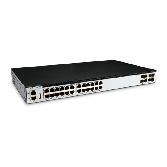
Page 3: Hardware Overview
10/100/1000BASE-T ports for Ethernet connection SFP+ Hot-swappable SFP+ ports for 1/10G connection An RJ45 console port for serial management An RJ-45 Ethernet management port A USB management port for software and configuration backupand offline software upgrade Front Panel LEDs www.qsfptek.com V3.0 3/13... - Page 4 Blinking 10/100M packets receiving or transmitting. Port not link 10G port link. Green Blinking 10G packets receiving or transmitting. SFP+ 1G port link. (Port 25-32) Amber Blinking 1G packets receiving or transmitting. Port not link Back Panel www.qsfptek.com V3.0 4/13...
-
Page 5: Installation Requirements
Cleanliness Requirements: Substance Unit Concentration limit DUST Particle/m3 ≤ 3 X 10⁴ (No visible dust on the tabletop for three days) mg/m3 mg/m3 0.006 mg/m3 0.05 mg/m3 0.01 Note: The dust particle size is ≥ 5 μm www.qsfptek.com V3.0 5/13... -
Page 6: Mounting The Switch
Connecting the RJ45 Ports 1. Connect one end of the Ethernet cable to the RJ45 port on networking equipment, such as PC, printer, server, storage, etc. 2. Connect the other end of the Ethernet cable to the switch RJ45 port. www.qsfptek.com V3.0 6/13... - Page 7 1. Insert the SFP+ module into the SFP+ port. 2. Plug a fiber patch cable to the SFP+ transceiver. 3. Connect the other end of the fiber to the device that you want to realize data communication. www.qsfptek.com V3.0 7/13...
-
Page 8: Connecting The Management Ports
2. Insert the RJ45 connector of the console cable into the console port on the switch. 3. Connect the D89 female connector on the other end of the console cable to the serial port on the computer host. Connecting the ETH Port www.qsfptek.com V3.0 8/13... - Page 9 3. Connect the RJ45 connector on the other end of the patch cable to the ETH port on the switch Connecting the USB Port 1. Prepare an Universal Serial Bus (USB) flash disk. 2. Insert the USB to the switch USB port. www.qsfptek.com V3.0 9/13...
-
Page 10: Configuring The Switch
Step 2: Set the IP address of the computer to 192.168.1.x (where "x" is any number from 2 to 254) and the subnet mask to 255.255.255.0. Step 3: Open a web browser and type http://192.168.1.1 in the address bar. Enter the default username and password (admin/admin). Step 4: Click sign-in to access the web-based configuration page. www.qsfptek.com V3.0 10/13... - Page 11 Step 3: Configure the parameters of the terminal emulation software as follows: 115200 bits per second, 8 data bits, no parity, 1 stop bit, and no flow control. Step 4: Enter the default username and password (admin/admin). www.qsfptek.com V3.0 11/13...
- Page 12 2. The cable of the configuration port (Console) is properly connected. If no problems have been found after the above checks, it is possible that the configuration cable is faulty or the parameter setting of the terminal (such as a super terminal) is incorrect, please check accordingly. www.qsfptek.com V3.0 12/13...
-
Page 13: Support And Other Resources
Product Warranty S5600 series switches are backed by a 5-year limited warranty supported by QSFPTEK. And you are eligible to apply for a return or exchange of your items within 14 days of receiving them. For more details about applying qualifications, please live chat or email sales@qsfptek.com...
Need help?
Do you have a question about the S5600-24T8X and is the answer not in the manual?
Questions and answers