Table of Contents
Advertisement
Advertisement
Table of Contents

Subscribe to Our Youtube Channel
Related Manuals for Johnson & Johnson ASP STERRAD NX


Summary of Contents for Johnson & Johnson ASP STERRAD NX
- Page 1 ® ™ STERRAD Sterilization System User’s Guide...
- Page 2 ® ™ STERRAD Sterilization System User’s Guide REF 99920 1-888-STERRAD ASP U.S.A. Customer Care Center 949.581.5799 ASP International Customer Support (Call your local ASP Customer Support Representative) www.sterrad.com © 2005 Advanced Sterilization Products. All rights reserved. Other products mentioned in this publication are trademarked by their respective owners.
-
Page 3: Table Of Contents
Contents Contents Chapter 1. Introduction How to Use This Guide........................7 If You Have Questions........................7 Chapter 2. Safety Information Personal Safety and First Aid ......................9 Personal Protective Equipment ......................10 Device Safety.............................10 Warnings, Cautions, and Notes......................11 Symbols Used on the Sterilizer and in This Guide ................11 Chapter 3. - Page 4 Contents Loading the Chamber ........................39 Selecting and Starting a Cycle ......................41 Cycle Warm Up..........................42 System Ready Screen........................42 Cycle in Progress..........................43 Canceling a Cycle........................43 Cycle Completed..........................44 Processing a Sterilized Load ......................45 Inspecting Chemical Indicators ....................45 Processing Biological Indicators ....................
- Page 5 Contents Files..............................73 Cycle History Files........................73 Calibration Files ...........................74 Diagnostic Files..........................77 Chapter 8. Maintenance Automatic Maintenance ........................79 Pressure Zeroing...........................79 Automatic Lamp Adjustment .......................80 Manual Maintenance..........................81 Disposing of Cassettes ........................81 Removing a Cassette Disposal Box....................81 Inserting a New Cassette Disposal Box .....................82 Replacing Printer Paper ........................83 Cleaning the Sterilizer Exterior......................86 Cleaning the Hydrogen Peroxide Monitor Detector Lens..............86...
-
Page 7: Chapter 1. Introduction
Introduction Chapter 1. Introduction How to Use This Guide ® ™ If you are a STERRAD Sterilizer operator, you must read the “Safety Information” and the “Introduction,” “Load Preparation,” and “Operation” chapters prior to operating the sterilizer. This “Introduction” explains the features and parts of the sterilizer. “Load Preparation” explains how to prepare and package instruments for processing. -
Page 9: Chapter 2. Safety Information
Safety Information Chapter 2. Safety Information Your safety is of primary concern to Advanced Sterilization Products (ASP). This chapter provides information on safely using the ® ™ STERRAD Sterilizer. You must read and understand the safety information in this chapter before operating the sterilizer. Always pay attention to the warnings, cautions and notes throughout this User’s Guide. -
Page 10: Personal Protective Equipment
Safety Information WARNING! RISK OF RESPIRATORY IRRITATION. Inhalation of hydrogen peroxide mist can cause severe irritation of lungs, throat, and nose. If inhalation occurs, move to fresh air. Consult a physician immediately. WARNING! CONCENTRATED HYDROGEN PEROXIDE IS TOXIC. Ingestion of hydrogen peroxide may be life-threatening. If swallowed, drink plenty of water immediately to dilute. -
Page 11: Warnings, Cautions, And Notes
Safety Information Warnings, Cautions, and Notes Warnings and cautions are accompanied by symbols surrounded by a triangle and are printed in the text in boldface italics. Warnings indicate events or conditions that can result in serious injury or death. Cautions indicate events or conditions that can result in severe damage to the equipment. -
Page 13: Chapter 3. Sterilizer Overview
Sterilizer Overview Chapter 3. Sterilizer Overview Intended Use ® ™ The STERRAD Sterilization System is a general purpose, low temperature sterilizer which uses the STERRAD NX Process to inactivate microorganisms on a broad range of medical devices and surgical instruments. This sterilizer offers an effective, safe, fast, economical, easy to use, reliable, and flexible sterilization method. -
Page 14: The Sterrad ® Nx ™ Sterilization Process
Sterilizer Overview ® ™ The STERRAD Sterilization Process As a medical professional, you may already be familiar with general sterilization principles. However, the STERRAD NX Sterilizer represents a new technology, and it requires special attention to the ways in which it differs from other sterilizers. -
Page 15: Overview Of The Sterrad ® Nx ™ Sterilization Cycle
Sterilizer Overview ® ™ Overview of the STERRAD Sterilization Cycle The STERRAD NX Sterilization Cycle consists of two phases: Exposure 1 and Exposure 2. The following information provides a brief description for each of the steps. Exposure 1 ♦ Delivery 1: The hydrogen peroxide is transferred from the cassette into the vaporizer. - Page 16 Sterilizer Overview Exposure 2 The steps in Exposure 1 are repeated. ® The STERRAD NX Sterilization Cycle Phase Order Stages Delivery 1 Vaporization Pumpdown 1 Exposure 1 Chamber Pumpdown 1 Transfer 1 Diffusion 1 Plasma Pumpdown 1 / Plasma 1 Vent 1 Delivery 2 Vaporization Pumpdown 2...
-
Page 17: The Sterrad ® Nx ™ Sterilizer And Features
Sterilizer Overview ® ™ The STERRAD Sterilizer and Features The cassette slot, the cassette drawer, the touch screen, the chamber door, the printer, and the main power switch are found on the front of the sterilizer. Cassette slot Touch screen Cassette drawer Chamber... -
Page 18: Cassette Drawer
Sterilizer Overview Figure 2. Inserting a Cassette. Cassette Drawer After processing of the cassette, the sterilizer automatically discards it into the cassette disposal box in the cassette drawer. Cassette Disposal Box The cassette drawer contains a cassette disposal box for used cassettes. The box holds three cassettes. -
Page 19: Chamber
Sterilizer Overview An internal loudspeaker emits “beep” tones to call for user attention or indicate errors. A single long beep indicates a successfully completed cycle. A series of ten short beeps indicates a canceled cycle. Chamber The chamber is where the load is sterilized. The chamber walls and door contain heaters that keep the chamber interior warm during operation. -
Page 20: Printer
Sterilizer Overview Printer The printer prints cycle reports and other information on a roll of thermal paper. The printer features easy drop-in paper loading and requires no ink cartridges. When the sterilizer power is on, the printer interior is illuminated with a blue light. Push to Paper open the... -
Page 21: Rear Panel
Sterilizer Overview Rear Panel Wire retainer Power inlet Cooling fan Option connector Network PCMCIA card connector Figure 6. Rear Panel. Power cord secured in the inlet by retainer RJ-45 socket Network cable Figure 7. Connection Panel Located on the Lower Rear of the Sterilizer. ®... -
Page 22: Touch Screen Data Entry
Sterilizer Overview Touch Screen Data Entry The following figure shows a typical data entry screen. The typewriter “keys” input the indicated character each time a key is touched. You can touch the screen with your finger or with a stylus to move the cursor from place to place. -
Page 23: Sterilizer Cart
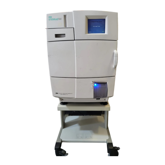
Sterilizer Overview Sterilizer Cart The Sterilizer Cart is an optional accessory that may be used to hold the ® ™ STERRAD Sterilizer. The following figure shows the sterilizer placed upon the cart. Figure 9. Sterilizer Cart The casters may be locked and unlocked by pressing on caster levers. In order for the cart to have maximum stability, the casters should be oriented in the locked position as shown in the figure above. -
Page 25: Chapter 4. Load Preparation
Load Preparation Chapter 4. Load Preparation Indications for Use ® ™ The STERRAD Sterilizer is designed for sterilization of both metal and nonmetal medical devices at low temperatures. The STERRAD sterilization process is a multiphase sterilization process that utilizes a combination of exposure to hydrogen peroxide vapor and plasma to affect sterilization. -
Page 26: Determining What Can Be Sterilized In The Sterrad ® Nx™ Sterilizer
Load Preparation 4 Note: With the exception of the 1 x 850 mm flexible endoscopes, the validation studies were performed using a validation load consisting of one instrument tray weighing 10.7 lbs. The 1 x 850 mm flexible endoscopes were validated without any additional load. -
Page 27: Items Not To Be Processed
Load Preparation ® ASP has validated the processing of non-reusable polyethylene and Teflon (polytetrafluoroethylene) medical grade tubing with the dimension and cycles listed below. These tubing claims have not been reviewed by the Food and Drug Administration (FDA): ♦ An inside diameter of 1 mm or larger and a length of 350 mm or shorter †... -
Page 28: Guidelines For Preparing Items To Be Sterilized
Load Preparation ♦ Instrument mats other than STERRAD Instrument Mats. ♦ Instrument trays other than STERRAD Instrument Trays or ® APTIMAX Instrument Trays. ♦ Implants for which the manufacturer has not specifically recommended ® sterilization in the STERRAD NX Sterilizer. Guidelines for Preparing Items to Be Sterilized 4 Note: All items must be cleaned, rinsed, and thoroughly... -
Page 29: Packaging And Loading
Load Preparation ♦ Some complex reusable medical devices may require disassembly for proper cleaning and sterilization. It is very important that you follow the device manufacturers recommendations concerning cleaning and sterilization. WARNING! POSSIBLE NON-STERILE DEVICE Loads containing moisture may result in either a non-sterile device or cycle cancellation. -
Page 30: Packaging
Load Preparation Packaging ♦ Use only STERRAD Sterilizer-compatible polypropylene sterilization ® wrap and Tyvek pouches. ♦ Do not use paper pouches or sterilization wraps containing cellulose or cotton. ♦ Do not use any wraps or packaging that are not approved by ASP or materials on the “Items Not To Be Processed”... -
Page 31: Chemical Indicators
Load Preparation Chemical Indicators ® ® ® STERRAD Chemical Indicator Strips and STERRAD SealSure Chemical Indicator Tape offer a method to verify that the load has been exposed to hydrogen peroxide in the sterilizer. Chemical indicators are not a substitute for biological indicators. If you use chemical indicator strips or chemical indicator tape, follow the Instructions for Use that accompany these items as you prepare the load. -
Page 33: Chapter 5. Operation
Operation Chapter 5. Operation Before You Start ® ™ Each time you use the STERRAD Sterilizer, follow the instructions provided in the chapter on load preparation. It is the operator’s responsibility to be familiar with the information provided in this user’s guide. -
Page 34: Inserting A Cassette
Operation STERRAD NX System ® TOUCH SCREEN TO START ® Figure 10. Touch the Screen to Start Your Cycle The screen displays the message “Please Insert New Cassette” if a new cassette is required, if the cassette in the sterilizer is expired, or if there is no cassette installed in the sterilizer. -
Page 35: Preparing The Load
Operation Figure 11. Inserting the Cassette into the Slot. 5. After a slight pause, the sterilizer pulls the cassette through the slot and the slot door closes. Cassette loading is now complete. Preparing the Load While the sterilizer is warming up, you can use this time to prepare the load. - Page 36 Operation MM/DD/YY Operator Login HH:MM:SS Legend MM: month Operator: DD: day YY: year Password: HH: hour MM: minute SS: second & BACKSP < > ENTER CAP LOCK " BACKSP Figure 12. Operator Login Screen. 1. Touch the Operator field. The cursor appears in the field. 4 Note: Operator and Password fields are case-sensitive.
-
Page 37: Entering Load Information
Operation Entering Load Information 4 Note: If your sterilizer has been configured not to require load item data, this screen will not appear. Skip to the subsection titled Cycle Notes. Enter Load Item Data The Load Item Data screen allows you to enter information about the contents of the load. -
Page 38: Cycle Notes
Operation 6. The program displays the Enter Cycle Notes screen. A barcode scanner can also be used to enter load item data. Refer to the barcode scanner Instructions for Use if your sterilizer is equipped with this option. Cycle Notes 4 Note: If your sterilizer has been configured not to require cycle notes, this screen will not appear. -
Page 39: Loading The Chamber
Operation 1. Touch the Enter Notes for Cycle field. The cursor appears in the field. 2. Use the on-screen keyboard to type your notes. 3. When data entry is complete, touch the Done button. 4. If conditions exist which prevent a sterilization cycle from starting (e.g., no cassette, hydrogen peroxide monitor blocked), a message is displayed on the screen. - Page 40 Operation 2. When placing the load on the shelves, make certain that you do not block the beam of the ultraviolet lamp in the front right corner of the chamber. Do not allow the load to touch the electrode Figure 17. The Load Should NOT Touch the Electrode. 3.
-
Page 41: Selecting And Starting A Cycle
Operation Selecting and Starting a Cycle When the load has been placed in the chamber, and the door has been tightly closed, use the System Ready screen to select the sterilization cycle appropriate for the load. MM/DD/YY System Ready HH:MM:SS SELECT CYCLE TO BEGIN STANDARD CYCLE ADVANCED CYCLE... -
Page 42: Cycle Warm Up
Operation Cycle Warm Up When changing from one type of cycle to another; i.e., from Standard to Advanced or from Advanced to Standard, the sterilizer requires time to warm up. 1. The sterilizer displays the System Warming Up message. System Warming Up... Cycle Will Automatically Start Cancel Cycle Figure 20. -
Page 43: Cycle In Progress
Operation Cycle in Progress When you touch the Start Cycle button, the sterilizer starts a “countdown clock” and begins the sterilization cycle. MM/DD/YY Cycle In Progress HH:MM:SS Cancel Cycle MM:SS Time Remaining Current Stage: Figure 21. Cycle In Progress. The Countdown Clock is Displayed. The clock displays the estimated number of minutes and seconds remaining before the cycle is finished. -
Page 44: Cycle Completed
Operation Cancel Cycle? Figure 22. Cancel Cycle Confirmation. Touch Yes or No. 2. Touch the No button to proceed with the cycle. Touch the Yes button to cancel the cycle. Once the cycle cancellation sequence begins, the screen turns red and the cancellation sequence cannot be interrupted. The cancellation sequence may take up to ten minutes to complete. -
Page 45: Processing A Sterilized Load
Operation MM/DD/YY Cycle Completed HH:MM:SS Cycle Completed Successfully CYCLE DATA: Cycle #: Cycle Name: Start Time: Completion Time: Elapsed Time: Operator: View Details Done Figure 23. Cycle Completed. 1. Touch the View Details button to display the cycle history file for the just-completed cycle. -
Page 46: Processing Biological Indicators
Operation Processing Biological Indicators Remove the biological indicator from the load and process it per its Instructions for Use. Refer to the biological indicator flow chart on the next page for additional information. Cycle Completion Flowchart Sterilization cycle completed. Review printout. - Page 47 Operation ® ® STERRAD CycleSure Flowchart ® ™ STERRAD User’s Guide...
-
Page 49: Chapter 6. Access Levels And Supervisor Tasks
Access Levels and Supervisor Tasks Chapter 6. Access Levels and Supervisor Tasks Overview Users with supervisor-level access privileges (see below) are permitted to perform a set of restricted sterilizer functions. These functions are not used in daily sterilizer operation and some of them are designed to control access, manage system records, and perform advanced diagnostic functions. -
Page 50: Additional Utilities Menu
Access Levels and Supervisor Tasks ♦ Select, view, and print all sterilizer files ♦ Run diagnostic tests and print reports ♦ Set date and time ♦ Configure sterilizer options ♦ Configure the network connection and upload data to the network Service-level access is only for use by ASP Service Representatives. -
Page 51: Date And Time Settings
Access Levels and Supervisor Tasks Service Functions are reserved for use by ASP Service Representatives. System Config allows you to set sterilizer options. Network allows you to configure the network connection. File Management allows you to select, display, and print files. User Admin allows you to add, delete, or modify operator identifications, passwords, and access levels. -
Page 52: Set Time
Access Levels and Supervisor Tasks Set Time Use the HH box to set the hour (01-12 if 12-hour format is selected, 00-23 if 24-hour format is selected). Use the MM box to set the minute (00-59) and the SS box to set the second (00-59). If 12-hour format is selected, you may only select hours 01-12, and you must touch the AM or PM buttons to indicate the correct time. -
Page 53: System Configuration
Access Levels and Supervisor Tasks System Configuration Use the System Configuration screen to set sterilizer options. Selections on this screen allow you to set the volume of the alarm loudspeaker, the time interval before the screen backlight is turned off, the language used in displays and reports, and several access, report, and connection options. -
Page 54: Vacuum Units
Access Levels and Supervisor Tasks Vacuum Units torr/mtorr expresses vacuum measurements in torr and millitorr. kPa/Pa expresses vacuum measurements in kilopascals and Pascals. This is the factory default setting. Load Data Entry Option Enabled causes the Enter Load Item Data screen to be displayed after login. -
Page 55: Backlight Conservation
Access Levels and Supervisor Tasks Backlight Conservation The lifetime of the touch screen backlight can be considerably increased if the sterilizer automatically turns it off when it is not in use. Select 15, 30, or 60 minutes to set the length of time the backlight remains on after the screen was last touched. -
Page 56: File Management
Access Levels and Supervisor Tasks File Management Use the File Management screen to select and display calibration files or diagnostic report files. Figure 27. File Management. Calibration Files Touch the Calibration Files button to display a list of calibration files created during a sterilizer calibration. -
Page 57: User Administration
Access Levels and Supervisor Tasks User Administration Use the User Administration screen to add, modify, or delete user names, passwords, and access levels. A button on this screen allows you to upload user information over your network from a remote host (if configured for network connection). -
Page 58: Add User
Access Levels and Supervisor Tasks Add User Use the Add User screen to enter a new user’s identification, password, and access level. MM/DD/YY Add User HH:MM:SS Access Level: Operator: Operator (choose one) Cancel Supervisor Password: Done & BACKSP < > ENTER CAP LOCK "... -
Page 59: Modify User
Access Levels and Supervisor Tasks Modify User Use the Modify User screen to modify an existing user’s identification, password, and access level. MM/DD/YY Modify User HH:MM:SS Select User: Operator "A" name Operator "B" name Operator "C" name Edit User Delete User Done Figure 30. -
Page 60: Upload User Data
Access Levels and Supervisor Tasks ♦ To change the user’s operator name, make changes in the Operator field. ♦ To change the user’s password, make changes in the Password field. ♦ To change the user’s access level, select the desired Access Level. You may only choose “Operator”... -
Page 61: Steps To Upload A User Database
Access Levels and Supervisor Tasks Steps to Upload a User Database To upload a list of user identifications and passwords, perform the following steps: 1. Create an ASCII text file called "users.rec" that contains the user identifications, passwords, and access levels. Each entry should be separated by a comma only (no spaces). -
Page 62: Diagnostics
Access Levels and Supervisor Tasks Diagnostics Touch the Diagnostics button to start automatic diagnostic testing of the sterilizer. When started, the diagnostics function prompts you to select one of two types of tests (either Temperature or Other Tests). If Other Tests is selected, the sterilizer runs ten operator-assisted tests of the sterilizer subsystems. -
Page 63: Chapter 7. Reports And Files
Reports and Files Chapter 7. Reports and Files Displayed Reports Users with Operator-level access can display the System Summary file and Cycle History files. Users with Supervisor-level access can display the System Summary file, Cycle History files, as well as Calibration files and Diagnostic files. - Page 64 Reports and Files Print Summary prints the contents of the System Summary file. Touch the scroll bars to scroll through the file. An explanation of the System Summary file is provided in the following table Back returns you to the previous screen. System Summary File Summary Item Description...
- Page 65 Reports and Files Summary Item Description Comments Notepad Indicates whether Cycle Notes Configurable through System entry is required Configuration screen Alarm Volume Current setting of alarm volume Configurable through System Configuration screen Backlight Conservation Current setting of backlight Configurable through System conservation timer Configuration screen Facility Name...
- Page 66 Reports and Files Summary Item Description Comments System Board Revision Revision number of system circuit Determined by sterilizer board operation Network Option When enabled, network connection Configurable through System is supported Configuration screen Pressure Zeroing Current setting for the pressure Set by ASP Service zeroing procedure Pressure Zeroing Time...
-
Page 67: Cycle History
Reports and Files Cycle History Cycle history data is stored in the sterilizer’s memory. The memory holds data from the last 50 cycles. After 50 cycles are completed, the oldest cycle history record is overwritten with new data from the 51 cycle. -
Page 68: Printed Reports
Reports and Files Printed Reports Every time a cycle is completed, a cycle completion report is printed. Depending upon how your sterilizer has been configured, the report will either be a short-format report or a long-format report. Both reports extract data from the cycle history record created by the cycle. -
Page 69: Long Report
Reports and Files Long Report The long-format report lists detailed information about the cycle, shows the cycle status, lists the date and duration of the cycle, shows operator and load identifying information, and provides detailed data about the operation of the sterilizer, including temperatures, pressures, plasma measurements, and sterilant concentrations throughout the cycle. - Page 70 Reports and Files Software Version: xxx Pressure: xxxTorr xxxTorr Facility Name: xxxxxx Chamber Temp: xx.xC xx.xC Department Name: xxxxxx Door Temp: xx.xC xx.xC Sterilizer ID: Vaporizer Temp: xx.xC xx.xC Serial #: xxxxxxxx Condenser Temp: xx.xC xx.xC Cycle #: xxxx Daily Cycle #: (Chamber Pumpdown 1) Operator: Operator A...
- Page 71 Reports and Files (Plasma Pumpdown 1) Vaporizer Temp: xx.xC xx.xC Start Time End Time Stage Time Condenser Temp: xx.xC xx.xC XX:XX:XX XX:XX:XX XX:XX:XX H2O2 Monitoring(mg/l): x.x x.x Sensor ----------- ------- ------- (Vaporization Pumpdown 2) Pressure: >30Torr >30Torr Start Time End Time Stage Time Chamber Temp: xx.xC xx.xC XX:XX:XX...
- Page 72 Reports and Files (Diffusion 2) Start Time End Time Stage Time Process Complete XX:XX:XX XX:XX:XX XX:XX:XX Sensor ----------- ------- ------- Pressure: xxxTorr xxxTorr Validated by: _____________________ Chamber Temp: xx.xC xx.xC Door Temp: xx.xC xx.xC Vaporizer Temp: xx.xC xx.xC Cassette Bar Code: XXXXXXXXXX Condenser Temp: xx.xC xx.xC Number of Cycles Available=X...
-
Page 73: Files
Reports and Files Files ® ™ The STERRAD Sterilizer creates, stores, displays, prints, and can upload over a network several files of sterilizer and cycle-related data. These files include cycle history files. Each file is explained in the following sections. Cycle History Files Cycle history files contain very detailed information about each sterilization cycle. -
Page 74: Calibration Files
Reports and Files Calibration Files Calibration files are generated every time the sterilizer is recalibrated. The files contain details about the inputs and outputs from calibrated sensors. This information ensures that the sterilizer is operating within its calibration limits and is useful to ASP Service Representatives when performing maintenance or service. - Page 75 Reports and Files Cond Heater xxxxxxxxxxxx Temp Calibration/Verification Report Cond Heater xxxxxxxxxxxx ..... Cond Heater xxxxxxxxxxxx Cond Heater xxxxxxxxxxxx File Name: /xxxxxxxxxxxxx 50C Verify Point(C): xx.x...
- Page 76 Reports and Files Thermistor Resistance Adjustment Report ....... . . File Name: temprxxxxxxxx Last Verified:...
-
Page 77: Diagnostic Files
Reports and Files H2O2 Monitor Calibration ....... . . H2O2 Monitor A: x.xxexx H2O2 Monitor B: x.xxexx... - Page 78 Reports and Files DIAGNOSTICS REPORT Fan Test ....FAN TEST PASSED/FAILED Time Stamp: MM/DD/YY File Name: /xxxxxx HH:MM:SS Power Supply Test 3.3 Volts Power Supply: x.x Sound Test 5 Volts Power Supply: SOUND TEST PASSED/FAILED 12 Volts Power Supply: xx.x...
-
Page 79: Chapter 8. Maintenance
Maintenance Chapter 8. Maintenance 4 Note: Repairs and adjustments should only be attempted by experienced technicians who are fully trained to ® ™ maintain and repair the STERRAD Sterilizer. Use of unauthorized parts for maintenance or repair could cause personal injury, result in costly damage, or sterilizer malfunction and voids the warranty. -
Page 80: Automatic Lamp Adjustment
Maintenance Pressure Zeroing Report ....... . . Time Stamp MM/DD/YY HH:MM Result: [PASS/FAIL] Chamber Offset:... -
Page 81: Manual Maintenance
Maintenance Manual Maintenance The following maintenance procedures are performed by the user.: ♦ Disposing of cassettes. ♦ Inserting a new cassette disposal box. ♦ Replacing the printer paper roll. ♦ Cleaning the sterilizer exterior. ♦ Cleaning the hydrogen peroxide monitor detector lens. ♦... -
Page 82: Inserting A New Cassette Disposal Box
Maintenance 3. Fold the flaps over the top of the box. Push the tab of one flap into the slot of the other flap. Figure 46. Push Tab Into Slots Figure 47. Closed Box Can Now Be Discarded 4. The closed box is now ready for disposal. It can be discarded as directed by your facility’s disposal procedures. -
Page 83: Replacing Printer Paper
Maintenance Replacing Printer Paper When the printer paper roll is empty, the sterilizer displays a message “Printer is out of paper. Please load a new roll.” 1. Open the printer by pressing the top button. The printer door drops forward. Figure 46. - Page 84 Maintenance 3. Insert a new paper roll as shown in the following figure. The paper should feed from the top of the roll. Figure 48. Insert a New Paper Roll. 4. Pull a short length of paper over the top of the printer door. 5.
- Page 85 Maintenance 6. Hold the paper in place as you push the door shut. Figure 50. Hold the Paper as You Shut the Printer Door. Press the Paper Advance Button. 7. Push the bottom button to advance the paper. Check the alignment of the paper and make certain it does not jam or misfeed.
-
Page 86: Cleaning The Sterilizer Exterior
Maintenance Cleaning the Sterilizer Exterior 4 Note: Do not attempt to clean the chamber, door, interior surfaces, shelves, or electrode. If these items need cleaning, in the U.S.A. call the ASP Customer Care Center. Internationally, call your local ASP Customer Support Representative for assistance. The sterilizer exterior can be cleaned with a soft cloth and a mild, nonabrasive detergent solution if necessary. -
Page 87: Replacing The Air Filter
Maintenance Figure 51. Hydrogen Peroxide Monitor Lens. ♦ Always use a lint-free cloth to clean the lens. ♦ Moisten the cloth with isopropyl alcohol. Never use an abrasive cleanser. Replacing the Air Filter The air filter should be replaced when it is clogged with dust or debris. Periodically check the air filter for dust and debris. -
Page 88: Pcmcia Card Handling And Replacement
Maintenance Location of nut Figure 52. Air Filter. 4. Slide the new air filter into the sterilizer until it is firmly seated. 5. Replace and tighten the nut that attaches the air filter to the sterilizer. 6. Discard the used air filter as directed by your facility’s policy. PCMCIA Card Handling and Replacement The PCMCIA card contains the flash memory used to store cycle data. - Page 89 Maintenance Figure 53. PCMCIA Card. 2. Orient the PCMCIA card so that the side of the card shown in the following figure faces up. 3. Insert the card into the PCMCIA card slot as shown below. Eject button Figure 54. PCMCIA Card Partially Inserted. 4.
-
Page 90: Sterilizer Disposal
Maintenance Eject PCMCIA button card in slot Figure 55. PCMCIA Card Seated in the Slot. Alternatively, you may choose to save the PCMCIA card for your records. If you wish to save the card, replace the PCMCIA card in your sterilizer with a new card. -
Page 91: Chapter 9. Troubleshooting
Troubleshooting Chapter 9. Troubleshooting Note: Repairs and adjustments should only be made by ASP trained and authorized personnel. Most sterilizer operating problems are accompanied by a system message. These messages are useful in determining the source of the problem. In many cases you can take remedial actions to correct the source of the problem and thereby return the sterilizer to normal operation. -
Page 92: System Messages
Troubleshooting System Messages Some system messages indicate conditions that you may be able to remedy. Refer the following table for details. 4 Note: If a system message is not found in the following table, there is no remedy available that you may safely perform. - Page 93 Troubleshooting System Message Probable Cause Suggested Remedy H2O2 CURVE AREA The calculated H area under Run diagnostics. Call your ASP TOO LOW the time-temperature curve is Customer Care Representative. less than the threshold value set in the CCF. H2O2 RATE CONSTANT The calculated rate constant for Run diagnostics.
-
Page 94: Diagnostic Messages
Troubleshooting System Message Probable Cause Suggested Remedy UNABLE TO LIGHT The plasma did not light during Run diagnostics. Call your ASP PLASMA. USE EXTRA canceled cycle. Customer Care Representative. CAUTION WHEN HANDLING THIS LOAD. UNABLE TO OPEN ONE A bad or missing PCMCIA Call your ASP Customer Care SECOND DATA FILE compact flash memory. - Page 95 Troubleshooting Message Probable Cause Suggested Remedy volts. Representative. 3.3 VOLT SUPPLY HIGH 3.3 volt DC supply > 3.96 Call your ASP Customer Care volts. Representative. 3.3 VOLT SUPPLY LOW 3.3 volt DC supply < 2.64 Call your ASP Customer Care volts.
- Page 96 Troubleshooting Message Probable Cause Suggested Remedy CASSETTE MOTOR Cassette motor not functional. Verify cassette is inserted all the FAILURE way in. If problem persists, call your ASP Customer Care Representative. CASSETTE SYSTEM System could not Call your ASP Customer Care TIMEOUT communicate with delivery Representative.
- Page 97 Troubleshooting Message Probable Cause Suggested Remedy NOT DROP CHAMBER2 Chamber heater/sensor not Call your ASP Customer Care TEMPERATURE DID functioning within Representative. NOT RISE specification. COLLECTION BOX Collection box is not present Verify collection box is present FAILURE – FULL or properly positioned.
- Page 98 Troubleshooting Message Probable Cause Suggested Remedy CONDENSER Thermistor disconnected. Call your ASP Customer Care TEMPERATURE RAILED Representative. DELIVERY VALVE Delivery valve mechanical Call your ASP Customer Care SENSOR READ CLOSED failure. Representative. DELIVERY VALVE Delivery valve mechanical Call your ASP Customer Care SENSOR READ OPEN failure.
- Page 99 Troubleshooting Message Probable Cause Suggested Remedy NEEDLE Care Representative. FAILED TO RETRACT Needle motor not functional. Verify needles retract. If problem NEEDLE persists, call your ASP Customer Care Representative. HIGH PLASMA POWER Plasma power out of Run diagnostics. Call your ASP specification.
- Page 100 Troubleshooting Message Probable Cause Suggested Remedy VACUUM Leak in chamber or wet load Remove load. Verify door is INSUFFICIENT FOR in chamber. closed. If problem persists, call PLASMA your ASP Customer Care Representative. VACUUM SENSOR Vacuum valve sensor failure. Call your ASP Customer Care STUCK CLOSED Representative.
-
Page 101: Asp Customer Care Center
Troubleshooting Message Probable Cause Suggested Remedy CLOSED failure. Representative. VENT VALVE STUCK Vent valve mechanical Call your ASP Customer Care OPEN failure. Representative. ASP Customer Care Center If you encounter a problem or a system message that is not covered in the this user’s guide, do not attempt to perform repairs or adjustments to the ®... -
Page 103: Appendix A. Warranties And Software License
Appendix Appendix A. Warranties and Software License Advanced Sterilization Products Commercial Warranty ® The STERRAD Sterilizer and reusable accessories supplied by Advanced Sterilization Products (ASP) are warranted to be free from defects in materials and workmanship for a period of one (1) year from the date of installation, when properly installed, maintained and used for their intended purpose. -
Page 104: Advanced Sterilization Products Software License
Appendix examination by an ASP Service Representative, the previously repaired portion of the unit is found to be defective within the period specified above, and ASP is satisfied that the failure was due to defective materials and/or workmanship, ASP will, at its option, repair or replace the defective parts without charge. - Page 105 Appendix This license agreement is terminated if you tamper with the hydrogen peroxide container or use sources of hydrogen peroxide other than Certified ® ASP Hydrogen Peroxide containers in your STERRAD Sterilizer. Any ® warranties associated with this STERRAD Sterilizer are hereby ®...
-
Page 107: Appendix B. Consumables, Accessories, And Additional Parts
Appendix Appendix B. Consumables, Accessories, and Additional Parts Consumable Products Product Code Description ® ™ STERRAD Cassette 10133 5 cycles per cassette, 5 cassettes per case. Thermal Printer Paper Roll 10305 12 rolls of replacement printer paper. Cassette Disposal Box 10306 10 collection boxes per case. - Page 108 Appendix STERRAD® Consumables Product Code ® CycleSure Biological Indicator 14324 ® ® STERRAD SealSure Chemical Indicator Tape 14202 ® STERRAD Chemical Indicator Strips 14100 ® ® Tyvek Pouches and Rolls with STERRAD Chemical Indicator Visit www.sterrad.com for a complete list of pouches, rolls, ®...
-
Page 109: Appendix C. Sterrad ® Nx ™ Sterilizer Specifications
Appendix Appendix C. ® ™ STERRAD Sterilizer Specifications Power Single phase, offered in two voltage ranges: 99-132 VAC~, 47-63 Hz, 16A 180-264 VAC~, 47-63 Hz, 10A Dimensions H 33 in. (84 cm), W 22 in. (56 cm), D 32 in. (81 cm). Footprint: fits onto 23 in. - Page 110 Appendix Humidity Operating: 10% – 85% up to 30 linearly decreasing from 85% at 30 C to 70% at 40 Storage: 10% – 100% (rainfall will be permitted). Altitude/Pressure Operating altitude up to 3048 m (10,000 ft). Atmospheric pressure 70 kPa – 106 kPa (700 mbar – 1060 mbar), (20.7 in.
Need help?
Do you have a question about the ASP STERRAD NX and is the answer not in the manual?
Questions and answers