SICK CDB620 Operating Instructions Manual
Connection module for 1d/2d code reader or rfid interrogator
Hide thumbs
Also See for CDB620:
- Operating instructions manual (9 pages) ,
- Operating instructions manual (26 pages) ,
- Operating instructions manual (9 pages)
Advertisement
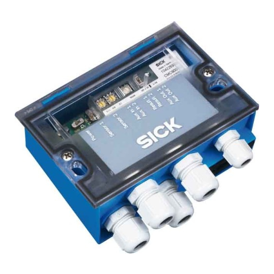
C D B 6 2 0
Anschlussmodul
für 1D/2D-Codeleser
oder RFID-Interrogator
B e t r i e b s a n l e i t u n g
1. Produkteigenschaften
Basis-Anschlussmodul zum Anschluss eines SICK Sensors an
■
Host, CAN-Scanner-Netzwerk, Peripherie und Stromversorgung
Unterstützte Sensoren: Barcodescanner CLV42 x . . . 4 5 x , CLV6xx,
■
CLV480 oder CLV /X 4 9 0 , Image Code Reader I C R 84x-2/85x-2
sowie RFID-Interrogatoren RFH6xx
Basis zur Aufnahme eines optionalen CMC600 (Connection
■
Module Cloning) für externe Speicherung der Sensor-Parameter,
Aktivierung von Betriebsarten und Erweiterung des Sensors um
jeweils zwei Schaltein- und -ausgänge (abhängig vom Sensortyp)
9-pol. D-Sub-Stecker intern, für Anschluss der Aux-Schnittstelle
■
(RS-232) an PC zur Konfiguration/Diagnose des Sensors
Klemmen für Host-Schnittstelle, CAN-Bus (CDB620-101: 2x M12-
■
Steckverbindungen), Schaltein- und -ausgänge, Stromversorgung
Von außen sichtbar: LEDs zur Anzeige von aktiven Schaltein- und
■
ausgängen sowie Schalterstellungen der Modulkonfiguration
Schutzart IP 65 (nicht durch UL geprüft)
■
Montierbar bei geschlossenem Deckel
■
Wartungsfrei
■
UL-zertifiziert bei Verwendung eines folgenden Netzgeräts:
■
UL60950-1:
LPS- oder Class-2-Netzgerät
UL508:
Class-2-Netzgerät
Weitere Produktinformationen, PC-Programm „CLV-Connect":
Siehe „www.sick.com"
EG-Konformitätserklärung:
Auf Anforderung
2. Voraussetzungen zur Installation und Inbetriebnahme
Anschlusspläne in CLV-Connect (auf CD „Manuals & Software",
■
die dem Sensor beiliegt, oder via Internet)
Versorgungsspannung DC 24 V, erzeugt nach IEC 742
■
3. Montage
Stets freier Zugang zum internen Stecker „AUX" erforderlich für
■
Zugriff auf den Sensor über RS-232 (Konfiguration/Diagnose)
Maximale Leitungslänge zwischen CDB620 und Sensor beim
■
Einsatz von Verlängerungsleitungen: 10 m (RS-232-Schnittstelle!)
Abgenommener Deckel mit Anschlussbild um 180° gedreht in
■
Parkposition arretierbar
8012119/TK38/2009-10
Sensor
Licht-
schranke
(Lesetakt)
Photo reflex
"Sensor 1"
switch
(Reading clock)
"Sensor 2"
Schalter/switch
Teach-in matchcode
Connection Module
for 1D/2D Code Reader
or RFID Interrogator
O p e r a t i n g I n s t r u c t i o n s
1. Features
Basic module for connecting a SICK sensor to the host, CAN
■
scanner network, peripheral equipment, and power supply
Supported sensors: bar code scanners CLV 42x to 4 5x, CLV6xx,
■
CLV480 or CLV /X 4 9 0 , image code readers I C R 84x-2/85x-2,
and RDIF Interrogators RFH6xx
Basis for optional CMC600 (Connection Module Cloning) inte-
■
gration for external storage of the sensor parameters, activation
of operating modes as well as extension of the sensor with each
of two switching inputs and outputs (depends on sensor type)
9-pin internal D-Sub plug, for connecting the Aux interface
■
(RS 232) to a PC for configuring/troubleshooting the sensor
Terminals for host interface, CAN bus (CDB620-101: 2 x M12
■
connections), switching inputs/outputs, and power supply
Externally visible LEDs for displaying active switching inputs and
■
outputs, as well as switch settings for module configuration
Enclosure rating IP 65 (not tested by UL)
■
Installation possible with closed cover
■
Maintenance-free
■
UL certificated when the following power supply is used:
■
UL60950-1:
LPS or Class 2 power supply
UL508:
Class 2 power supply
Further Product Information, "CLV-Connect" PC Program:
See "www.sick.com"
EC Conformity Declaration:
On request
2. Installation and Commissioning Requirements
Connection diagrams in CLV-Connect (on the "Manuals &
■
Software" CD, provided with the sensor or from the Internet)
24 V DC power supply generated in accordance with IEC 742
■
3. Installation
Permanent access to internal "AUX" plug is required for access to
■
the sensor via RS 232 (configuration/troubleshooting)
Max. cable length between CDB620 and sensor if extension
■
cables are used: 10 m (32.8 ft) because of RS 232 interface
Cover with connection diagram can be removed, rotated through
■
180°, and locked in park position
© SICK AG · Division Auto Ident · Germany · All rights reserved
"Aux"
CMC600
"CAN"
CDB620
"Host"
"Result 1"
"Result 2"
"Aux Out 1"
"Aux Out 2"
"Aux In 1"
"Aux In 2"
10 ... 30 V DC
PC
CAN Bus
HOST
SPS/PLC
SPS/PLC
1 # 6
Advertisement
Table of Contents

Subscribe to Our Youtube Channel
Related Manuals for SICK CDB620


Summary of Contents for SICK CDB620
- Page 1 Cover with connection diagram can be removed, rotated through Abgenommener Deckel mit Anschlussbild um 180° gedreht in ■ ■ Parkposition arretierbar 180°, and locked in park position 8012119/TK38/2009-10 © SICK AG · Division Auto Ident · Germany · All rights reserved 1 # 6...
- Page 2 S 7 (Term422) RS 422 termination (receiver): ON: Widerst. 120 Ohm zugeschaltet ON: 120 Ohm resistor connected OFF: keine Terminierung OFF: No termination 2 # 6 © SICK AG · Division Auto Ident · Germany · All rights reserved 8012119/TK38/2009-10...
-
Page 3: Elektrische Installation
CDB620. The Aderquerschnitte unter Berücksichtigung der im CDB620 ein- valid standards must be observed. 8012119/TK38/2009-10 © SICK AG · Division Auto Ident · Germany · All rights reserved 3 # 6... - Page 4 (siehe Betriebsanleitung des Sensors). To do so, connect the PC to the “AUX” plug on the CDB620 Hierzu PC mit 3-adriger RS-232-Datenleitung (Nullmodem- using a 3-core RS 232 data cable (null modem cable) or leitung) an Stecker „AUX“...
-
Page 5: Technische Daten
6) Using the extended operation temperature –25 to +40 °C (–13 to +104°F), the UL certification for the connection module and the connected sensor is not longer valid. 8012119/TK38/2009-10 8012119/TK38/2009-10 © SICK AG · Division Auto Ident · Germany · All rights reserved 5 # 6... -
Page 6: Fehlersuche
Cold-resistent cable (max. –35 °C (–31 °F)) for connecting the CLV480, CLV/X490 with integrated heater, 10 m (32.8 ft), connector cover (IP 65) with parameter memory, with 15-pin D-Sub HD connector for CDB620 as well as a cable with open end (power supply), suitable for track chain use 2014054 RS-232-Datenleitung (SICK Nullmodemleitung), 3 m, geschirmt, mit 2 x 9-pol.
Need help?
Do you have a question about the CDB620 and is the answer not in the manual?
Questions and answers