Inficon LDS3000 Original Operating Instructions
Mass spectrometer module
Hide thumbs
Also See for LDS3000:
- Original operating instructions (138 pages) ,
- Translation of the original operating instructions (170 pages)
Table of Contents
Advertisement
Quick Links
Advertisement
Table of Contents

Related Manuals for Inficon LDS3000


Summary of Contents for Inficon LDS3000
- Page 2 Translation of the original operating instructions Typenbez. LDS3000 Produktbeschreibung Mass spectrometer module Catalog no. 560-300 MS-Module 2.41 from software version Document no. jiqa54de1-04 (1512)
- Page 3 This document applies to the software version stated on the title page. Documents for other software versions are available from our sales department. Reprinting, translation, and duplication require written confirmation from INFICON GmbH.
-
Page 4: Table Of Contents
Content About these instructions ......6 Target groups ..........6 Other associated documents . - Page 5 Maintenance ........67 Maintenance at INFICON ........67 General maintenance information .
- Page 6 Appendix ........74 EC Declaration of Incorporation ......74 Declaration of Contamination .
-
Page 7: About These Instructions
About these instructions Target groups These operating instructions are intended for the owner and for technically qualified personnel with experience in leak detection technology and integration of leak detec- tion devices in leak detection systems. In addition, the installation and use of the unit require knowledge of electronic interfaces. - Page 8 Marking Meaning ► Instruction 1, 2, 3, ... Several instructions in a fixed order Result of an action About these instructions...
-
Page 9: Safety
Safety Intended use The unit is a modular leak detector for installation in industrial leak detection sys- tems. The test gases that can be measured with the unit are helium and hydrogen (forming gas). The unit is suitable for pressure and vacuum testing. The unit is used for integral test- ing in a vacuum and for local testing with a sniffer line. -
Page 10: Operator Requirements
Personnel qualifications ► All work must be performed only by technically qualified specialists who have been trained on the unit. ► Allow personnel in training to work on the unit only under the supervision of tech- nically qualified specialists. ► Make sure that the authorized personnel have read and understood these instruc- tions and all other applicable documents (see chapter 1.2, page 6), especially the... - Page 11 Interference with pacemakers The magnets in the mass spectrometer module can affect the proper functioning of pacemakers. ► Always comply with the distances recommended by the pacemaker manufactur- er without fail. Kinetic energy If the rotating parts in the turbo molecular pump are blocked because of some dam- age, high centrifugal forces must be absorbed.
-
Page 12: Shipment, Transport, Storage
Plug for Output Plug for Gauges Exit operating instructions USB flash-drive with instructions, 3D drawings and videos ► Please check the scope of delivery of the LDS3000 for completeness after re- ceipt. Transport Damage due to unsuitable packaging material Transport in unsuitable packaging material can damage the device. -
Page 13: Description
The MSB box outputs data on digital interfaces to the control unit CU1000, I/O mod- ule IO1000 or bus module BM1000. The mass spectrometer module is part of the leak detection system LDS3000. Es can be operated in a test system together with a bus module or I/O module and a data cable without additional INFICON accessories. -
Page 14: Device Setup
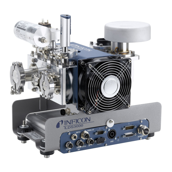
4.2.1 Overall device Fig. 1 Mass spectrometer module LDS3000 a. Connection block. Connections for test system, backing pump, pressure sensor PSG500, internal calibration leak and sniffer line, see also Fig. 2. b. Pressure sensor PSG500 for measuring the pressure of the backing pump c. -
Page 15: Connection Block
4.2.2 Connection block Fig. 2 Connection block Connection Ultra Connection Fine/Sniffer Connection Gross/Forepump 4.2.3 MSB box Fig. 3 MSB box connections OUTPUT Connection for gas ballast and three valves Connection plug arrangement Valve 2 (gas ballast), 24 V, max.1 A Valve 3 (not used, reserve) Valve 4 (not used, reserve) Valve 6 (not used, reserve) - Page 16 SNIFFER Electrical connection for the sniffer line GAUGES, EXT Connection for optional external service gauges (0°... 10 V/0 … 20 mA) for INFICON Service Connection plug arrangement +24-V-Output, max. 200 mA Input for P3 service gauge, 0 ... 10 V...
-
Page 17: Technical Data
SERVICE RS232 connection for INFICON Service I/O / ANYBUS CONTROL UNIT Connection for I/O or bus module or control unit The connections "I/O Anybus" and "Control Unit" have the same functions. You have the choice of connecting: – Control unit CU1000 + I/O module IO1000 –... -
Page 18: Ambient Conditions
1 x 10 Filter ZERO time Filter mode I•CAL Gas percentage H2 (M3, He) 100 % Gas ballast I/O module protocol ASCII Calibration request Calibration factor VAC/SNIF Mx (for vacuum, sniffer and all masses) Cathode selection Auto Cat1 Compatibility mode LDS3000 Description... - Page 19 Parameters Factory setting Config. Analog output 1 Leak rate mantissa Config. Analog output 2 Leak rate exponent Config. Analog output scale 0.5 V / decade Configuration of digital outputs Pin 1: Trigger 1, inverted Pin 2: Trigger 2, inverted Pin 3: Trigger 3, inverted Pin 4: Trigger 4, inverted Pin 5: Ready Pin 6: Error, inverted...
-
Page 20: Installation
Installation Adjust the position of the connections to the installation di- mensions In order to ideally match the installation position space, the MSB box can be turned and rotated. The MSB box is seated in two guide rails and can be pushed into the housing from the left or from the right. -
Page 21: Installing The Mass Spectrometer Module On The Test System
Installing the mass spectrometer module on the test system The mass spectrometer module can be mounted in any position. Fig. 5 Components of a fastener Hexagon socket head screw M8 x 50 Nut M8 (self-locking) Washer Base frame MO bearing Spring rubber Test system MSB box guide... -
Page 22: Connecting The Mass Spectrometer Module To The Test System
The following information applies to the use of helium as a test gas. To reach the MDLR, the following conditions must be met: – The LDS3000 must be in operation for at least 20 minutes. – Ambient conditions must be steady (temperature, no vibrations/shocks, clean environment) –... -
Page 23: Establish Component Connection
Turbo molecular pump speed Connection 1000 Hz 1500 Hz MDLR: 5 x 10 mbar l/s 1 x 10 mbar l/s 0.2 mbar 0.2 mbar Ultra temporary (< 3 s): 0.2 mbar 0.4 mbar 5 l/s 6 l/s MDLR: 1 x 10 mbar l/s 5 x 10 mbar l/s... -
Page 24: Establish Electrical Connections
Establish electrical connections All electrical connections run from and to the MSB box. Material damage if power supply pack has the wrong specifications or is con- nected improperly A power supply pack that has the wrong specifications or is connected improperly can destroy the unit. -
Page 25: Operation
Operating instructions XL sniffer adapter • Interface protocols LDS3000 The paths listed in the following sections refer to the operation of the mass spectrom- eter module with the control unit CU1000. If the bus module or the I/O module is used, the actions must be implemented within the scope of the protocol that is used. -
Page 26: Default Settings
"Loading and sav- ing parameters" on page – Compatibility mode for LDS1000 – Compatibility mode for LDS2010 – Operation mode LDS3000 – Operating mode XL sniffer adapter Control unit Settings > Set up > Compatibility > Compatibility mode Settings > Set up > Accessories > XL Sniffer A. - Page 27 LDS2010 LDS3000 Trigger 1 (sniffer LED, relay exit, au- Control of sniffer LED, PWM audio Control of sniffer LED, audio outputs dio signal) outputs an the control unit for active an the control unit for active speak- speakers Limit Low/High (ser. Interfaces, dis-...
-
Page 28: Select Gas Type (Mass)
LDS2010 LDS3000 Pressure / leak rates units (VAC/ Control unit and rest separated SNIF) for all interfaces Password 3 levels 5 levels only via control unit Key-operated switch Affects only control unit Affects only control unit (must be connected externally (see "Key-op-... - Page 29 – Prompt for calibration by the system Switching off the pre- The device tests the installed preamplifier during calibration. You can switch off of amplifier test the amplifier test. This increases the speed of the calibration, but reliability drops off. –...
-
Page 30: Internal Calibration
Calibration Particularities external – Vacuum mode: With external calibration leak – Auto tune (mass adjustment) installed in the – Determining the calibration factor after test system tuning the signal of the calibration leak – Sniffer mode: with external calibration leak –... -
Page 31: External Calibration
Opening/closing the Opening/closing the calibration leak. If the calibration leak is opened using the con- calibration leak trol unit or the interface, then no internal calibration can take place. The calibration leak must first be closed again. – 0 Closed –... - Page 32 Leak rate of external Define the leak rate of the calibration leak you wish to use during calibration. Cali- calibration leak sniff- bration will not be possible unless you enter the value here. A specific leak rate must be set for each gas (mass). 1E-7 ...
-
Page 33: External Dynamic Calibration
Fig. 6 External calibration with IO1000 using the example of sniffer line SL3000XL, de- scription of PLC inputs and outputs: see page 48 6.5.3 External dynamic calibration Incorrect calibration because of operating temperature that is too low Calibrating the device in the cold state can deliver incorrect measurement results. ►... - Page 34 1 Open external calibration leak or hold sniffer line to calibration leak. 2 Start measurement. 3 Wait until the leak rate signal is optimally suited to the normal measurement se- quence of the plant. 4 Start calibration: Control unit: Functions > CAL > dynamic LD protocol: 4, parameter 2 ASCII protocol: *CAL:DYN...
-
Page 35: External Calibration With Sniffer Line Sl3000Xl (Accessories)
Fig. 7 External dynamic calibration with IO1000 using the example of sniffer line SL3000XL, description of PLC inputs and outputs: See page 48 6.5.4 External calibration with sniffer line SL3000XL (accessories) The procedure complies with that of external or external dynamic calibration in sniffer mode. - Page 36 ► Start test: Control unit: Functions > CAL > Test int. LD protocol: 4, parameter 4 ASCII protocol: *CAL:PROOFINT IO1000: CAL test internal, see from page 48 Test is performed automatically. 6.5.5.2 Calibration using the external calibration leak test ►...
-
Page 37: Entering The Calibration Factor
6.5.6 Entering the calibration factor 6.5.6.1 Calibration factor sniffing Entry of the calibration factors for masses 2, 3, 4 in low flow and in high flow. The values will be overwritten during the next calibration. "High Flow-" or XL settings are available only in operating mode "XL Sniffer Adapt- er". - Page 38 6.5.7.1 Setting machine and sniff factor manually Mass spectrometer module calibrated internally. 1 Measure external calibration leak using the test system. The unit indicates a leak rate that is too low based on the split flow ratio. 2 Setting machine or sniff factor, see below. ...
-
Page 39: Starting And Stopping The Measurement
2 Open external calibration leak and valve (if present) between the leak detector and the system. 3 Confirm tuned and stable leak rate signal. Control unit: "OK" LD protocol: 11, parameter 1 ASCII protocol: *CAL:ACKnowledge IO1000 Fig. 6 Request "Close calibration leak" (external calibration leak). 4 Close external calibration leak. -
Page 40: Copying Measurement Data, Deleting Measurement Data
Save parameter: ► "Functions > Data > Parameter > Save > Save parameter" Loading parameters: ► "Functions > Data > Parameter > Load > Load parameter" Copying measurement data, deleting measurement data The measurement data can be saved to a USB flash-drive with CU1000. ►... -
Page 41: Measurement Result Display With Signal Filters
LD protocol Command 410 ASCII protocol Command *CONFig:DECADEZero Deactivating the Deactivation of the ZERO key (ZERO adjustment) prevents that the measurement ZERO key on the is influenced inadvertently. sniffer – 0 On – 1 Off Control unit Settings > Set up > Operation modes > Sniffing > Sniffer > Keys >... -
Page 42: Decontaminating The Backing Pump
Setting the filter leak Leak rate background for the averaging period in mbar l/s. The averaging period is rate threshold 10.24 s below this value. Above this value, the averaging period is 160 ms (applies only to two-zone filters) 1E-11 ... 9.9E-3 Control unit Settings >... -
Page 43: Select Unit For Pressure
Leak rate unit inter- Selecting the leak rate unit of the interfaces for vacuum or sniff face – 0 mbar l/s – 1 Pa m – 2 atm cc/s – 3 Torr l/s – 4 ppm (not VAC) – 5 g/a (not VAC) –... -
Page 44: Setting Trigger Values
6.15 Setting trigger values The mass spectrometer module has four independent trigger values. 1 / 2 / 3 / 4 Control unit Setting > Trigger > Trigger 1 (2, 3, 4) > Trigger level LD protocol Command 385 ASCII protocol Command *CONFig:TRIGger1 (2, 3, 4) 6.16 Setting capillary surveillance... -
Page 45: Ion Source Set-Up
Rotational speed of Rotational speed of turbo molecular pump in Hertz turbo molecular – 1000 pump – 1500 Control unit Settings > Set up > MS module > TMP > Settings > TMP ro- tational speed LD protocol ASCII protocol *CONFig:SPEEDTMP Controlling the fan of Controlling the fan of the turbo molecular pump... -
Page 46: Setting The Preamplifier
Control unit Settings > Set up > MS module > Ion source > Emission cur- rent > Emission current LD protocol ASCII protocol – 6.19 Setting the preamplifier Resistance value of Setting the resistance value of the preamplifier. This is a service function and is only preamplifier for test purposes. -
Page 47: Settings For The Xl Sniffer Adapter
6.20 Settings for the XL sniffer adapter For operation with the XL Sniffer Adapter you have to use the – SL3000XL sniffer line, – select the operating mode "XL Sniffer Adapter", siehe 6.3 Selecting compati- bility mode and operating mode auf Seite Function of right Activate or deactivating the right key of the SL3000XL sniffer line (switching be- sniffer key... - Page 48 Sniffer beep: Alarm Response by the beep on the sniffer if the trigger was exceeded. configuration – Disabled: No response – Acoustic signal / vibration alarm Control unit Settings > Set up > Operation modes > Sniff > Sniffer > Beep >...
-
Page 49: Selecting The Type Of Expansion Module
Select flow Select low flow or high flow. Comment: The selection can also be made with the right sniffer key or assigned to one of the favorite keys of the control unit. – Small (low flow) – Large (high flow) Control unit Settings >... -
Page 50: 6.22.2 Assigning Inputs And Outputs
6.22.2 Assigning inputs and outputs Assigning analog out- The analog outputs of I/O module IO1000 can with assigned with different measure- puts of the I/O module ment value displays. Possible functions: see the following table Control unit Settings > Set up > Interfaces > I/O module > Analog outp. > Config. - Page 51 Leak rate log. x ... 10 V; logarithmic; in the selected unit The upper limit (=10 V) and the scale (V / decades) are set via the parameters "Upper limit exponent" and "Scale for leak rate". For example: Upper limit set to 1 x 10 mbar l/s (= 10 V).
- Page 52 Analog-Ausgangsspannung Leckrate log. 1V/Dekade -2 Obere Grenze 0,01 (Exponent) 0,001 0,0001 0,00001 0,000001 0,0000001 1E-08 1E-09 1E-10 1E-11 1E-12 Analog-Ausgangsspannung in V Fig. 8 Analog output voltage leak rate log. 1 V / decade 001E+00 Analog-Ausgangsspannung Leckrate log. 5V/Dekade 1.000E-04 -2 Obere Grenze 100E-04 (Exponent)
- Page 53 The following voltages will be applied at the analog outputs in the event of an error: case of error Compatibility mode Voltage LDS1000 LDS2010 10 V LDS3000 10.237 V Configuration The following table can be used for the transmission of settings from LDS2010 to (LDS2010-compatible) LDS3000. Leak rate mantissa in used unit.
- Page 54 Pressure p2 log. in Pa p2 1 V/dec. irrelevant irrelevant 1 V / decade, 2.5 ... 8.5 V, 2.5 V = 1E-3 mbar Leak rate log. in mbar l/s Leak rate log. 2 V/dec. 1E+2 mbar l/s 0 ... 8 V, 2 V / Decade, 0 V = 1E-3 mbar l/s Leak rate log.
- Page 55 Leak rate lin. In mbar l/s Linear leak rate irrelevant 1E0 mbar l/s 0 ... 10 V, 1 V = 1E-1 mbar l/s Leak rate log. in mbar l/s Leak rate log. 1 V/dec. 1E6 mbar l/s 0 ... 4 V, 1 V / Decade, 0 V = 1E-4 mbar l/s Leak rate lin.
- Page 56 Analog input readout – No function can be configured for the analog input. – It is reserved for future applications. – LD command 220 can be used to read out the voltage value on the analog in- put. 6.22.2.1 Assigning the digital inputs of the I/O module The available functions can be assigned in any way necessary to the digital inputs PLC-IN 1...10 of the I/O module.
- Page 57 Flank/ Function Description State: Stop inactive→ ac- Switch to Standby. (ZERO is not possible, all trigger outputs will re- tive: turn "Leak rate threshold value exceeded".) ZERO inactive→ ac- Switch ZERO on. tive: Switch ZERO off. active→ inac- tive: ZERO pulse inactive→...
- Page 58 Flank/ Function Description State: Internal PROOF inactive→ ac- Start the internal Proof function. tive: External PROOF inactive→ ac- Start the external Proof function. tive: START / STOP impulse inactive→ ac- Activate Start or Stop. tive: ZERO updated inactive→ ac- Update or switch on ZERO tive: No function active→...
- Page 59 6.22.2.2 Assigning the digital outputs of the I/O module The available functions can be assigned in any way necessary to the digital outputs PLC-OUT 1...8 of the I/O module. Every function can be inverted. Possible functions: see the following table Control unit Settings >...
-
Page 60: Settings For Bus Module Bm1000
The following table displays all the warnings and error messages. It lists possible causes for the malfunction and instructions on how to eliminate these. Please note that work marked with an asterisk must be carried out only by service staff that is authorized by INFICON. Operation... - Page 61 Wrn123 Unsupported configuration IN- 99 99 The selected configuration is FICON from BM1000 not supported by the connected INFICON BM1000-fieldbus type. Wrn125 I/O module not connected 99 99 Connection to I/O module inter- rupted Wrn127 Wrong bootloader version...
- Page 62 Error number Wrn222 Internal voltage 24V_IO volt- 24 120 Short circuit 24V at IO output age out of range Wrn223 Internal voltage 24V_TMP 24 120 Short circuit 24V of the TMP voltage out of range Wrn224 Internal voltage 24V_1 (Pirani) 24 120 Short circuit 24V voltage out of range...
- Page 63 Error number Wrn311 Cathode 2 is defective 46 137 Cathode defective, line to cath- ode interrupted, IF board or MSB defective Err312 Cathode defective 47 138 Cathode defective, line to cath- ode interrupted, IF board or MSB defective Err340 Emission error 44 135 <...
- Page 64 Error number Err405 No TMP run-up time 60 61 5 min. Pressure too high, TMP faulty Err410 TMP temperature too high 49 2 61°C Cooling failed, check MSB module operating conditions Wrn411 High TMP temperature 49 2 60°C Cooling failed, check MSB module operating conditions Err420 TMP voltage too high 49 2...
- Page 65 Error number Wrn550 Pressure too low, XL Sniffer – Clean or replace the high blocked flow capillary of the sniffer line. – Replace soiled filter. Wrn552 XL Sniffer broken Replace the high flow capillary of the sniffer line. Wrn554 XL Sniffer P2 too small 63 62 Pressure on SL3000XL too low in low flow.
- Page 66 Error number Wrn650 Calibration is not recommend- A calibration during the first 20 ed in the first 20 minutes minutes after starting (warm-up phase) the leak detector is not recommended. The warning message can be turned off: - LD protocol: Bef 429 –...
-
Page 67: 6.24.1 Illustration Of Error Codes With The Help Of The Status Leds
6.24.1 Illustration of error codes with the help of the status LEDs Any errors or warnings occurring in the MSB box will be indicated both as an error code by the control unit and as a blink code by the Status LED. The blink code is preceded by a long white signal. -
Page 68: Maintenance
Servicing the mass spectrometer module merely requires that you change the oper- ating fluid reservoir of the turbo molecular pump and check the fan on the turbo mo- lecular pump. We recommend that you sign a service agreement with INFICON or one of INFI- CON's authorized service partners. Maintenance at INFICON Danger to health Contaminated devices could endanger the health of INFICON employees. -
Page 69: Maintenance Plan
► Make sure that the working environment is clean and you use clean tools when- ever performing any maintenance work. Maintenance plan Failure to perform the maintenance work specified in the maintenance schedule will void the warranty granted on the mass spectrometer module LDS3000. Operating hours 24 8000 16000 24000... -
Page 70: Maintenance Work
Maintenance work 7.4.1 Change operating fluid reservoir of turbo molecular pump The turbo molecular pump is filled with an operating fluid for the lubrication of the ball bearings. The operating fluid reservoir must be replaced every 2 years at the latest. With extreme strain of the pump or in unclean processes, the lubricant reservoir must be replaced at shorter intervals. - Page 71 Fig. 10 Turbo molecular pump SplitFlow 80 Cover Operating fluid reservoir O-ring Ventilating screw Removing old operating fluid reservoir Pin wrench, P/N: 551-200 Two screwdrivers Tweezers O-ring Oil wick cartridge, P/N: 200 003 801 Mass spectrometer and turbo molecular pump flooded. Maintenance...
- Page 72 Danger of poisoning due to harmful substances The operating fluid reservoir and parts of the turbo molecular pump can be contam- inated with toxic substances that are contained in the pumped media. ► Take suitable safety precautions. ► Decontaminate contaminated parts prior to any maintenance work. ►...
- Page 73 Material damage due to cleaning liquids Cleaning liquids can damage the unit. ► Do not use any cleaning liquids. ► Use a clean, lint-free cloth. 2 Remove any contaminants found on the turbo molecular pump and the cover us- ing a clean, lint-free cloth. 3 Insert new Porex rods (8 pcs) using a pair of tweezers.
-
Page 74: Decommissioning The Device
2 Wait until the turbo molecular pump has stopped running. Disposing of the mass spectrometer module The operator can dispose of the unit or it can be sent to INFICON. The unit consists of materials that can be recycled. You should use this option to avoid waste and save the environment. - Page 75 Appendix EC Declaration of Incorporation Appendix...
- Page 76 This form can be downloaded Copies: from our website. Original for addressee - 1 copy for accompanying documents - 1 copy for file of sender INFICON GmbH Bonner Str. 498,50968 Cologne, Germany zisa01e1-b (1106) Tel: +49 221 56788-112 Fax: +49 221 56788-9112 www.inficon.com leakdetection.service@inficon.com...
- Page 77 INFICON GmbH, Bonner Strasse 498, D-50968 Cologne, Germany UNITED STATES TAIWAN JAPAN KOREA SINGAPORE GERMANY FRANCE UNITED KINGDOM HONG KONG Vi sit o ur we bsi t e fo r con t act i nfo rm ati on an d o t her sal es o ffice s wo rl dw id e. w w w . i n f i c o n . c o m...
Need help?
Do you have a question about the LDS3000 and is the answer not in the manual?
Questions and answers