
Subscribe to Our Youtube Channel
Related Manuals for Inficon VGC501


Summary of Contents for Inficon VGC501
- Page 1 Operating M Manual Incl. EU Declara ation of Conform mity Singl e-Cha annel l, Two o-Cha a nnel & Th h ree-C C hann Contr rol Un nits VGC50 1, VGC5 502, VG GC503 tina96e1-b 16-12)
-
Page 2: Product Identification
Spec imen namepla Valid his document t applies to pro oducts with pa art numbers: 398- -481 (VGC501, Single- -Channel Control Unit) 398- -482 (VGC502, Two-C hannel Control Un nit) 398- -483 (VGC503, Three- -Channel Control U... -
Page 3: Intended Use
Intended Use The Control Units VGC501, VGC502 and VGC503 are used together with INFICON gauges for total pressure measurement. All products must be operated in accordance with their respective operating manuals. Scope of Delivery The scope of delivery consists of the following parts: 1×... -
Page 4: Table Of Contents
1.3 General Safety Instructions 1.4 Liability and Warranty 2 Technical Data 3 Installation 3.1 Installation, Setup 3.1.1 Rack Installation VGC501 3.1.2 Rack Installation VGC502, VGC503 3.1.3 Installation in a control panel 3.1.4 Use as Desk-Top Unit 3.2 Mains Power Connector 3.3 Gauge Connectors CH 1, CH 2, CH 3... - Page 5 Appendix ConversionTables Firmware Update Ethernet Configuration C 1: Connect the VGC50x to a Network C 2: Connect the VGC50x to a Computer C 3: Ethernet Configuration Tool Literature ETL Certification EU Declaration of Conformity For cross-references within this document, the symbol (→ XY) is used; for cross- references to further documents listed under ‘Literature’, use is made of the symbol (→...
-
Page 6: Safety
Safety 1.1 S Symbols U Used Symbols for r residual risks ANGER Information on n preventing a any kind of phy ysical injury. WARNING Information on n preventing e extensive equi pment and en nvironmental d damage. aution Information on n correct hand dling or use. -
Page 7: General Safety Instructions
1.3 Gene eral Safety Adhere to the applica able regulation s and take the e necessary p precautions for r all work yo ou are going to o do and cons ider the safety y instructions i in this docume ent. -
Page 8: Technical Data
2 Technical Data Mains specifications Voltage 100 … 240 V (ac) ±10% Frequency 50 … 60 Hz Power consumption VGC501 ≤45 W VGC502 ≤65 W VGC503 ≤90 W Overvoltage category Protection class Connection European appliance connector IEC 320 C14 Ambience... - Page 9 Electrical 1×10 cycles (at max. load) Contact positions → 23 Connector VGC501 (CONTROL) D-Sub appliance connector, male, 15-pin (pin assignment → 21) VGC502, VGC503 (RELAY) D-Sub appliance connector, female, 25-pin (pin assignment → 22) Error signal...
- Page 10 Electrical 1×10 cycles (at max. load) Contact positions → 23 Connector VGC501 (CONTROL) D-Sub appliance connector, male, 15-pin (pin assignment → 21) VGC502, VGC503 (RELAY) D-Sub appliance connector, female, 25-pin (pin assignment → 22) Analog outputs...
- Page 11 Dimens ions [mm] VGC501 VGC502 2, VGC503 For inco orporation into o a rack or con n trol panel or a as a desk-top unit VGC501 0.85 kg Weight VGC502 1.10 kg VGC503 1.14 kg tina96e1-b (2016-12) C501_VGC502_VGC503.om...
-
Page 12: Installation
3 In nstallatio Skilled p personnel e unit may onl y be installed by persons w who have suita able technical trai ning and the n necessary exp perience or wh ho have been instructed by end-user of th he product. he unit is suite ed for incorpo oration into a 1... - Page 13 Moun nting height Rack install ation Heigh ht 2 Height 3 Height 2 rack chassi is adapter (→ , 13) Height 3 rack chassis a adapter (→ , , 14) Heig ht 2 rack cha assis adapte Secure the rac ck chassis ada apter in the rac ck frame.
- Page 14 Slide the e VGC501 int o the adapter … … and fa asten the VGC C501 to the rac ck chassis ada apter using the e screws supplied w with it. Height 3 rac c k chassis a...
- Page 15 … and fasten th he adapter pan nel to the rack k chassis adap pter using the screws upplied with th e VGC501. 3.1.2 Rack k Installatio The unit t is designed f for installation into a 19" rac ck chassis ada...
-
Page 16: Installation In A Control Panel
VGC501 or mounting th he VGC501 in nto a control p anel, the follow wing cut-out is s required: The m maximum adm missible ambie ent tempera- →... -
Page 17: Use As Desk-Top Unit
For redu ucing the mec chanical strain on the front p panel of the VG GC501, prefer rably support the unit. Slide the VGC C501 into the c cut-out of the c control panel … … … … and secure it t with four M3 or equivalent screws. -
Page 18: Mains Power Connector
Stick the e two supplied d rubber feet t o the rear part rt of the bottom m plate … Select a loc cation where t he admissible maximum a ambient tempe erature is not exceeded (e e.g. due to su n irradiation) (→... - Page 19 Ground d Connectio On the r rear of the uni it is a screw e nabling the VG GC50x where necessary to connect ted via a groun nd conductor, e.g. with the p protective gro ound of the pum stand. Protectiv groundin Do n...
- Page 20 Pin assignme ent CH 1, CH H 2, CH 3 Appliance e socket RJ4 Pin assignmen t of the female e 8-pin RJ45 ppliance conn nectors: Sign Supp +24 V (dc) Supp ply common Sign nal input (measuring si gnal 0 … +10 0 V (dc)) Iden ntification...
- Page 21 3.4 CONT TROL Con nnector This con nnector allows s the user to re ead the measu uring signal, e evaluate the st tate of the float ting contacts o of the error rel ay, and activa ate or deactiva ate the gauges s (only VGC5...
-
Page 22: Control Connector Vgc502, Vgc503
3.5 C CONTROL L Connect he CONTROL L connection c contains the fo ollowing signa al pins: VGC502, V VGC503 • Analog outp puts for the sig gnals of the in dividual chann nels. • Recorder o utput. This is a programmab ble analog out tput which can... - Page 23 DANGER DANGER R: Hazardous v voltage According g to EN 61010 , voltages exc ceeding 30 V ( (ac) or 60 V (d dc) are hazardous Only conn nect a protecti ve low voltage e (PELV). Pin ass signment, Contac ct positions Pin assi ignment of the...
-
Page 24: Interface Connector Usb Type B
3.7 I nterface C Connector he USB Type B interface co onnector facili tates direct co ommunication with the VGC50x via a c computer (e.g g. firmware upd date, paramet ter saving (rea ad/write)). USB Type nect the USB interface con nector to the connector r on the rear o... -
Page 25: Interface Connector Ethernet
Inte rface Con nnector The Eth hernet interfac e allows direc t communicat tion with the V VGC50x via a c com- puter. Ethe ernet Connect th he Ethernet ca able to the con nnector the rear of the e unit. Etherne Gree en LED... -
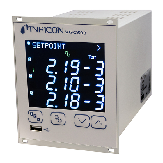
Page 26: Operation
Operation VGC501 4.1 F Front pane Display Operator ke connector VGC502 VGC50 Display Operator ke connecto Display VGC C501 Paramete r or bar graph Set points, para ameter mode, Pressure u unit keylock atus measurem ment channel Measurem ment channel:... - Page 27 Display y VGC502, V VGC503 arameter or bar r graph Meas surement chan nnel 1 Set poin nts, parameter mode, essure unit eylock easurement cha annel 1: Status mea asurement chan nnel 1 easurement val ue in floa ating point or e expo- ntial status Status mea...
-
Page 28: Turning The Vgc50X On And Off
4.2 T Turning th he VGC50x x On and Off Turning the V VGC50x on he power swit tch is on the re ear of the unit urn the VGC5 50x on with the e power switch or centrally, via a a switched p power distribu tor,... - Page 29 VGC50 Ba a rgraph FSR R tina96e1-b (2016-12) C501_VGC502_VGC503.om...
- Page 30 V V GC502, VG G C503 Bargrap ph FSR tina96e1-b (2016-12) VGC501_VGC502_VGC503.o om...
- Page 31 4.4 Meas surement M Mode Measure ement mode i s the standard d operating mo ode of the VG GC50x with dis splay of • a ba ar graph (if req quired) • a me easurement va alue for each measurement t channel •...
- Page 32 Measuremen nt range the unit is ope erated with lin near gauges (C CDG), negativ ve pressures m may be ndicated. Possible cause • negative dr rift • activated of ffset correction Displaying th he gauge First t, select the re equired measu urement chann nel with...
-
Page 33: Parameter Mode
4.5 Param meter Mod The Par rameter mode e is used for di splaying, editi ing and enteri ng parameter values as well a as for testing t the VGC50x a and for saving measuremen nt data. For ea ase of operatio on the individu ual parameters... -
Page 34: Switching Function Parameters
One level back < The VGC501 has two, the VGC502 has four and the VGC503 has six, switching functions with two adjustable thresholds each. The status of the switching functions is displayed on the front panel and can be evaluated via the floating contacts at the CONTROL, respectively RELAY connector. - Page 35 Selec cting a param meter The nam me of the para ameter and the e currently val paramet ter value are d displayed. e.g.: -CH DISAB BLED Switch hing function 1 tur rned off Select p arameter. The e value flashe s and can now w be...
- Page 36 Configuring a switching Value function Configuring a switching function. SP1-CH Switching function 1 is assigned to SP1-CH 1 channel 1 Switching function 1 is assigned to SP1-CH 2 channel 2 (VGC502/503 only) Switching function 1 is assigned to SP1-CH 3 channel 3 (VGC503 only)
- Page 37 Value Limits of the upper switching thresholds The upper switching threshold (Setpoint high) SP1-H defines the pressure at which the switching function is deactivated when the pressure is rising. e.g.: gauge dependent. SP1-H 1500 If another gauge type is connected, the VGC50x automatically adjusts the threshold if required.
-
Page 38: Gauge Parameters
4.5.2 Gauge parameters The sensor parameter group is used for displaying, SENSOR > entering and editing parameters of the connected gauges. Parameters in this group Cleaning the electrode system. DEGAS Measurement range linear gauges. Measurement value filter. FILTER Offset correction. OFFSET Correction factor for other gases. - Page 39 Dega Contam mination depos sits on the elec ctrode system of hot cathod de gauges may y cause instabilit ties of the me asurement va lues. The deg gas function fa acilitates clean ning of the elec ctrode system. The degas s process work ks only at pres ssures below 7...
- Page 40 Measuring range (F.S.) of For linear analog gauges, the full scale (F.S.) value has to be defined on the basis linear gauges of the connected gauge type. For linear digital gauges and logarithmic gauges it is automatically recognized. Available for the following gauges: ...
- Page 41 Measurement value filter The measurement value filter permits a better evaluation of unstable or disturbed measuring signals. The measurement value filter does not affect the analog output (→ 22). Value FILTER No measurement value filter FILTER OFF Fast: FILTER FAST The VGC50x responds quickly to fluctua- tions in the measurement value.
- Page 42 Offset corre ection of the he offset valu e is displayed d and readjuste ed according t to the actual m measurement controller alue. Available for th he following ga auges: Pirani (PSG) Pirani / Cap pacitance (PCG) ...
- Page 43 Zero adjustment of a digital First adjust t the gauge an nd then the co ontroller. Availabl le for the follow wing gauges: Piran (PSG) Piran ni / Capacitan (PCG) Cold d cathode (PEG, M MAG) Cold d cathode / Pir rani (MPG)
- Page 44 Correction factor GAS The correction factor GAS allows • the measured value to be calibrated for the preset gases N , Ar, H , He, Ne, Kr and Xe, or • manual input of the correction factor for other gases (COR). →...
- Page 45 Turning the gauge on / off Activating / deactivating the high vacuum measurement circuit (→ also [31]). Available for the following gauges: Pirani (PSG) Pirani / Capacitance (PCG) Cold cathode (PEG, MAG) Cold cathode / Pirani (MPG) ...
-
Page 46: Gauge Control
Display resolution Display resolution of measured values. Available for the following gauges: Pirani (PSG) Pirani / Capacitance (PCG) Cold cathode (PEG, MAG) Cold cathode / Pirani (MPG) Hot ionization / Pirani (BPG, HPG) Capacitance (CDG) ... - Page 47 Gauge activation Certain gauges can be activated by different means. Value S-ON Manual activation: S-ON HAND The gauge is activated by pressing the key. Hot start: S-ON HOTSTART The gauge is automatically activated when the VGC50x is turned on. Measurement is thus automatically resumed after a power failure.
- Page 48 3 exceeds the switch-off threshold. OFF threshold VGC501 Definition of the OFF threshold for the gauge to be deactivated by itself. This parameter is only available if the sensor deactivation parameter is set to S-OFF SELF.
- Page 49 OFF threshold VGC502, Definition of the OFF threshold for the gauge to be deactivated by a gauge VGC503 connected to the other measurement channel or by itself. This parameter is only available if the sensor deactivation parameter is set to S-OFF CH 1, CH 2, CH 3 (VGC503 only) or S-OFF SELF.
-
Page 50: General Parameters
A change of the pressure unit influences also the pressure unit settings of the BPG, HPG and BCG gauges. VGC501 only: If the measurement unit micron is selected, automatic changeover to Torr occurs above 99000 micron. Below 90 Torr automatic changeover back to the measurement unit micron occurs. - Page 51 Trans smission rate Transm ission rate of t the USB interf face. Value BAUD 9600 baud BAUD USB 9600 19200 bau BAUD USB 19200 38400 bau BAUD USB 38400 57600 bau BAUD USB 57600 115200 ba aud (factory s etting) BAUD USB...
- Page 52 Value AO-MODE Logarithmic representation of the entire AO-MODE LOG measuring range (factory setting). PSG: p = 10^[U/(10 / 7) - 4] PCG: p = 10^[U/(10 / 7) - 4] PEG/MAG: p = 10^[U/(10 / 7) - 9] MPG: p = 10^[U/(10 / 12) - 9] CDG: p = 10^[U/(10 / 4) - 4] ×...
- Page 53 Logarithmic representation matched to the AO-MODE LOG C3 following sensor combination: • CDG on channel 1 • CDG on channel 2 • CDG on channel 3 This characteristic curve is only useful if the sensors have different measuring ranges. The total measuring range of the sensor combination is represented logarithmically in the range 0…10 V.
- Page 54 Error relay Switching behaviour of the error relay. Value ERR-RELAY Switches for all errors (factory setting) ERR-RELAY ALL Only unit errors ERR-RELAY no SE Error sensor 1 and unit error ERR-RELAY CH 1 Error sensor 2 and unit error (VGC502/503 ERR-RELAY CH 2 only) ...
- Page 55 Bar graph In the dot matrix a bar graph or the measured pressure as a function of time (p = f ) may be shown. During parameter setting the parameter and the parameter value may be displayed in place of this. Value BARGRAPH ...
- Page 56 Screensave he screensav ver reduces the e brightness o of the backligh ht or switches it off com- letely (dark ro oom). Value SCREENSAVE fact tory setting SCREE ENSAVE OFF afte er 10 minutes SCREE ENSAVE 10m afte er 30 minutes SCREE ENSAVE 30m...
- Page 57 Measurement value format Measurement values in floating point or exponential format. If a measurement value cannot reasonably be expressed in the floating point format, it is automatically displayed in the exponential format. Value FORMAT Floating point format, if possible FORMAT X.X (factory setting) ...
-
Page 58: Test Parameters
4.5.5 Test Para meters The Test para meter group is s used for e.g . displaying TEST > the firmware v version, enterin ng and editing g special para- meter values, and for runnin ng test program group is only available if th key was s pressed whil... - Page 59 After the e test, FLASH ERR an 8-digit checksum (e.g. ) is disp played. ASH 0x1234 5678 If the error r persists afte r repeating the e test, please con ntact your nea arest INFICON service ce enter. tina96e1-b (2016-12) C501_VGC502_VGC503.om...
- Page 60 CO ONTROL conn nector VGC501) or to o the RELAY c connector (VG GC502/503) on n the rear of th he unit (→ → 22). Chec...
-
Page 61: Data Logger Mode
Not all USB memory sticks are automatically recognized by the VGC50x, as they (in particular cheaper brands) do not always conform to USB standard requirements. Try a different memory stick before contacting your nearest INFICON service center. Parameters in this group Current date... - Page 62 Decimal se parator Decimal separa ator for measu urement value es in the meas surement data file. Wert DEC-SEPARA ATOR Dec cimal comma DEC-S SEPARATOR Dec cimal point DEC-S SEPARATOR Value File name Name o of the measur rement data fil e, max.
-
Page 63: Parameter Transfer Mode
4.5.7 Parameter Transfer Mode This group is used for SETUP > • saving all parameters on a USB memory stick (interface type A on the front of the VGC50x) • loading all parameters from a USB memory stick onto the VGC50x •... - Page 64 Loading pa rameters oading all par rameters from a USB memo ory stick onto t the VGC50x. If no o unit has been n specified for r the setpoint/t threshold and offset values in th he CSV-file, th e value is read d in mBar or h hPa, respectiv vely.
-
Page 65: Communication Protocol (Serial Interface)
(→ 70). Communication structure and procedures are identical for the three controllers VGC501, VGC502 and VGC503. Therefore the term VGC50x is used in this chapter. It should be noted that mnemonics with channel specific parameters must be issued with the number of values corresponding to the number of channels of the respective device. -
Page 66: Data Transmission
5.1 Data Transmission The data transmission is bi-directional, i.e. data and control commands can be transmitted in either direction. Data format 1 start bit, 8 data bits, no parity bit, 1 stop bit, no hardware handshake. Definitions The following abbreviations and symbols are used: Symbol Meaning HOST... -
Page 67: Communication Protocol
5.2 Communication Protocol Transmission format Messages are transmitted to the VGC50x as ASCII strings in the form of mnemonic operating codes and parameters. All mnemonics comprise three ASCII characters. Spaces are ignored. <ETX> (CTRL C) clears the input buffer in the VGC50x. Transmission protocol HOST VGC50x... -
Page 68: Mnemonics
Start / stop data logger Language (display) Keylock Ethernet MAC address Offset correction (linear gauges) Offset display (linear gauges) Offset correction (VGC501 only) Firmware version Measurement data gauge 1 Measurement data gauge 2 Measurement data gauge 3 Pirani range extension... - Page 69 Reset Operating hours RS232C test Save parameters (EEPROM) Gauge 1 control Gauge 2 control Gauge 3 control Save / load parameters (USB) Switching function 1 Switching function 2 Switching function 3 Switching function 4 Switching function 5 Switching function 6 Switching function status A/D converter test ID resistance test...
-
Page 70: Measurement Mode
5.4 Measurement Mode - Continuous output of Transmit: [,a] <CR>[<LF>] measurement values Description Time interval, a = 0 –> 100 ms 1 –> 1 s (default) 2 –> 1 minute Receive: <ACK><CR><LF> <ACK> is immediately followed by the continuous output of the measurement value in the desired interval. - Page 71 - Combined pressure This parameter combines different pressure ranges to one combined pressure range (linear gauges) range, if several linear gauges with different full scales (F.S.) are connected to the VGC502 and VGC503. Thus the pressure for this combined pressure range can be read out with best accuracy.
- Page 72 - Error status Transmit: <CR>[<LF>] Error status Receive: <ACK><CR><LF> Transmit: <ENQ> Receive: aaaa <CR><LF> Description aaaa Error status, aaaa = 0000 –> No error 1000 –> ERROR (controller error (see display on front panel) 0100 –> NO HWR (no hardware) 0010 –>...
- Page 73 - Measurement data Transmit: <CR>[<LF>] gauge 1, 2 and 3 Receive: <ACK><CR><LF> Transmit: <ENQ> Receive: a,sx.xxxxEsxx,b,sy.yyyyEsyy,c,sz.zzzzEszz <CR><LF> Description Status gauge 1, a = 0 –> Measurement data okay 1 –> Underrange 2 –> Overrange 3 –> Sensor error 4 –> Sensor off (PEG, MAG) 5 –>...
- Page 74 - Reset Transmit: [,a] <CR>[<LF>] Description 1 –> Cancels currently active error and re- turns to measurement mode Receive: <ACK><CR><LF> Transmit: <ENQ> Receive: b[,b][,b][…] <CR><LF> Description List of all present error messages, b = 0 –> No error 1 –> Watchdog has responded 2 –>...
- Page 75 - Gauge identification Transmit: <CR>[<LF>] Gauge identification Receive: <ACK><CR><LF> Transmit: <ENQ> Receive: a,b,c <CR><LF> Description Identification gauge 1, a = (Pirani Gauge) (Pirani / Capacitance Gauge) PEG/MAG (Cold Cathode Gauge) (Cold Cathode / Pirani Gauge) (Capacitance Gauge) (Hot Ionization / Pirani Gauge) BPG402 (Hot Ionization / Pirani Gauge) (Hot Ionization / Pirani Gauge)
-
Page 76: Switching Function Parameters
5.5 Switching Function Parameters - Switching function status Transmit: <CR>[<LF>] Receive: <ACK><CR><LF> Transmit: <ENQ> Receive: a,b,c,d,e,f <CR><LF> Description Status switching function 1, a = 0 –> Off 1 –> On Status switching function 2 Status switching function 3 Status switching function 4 Status switching function 5 Status switching function 6 SP1 …... -
Page 77: Gauge Parameters
5.6 Gauge Parameters - Calibration factor corresponds to the COR command CF1, CF2, CF3 - Calibration Transmit: [,a.aaa] <CR>[<LF>] factor gauge 1, 2 or 3 Description Calibration factor gauge x = 1 –> Gauge 1 2 –> Gauge 2 3 –> Gauge 3 a.aaa Calibration factor gauge x, 0.100 …... - Page 78 - Display resolution Transmit: [,a,a,a] <CR>[<LF>] Receive: <ACK><CR><LF> Transmit: <ENQ> Receive: a,a,a <CR><LF> Description Resolution a = 0 –> AUTO (default) 1 –> One digit 2 –> Two digits 3 –> Three digits 4 –> Four digits When the PrE (→ 90) is ON and the pressure is in the range p<1.0E-4 mbar the display resolution of the PSG- and PCG gauges is reduced by one decimal digit.
- Page 79 - Measurement value filter Transmit: [,a,b,c] <CR>[<LF>] Description Filter gauge 1, a = 0 –> Filter off 1 –> Fast 2 –> Normal 3 –> Slow Filter gauge 2 Filter gauge 3 Receive: <ACK><CR><LF> Transmit: <ENQ> Receive: a,b,c <CR><LF> Description Filter time constant gauge 1 Filter time constant gauge 2 Filter time constant gauge 3...
- Page 80 - Measurement range The full scale value of the measurement range (Full Scale) of linear (linear gauges) analog gauges has to be defined by the user. The full scale value of linear digital gauges and logarithmic gauges is automatically recognized. Transmit: [,a,b,c] <CR>[<LF>] Description...
- Page 81 - Gas type correction Transmit: [,a,b,c] <CR>[<LF>] Receive: <ACK><CR><LF> Transmit: <ENQ> Receive: a,b,c <CR><LF> Description Gas type correction measurement channel 1, a = 0 –> nitrogen / air (default) 1 –> Argon 2 –> Hydrogen 3 –> Helium 4 –> Neon 5 –>...
- Page 82 - Offset correction Transmit: [,a,b,c] <CR>[<LF>] (linear gauges) Description Offset correction gauge 1, a = 0 –> Off (default) 1 –> On 2 –> Determine offset value and activate offset correction 3 –> Adjust the zero of linear gauge Offset correction gauge 2 Offset correction gauge 3 Receive: <ACK><CR><LF>...
- Page 83 - Offset correction Transmit: [,a,sx.xxxxEsxx] <CR>[<LF>] (linear gauges, VGC501 only) Description Mode, a = 0 –> Off (default) No offset value needs to be entered 1 –> On If no offset value has been entered, the pre- viously defined offset value is taken over 2 –>...
-
Page 84: Gauge Control
5.7 Gauge Control SC1, SC2, - Gauge 1, 2 or Transmit: [,a,b,c.ccEscc,d.ddEsdd] <CR>[<LF>] 3 control Description Controlled gauge, x = 1 –> Gauge 1 2 –> Gauge 2 3 –> Gauge 3 Gauge activation, a = 0 –> Manual (default) 1 –>... -
Page 85: General Parameters
5.8 General Parameters - Analog output mode Characteristic curve of the recorder output Transmit: [,a,b] <CR>[<LF>] Description Measurement channel, a = 0 –> Measurement channel 1 1 –> Measurement channel 2 2 –> Measurement channel 3 Output characteristic, b = 0 –>... - Page 86 - Backlight Transmit: [,a] <CR>[<LF>] Description Backlight in percent, a = 0 … 100 100% is full brightness Receive: <ACK><CR><LF> Transmit: <ENQ> Receive: a <CR><LF> Description Backlight - Transmission rate (USB) Transmit: [,a] <CR>[<LF>] Description Transmission rate, a = 0 –> 9600 Baud 1 –>...
- Page 87 - Display control bar graph Transmit: [,a,b] <CR>[<LF>] Description Measurement channel, a = 0 –> Measurement channel 1 1 –> Measurement channel 2 2 –> Measurement channel 3 Bar graph display, b = 0 –> Off (default) 1 –> Bar graph covering full scale range 2 –>...
- Page 88 - Display control contrast Transmit: [,a] <CR>[<LF>] Description Contrast in percent, a = 0 … 100 100% = full contrast Receive: <ACK><CR><LF> Transmit: <ENQ> Receive: a <CR><LF> Description Contrast - Display control Transmit: [,a] <CR>[<LF>] screensaver Description Screensaver, a = 0 –>...
- Page 89 - Measurement range end Transmit: [,a] <CR>[<LF>] value Description Measurement range end value, a = 0 –> UR or OR is displayed (default) when an underrange or overrange occurs 1 –> The measurement range end value is displayed when an underrange or overrange occurs Receive: <ACK><CR><LF>...
- Page 90 - Pirani range extension Transmit: [,a] <CR>[<LF>] Description Pirani range extension, a = 0 –> Disabled (default) 1 –> Enabled Receive: <ACK><CR><LF> Transmit: <ENQ> Receive: a <CR><LF> Description Pirani range extension status PCG and PSG gauges only, measurement range up to 5×10 mbar.
-
Page 91: Data Logger Parameters
5.9 Data Logger Parameters The group is only available when a USB memory stick formatted for the the FAT file system (FAT32) is plugged in. Use a max. 32 GB memory stick. - Date Transmit: [,yyyy-mm-dd] <CR>[<LF>] Receive: <ACK><CR><LF> Transmit: <ENQ>... -
Page 92: Parameter Transfer
Receive: <ACK><CR><LF> Transmit: <ENQ> Receive: a <CR><LF> Description 0 –> INFICON gauges (standard) 1 –> OLV transmitter - Display test corresponds to the TDI command - EEPROM test corresponds to the TEE command - FLASH test corresponds to the TEP command... - Page 93 - Hardware version Transmit: <CR>[<LF>] Receive: <ACK><CR><LF> Transmit: <ENQ> Receive: a.a <CR><LF> Description Hardware version, e.g. 1.0 - I/O test corresponds to the TIO command - Keylock Transmit: [,a] <CR>[<LF>] Description Keylock, a = 0 –> Off (default) 1 –> On Receive: <ACK><CR><LF>...
- Page 94 - Operating hours corresponds to the TRS command - A/D converter test Transmit: <CR>[<LF>] Receive: <ACK><CR><LF> Transmit: <ENQ> Receive: aa.aaaa,bb.bbbb,cc.cccc <CR><LF> Description aa.aaaa A/D converter channel 1 Measurement signal [0.0000 … 11.0000 V] bb.bbbb A/D converter channel 2 Measurement signal [0.0000 … 11.0000 V] cc.cccc A/D converter channel 3 Measurement signal [0.0000 …...
- Page 95 - FLASH test Test of the program memory. Transmit: <CR>[<LF>] Receive: <ACK><CR><LF> Transmit: <ENQ> Starts the test (very brief) Receive: aaaa,bbbbbbbb <CR><LF> Description aaaa Error word bbbbbbbbbb Check sum (hex) - I/O test Caution Caution: The relays switch irrespective of the pressure. Starting a test program may cause unwanted effects in connected control systems.
- Page 96 - Operator key test Transmit: <CR>[<LF>] Receive: <ACK><CR><LF> Transmit: <ENQ> Receive: abcd <CR><LF> Description Key 1, a = 0 –> Not pushed 1 –> Pushed Key 2, b = 0 –> Not pushed 1 –> Pushed Key 3, c = 0 –>...
-
Page 97: Further
- Watchdog control Transmit: [,a] <CR>[<LF>] Description Watchdog control, a = 0 –> Manual error acknowledgement 1 –> Automatic error acknowledgement (default) If the watchdog has responded, the error is automatically acknowl- edged and cancelled after 2 s. Receive: <ACK><CR><LF> Transmit: <ENQ>... -
Page 98: Example
5.13 Example "Transmit (T)" and "Receive (R)" are related to host. Request for gauge identification <CR> [<LF>] Positive acknowledgement R: <ACK> <CR> <LF> Request for data transmission T: <ENQ> Gauge identification R: PSG <CR> <LF> Request for parameters of switching function 1 <CR>... -
Page 99: Maintenance
6 Maint tenance Cleanin g the VGC50 For clea aning the outs ide of the unit a slightly moi ist cloth will us sually do. Do n not use any agg gressive or sco ouring cleanin g agents. DANGER DANGER R: mains voltag Contact w with live parts i... -
Page 100: Troubleshooting
roublesh hooting gnalization o of errors he error is sho own in the dot t matrix and th he error relay o opens (→ 2 22). rror message Possible caus se and remedy y/acknowledg ement Interruption o r instability in sensor line or r connector SENSOR ERR... -
Page 101: Repair
8 Repair Return defective products to your nearest INFICON service center for repair. INFICON assumes no liability and the warranty is rendered null and void if repair work is carried out by the end-user or by third parties. 9 Accessories... -
Page 102: Appendix
Appendix ConversionTables Weights slug 2.205 68.522×10 35.274 0.454 31.081×10 slug 14.594 32.174 514.785 28.349×10 62.5×10 1.943×10 Pressures , Pa mBar, hPa Torr , Pa 10×10 10×10 7.5×10 9.869×10 100×10 750.062 0.987 mBar, hPa 750.062×10 0.987×10 Torr 133.322 1.333×10 1.333 1.316×10 101.325×10 1.013 1.013×10... -
Page 103: B: Firmware Update
Firmware Update If your VGC50x firmware needs updating, e.g. for implementing a new gauge type, please contact your nearest INFICON service center. A firmware update is possible • via a USB memory stick (type A connector on the front of the unit), or •... - Page 104 Start USB UpdateTool, select the COM interface from the menu and click on <Connect>. Successfully connected Click on <Release Notes> to view the software release notes. tina96e1-b (2016-12) VGC501_VGC502_VGC503.om...
- Page 105 … • • Option <Lo oad from disk> >: Download a a copy of the f irmware from website "w www.inficon.co m". Then, sele ect the approp priate folder. • • Option <Lo oad from serve er>: The upda...
-
Page 106: C: Ethernet Configuration
Ethernet Configuration The user program (e.g. terminal program, LabView, etc.) must support serial inter- faces. Under Microsoft Windows operating systems the VGC50x is listed as a virtual COM interface. Please contact your network administrator, before starting Ethernet configuration. Your operating system should be updated first. Additionally administra- tor rights are required. -
Page 107: C 2: Connect The Vgc50X To A Computer
C 2: Connect the VGC50x to a Computer Computer with DHCP server Connect the VGC50x to a computer … • with a crossover Ethernet cable, • via a switch, or • with an Ethernet patch cable (precondition: the interface is auto MDI-X capable). - Page 108 Download the Ethernet Configuration Tool from the CD ROM or from our website "www.inficon.com". Start the Ethernet Configuration Tool and click on <Search Devices>: The tool searches the local network for connected devices and lists the devices thus found in the selection window. The <Device Info> register shows basic information about the selected device.
- Page 109 In the <Virtual Serial Port> register a specific COM Port can be assigned to each device, and/or … … a new COM Port can be created. The new created virtual interface (COM) appears in the list box and in the Windows Device Manager. tina96e1-b (2016-12) VGC501_VGC502_VGC503.om...
-
Page 110: D: Literature
Literature [1] www.inficon.com Operating Manual Pirani Standard Gauge PSG400, PSG400-S tina04e1 INFICON AG, LI–9496 Balzers, Liechtenstein [2] www.inficon.com Operating Manual Compact Pirani Gauge PSG500/-S, PSG502-S, PSG510-S, PSG512-S tina44e1 INFICON AG, LI–9496 Balzers, Liechtenstein [3] www.inficon.com Operating Manual... - Page 111 [13] www.inficon.com Operating Manual High Pressure / Pirani Gauge HPG400 tina31e1 INFICON AG, LI–9496 Balzers, Liechtenstein [14] www.inficon.com Operating Manual TripleGauge™ BCG450 tina40e1 INFICON AG, LI–9496 Balzers, Liechtenstein [15] www.inficon.com Operating Manual Inverted Magnetron Pirani Gauge MPG400, MPG401 tina48e1 INFICON AG, LI–9496 Balzers, Liechtenstein...
-
Page 112: Etl Certification
Capacitance Diaphragm Gauge CDG160D, CDG200D tina53e1 INFICON AG, LI–9496 Balzers, Liechtenstein ETL Certification ETL LISTED The products VGC501, VGC502 and VGC503 • conform to the UL Standards UL 61010-1 and UL 61010-2-030 • are certified to the CSA Standards CSA C22.2 # 61010-1 and CSA C22.2 # 61010-2-030... -
Page 113: Eu Declaration Of Conformity
EU Declaration of Conformity We, INFICON, hereby declare that the equipment mentioned below complies with the provisions of the Directive relating to electrical equipment designed for use within certain voltage limits 2014/35/EU, the Directive relating to electromagnetic compatibility 2014/30/EU and the Directive on the restriction of the use of certain hazardous substances in electrical and electronic equipment 2011/65/EU. - Page 114 Notes tina96e1-b (2016-12) VGC501_VGC502_VGC503.om...
- Page 115 Notes tina96e1-b (2016-12) VGC501_VGC502_VGC503.om...
- Page 116 LI–9496 Balzers Liechtenstein Tel +423 / 388 3111 Fax +423 / 388 3700 reachus@inficon.com Original: German tina96d1-b (2016-12) www.inficon.com t i na96e1- b...
Need help?
Do you have a question about the VGC501 and is the answer not in the manual?
Questions and answers