
Subscribe to Our Youtube Channel
Related Manuals for Inficon TPG36 Series


Summary of Contents for Inficon TPG36 Series
-
Page 1: Cf1 Calibration Factor Gauge
Operating M Manual Incl. EU Declara ation of Conform mity Singl e-Cha annel l & Tw wo-Ch hanne e l Con n trol U U nits for Co ompa act Ga auges TPG361 1, TPG3 IG 3500 BEN 2016-07) -
Page 2: Product Identification
Produ uct Identif fication n all communic cations with IN NFICON, plea se specify the e information o on the product ameplate. Specim men nameplate Valid his document t applies to pro oducts with pa art numbers: IGD2 28040 (TPG361) IGD2 28290 (TPG362) -
Page 3: Table Of Contents
Contents Product Identification Validity Intended Use Scope of Delivery 1 Safety 1.1 Symbols Used 1.2 Personnel Qualifications 1.3 General Safety Instructions 1.4 Liability and Warranty 2 Technical Data 3 Installation 3.1 Personnel 3.2 Installation, Setup 3.2.1 Rack Installation 3.2.2 Installation in a control panel 3.2.3 Use as Desk-Top Unit 3.3 Mains Power Connector 3.4 Gauge Connectors sensor 1, sensor 2... - Page 4 5.7 Gauge Control 5.7.1 SC1, SC2 - Gauge 1 and 2 Control 5.8 General Parameters 5.8.1 - Backlight 5.8.2 - Transmission Rate (USB) 5.8.3 - Display Control Bar Graph 5.8.4 - Display Control Contrast 5.8.5 - Display Control Screensave 5.8.6 - Error Relay Allocation 5.8.7 - Measurement Range End Value...
-
Page 5: Safety
1 Safety 1.1 Symbols Used Symbols for residual risks DANGER Information on preventing any kind of physical injury. WARNING Information on preventing extensive equipment and environmental damage. Caution Information on correct handling or use. Disregard can lead to malfunctions or minor equipment damage. -
Page 6: General Safety Instructions
1.3 G General Sa afety Adhere to the a applicable reg ulations and t ake the neces ssary precauti ons for all work you are g oing to do and d consider the e safety instruc ctions in this d document. -
Page 7: Technical Data
2 Technical Data Mains specifications Voltage 100 … 240 VAC ±10% Frequency 50 … 60 Hz Power consumption TPG361 ≤45 VA TPG362 ≤65 VA Overvoltage category Protection class Connection European appliance connector IEC 320 C14 Ambience Temperature storage –20 … +60 °C operation + 5 …... - Page 8 Measurement values Measurement ranges depending on gauges (→ [1] … [18]) Measurement error gain error ≤0.01% F.S. (typical) ≤0.10% F.S. (over temperature range, time) offset error ≤0.01% F.S. (typical) ≤0.10% F.S. (over temperature range, time) Measurement rate analog ≥100 / s Display rate ≥10 / s Filter time constant...
- Page 9 Gauge control Automatic ON setpoint adjustable (→ 36) OFF setpoint adjustable (→ 37) Manual via keys activation/deactivation → 22 External via control connector ON condition Signal ≤+0.8 V (dc) OFF condition Signal +2.0 … 5 V (dc) or input open Hotstart when mains power on →...
- Page 10 imensions [m or incorporatio on into a rack or control pan nel or as a des sk-top unit Weight .1 kg IG 3500 BEN 016-07) TPG361, TPG362.o om...
-
Page 11: Installation
3 Instal llation 3.1 Perso onnel killed perso nnel The unit m may only be in nstalled by per rsons who hav ve suitable tec chnical training an nd the necess sary experienc ce or who have e been instruc cted by the end-u ser of the prod... -
Page 12: Installation In A Control Panel
Height 3 rac ck chassis a dapter Secure the rack adap pter in the rack k frame. The maximum m admissible a mbient tempe erature (→ 7 7) must not be exceeded and the air circula ation must not t be obstructed ... -
Page 13: Use As Desk-Top Unit
For redu ucing the mec chanical strain on the front p panel of the TP PG36x, prefer rably support the unit. Slide the TPG 36x into the c ut-out of the c control panel … … … … and secure it t with four M3 or equivalent screws. -
Page 14: Mains Power Connector
3.3 M Mains Pow wer Conne ector DANG NGER: line vo oltage Inco orrectly groun ded products can be extrem mely hazardou us in the ent of a fault. e only a 3-con nductor power cable with pro otective groun nd. -
Page 15: Control Connector
Pin ass signment Gauge con nnector senso r 2 is not pres sent in TPG36 sensor r 1, sensor 2 Pin assi ignment of the e two female 6 6-pin Amphen nol C91B appl liance connec tors: Signal Identificatio Supply +24 V (dc) Supply com... -
Page 16: Relay Connector
3.6 R Relay Con nnector his connector r allows to use e of the floating g switching co ontacts for an external ontrol system. nect the perip pheral compon nents to the re elay connector r on the rear o the u unit using you r own, screen... -
Page 17: Interface Connector Rs485
3.7 Interf face Conn nector The RS4 485 interface allows for ope erating the TP PG36x via a HO OST or termin RS48 (→ 51 Connect th he serial interfa ace to the RS S485 connecto or on the rear o of the unit using a a screened (e... -
Page 18: Interface Connector Ethernet
Pin assignme USB Type A Pin assignmen t of the 4-pin U USB Type A ppliance conn nector: Signa VBUS S (5 V) 3.10 Interface e Connecto he ethernet in nterface allows s direct comm unication with h the TPG36x via a com- uter. -
Page 19: Operation
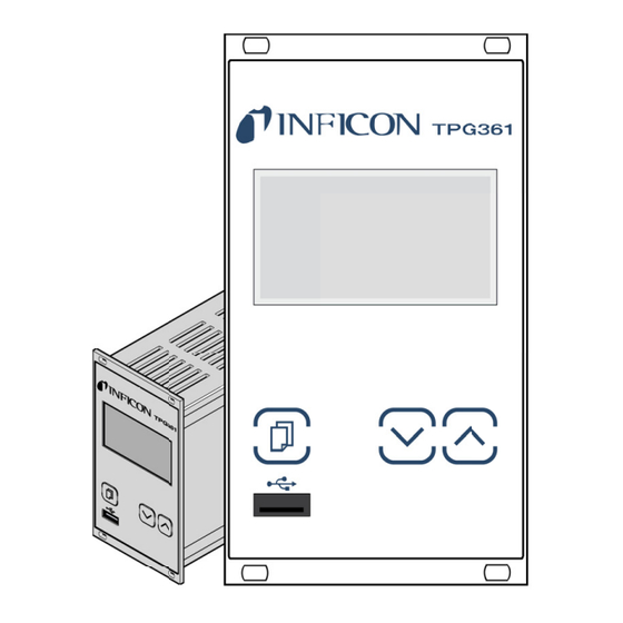
4 Operation 4.1 Front panel TPG361 TPG362 Display Operator keys connector Display TPG36x Parameter or bar graph Schaltpunkte, Parametermenü, Set points, parameter mode, Pressure unit or voltage Eingabesperre keylock Status measurement channel 1 Measurement channel 1: Measurement value in floating point or expo- nential status Status measurement channel 2 Measurement channel 2:... -
Page 20: Turning The Tpg36X On And Off
Bar graph with set point mea asurement cha annel 1 Measurement c channel 2 Pressure vs. tim me, trend mea asurement cha annel 1 Measurement c channel 2 Set points s, parameter mode, Set points 1 … Parameter mod de activated keylock Relay on Relay... -
Page 21: Operating Modes
The TPG36x works in the following operating modes: 4.3 Operating Modes • Measurement mode for displaying measurement values or statuses (→ 22) • Parameter mode for displaying and editing parameters (→ 24) − Switching function parameter group SETPOINT >... -
Page 22: Measurement Mode
4.4 Measurement Mode Measurement mode is the standard operating mode of the TPG36x with display of • a bar graph (if required) • a measurement value for each measurement channel • status messages for each measurement channel Adjusting bar graph If required a bar graph may be displayed (→... - Page 23 Measurement range If the unit is operated with linear gauges (CMR261 … 375, APR250 … 267), negative pressures may be indicated. Possible causes: • negative drift • activated offset correction. Displaying the gauge Press keys for >0.5 … 1 s: identification For the measurement channel in question the type of the connected gauge is automatically identified and...
-
Page 24: Parameter Mode
4.5 Parameter Mode The Parameter mode is used for displaying, editing and entering parameter values as well as for testing the TPG36x and for saving measurement data. For ease of operation the individual parameters are divided into groups. Unit switches from measurement mode to para- meter mode. -
Page 25: Switching Function Parameters
4.5.1 Switching Function The switching function parameter groupis used for dis- SETPOINT > Parameters playing, editing and entering threshold values and as- signing the two (TPG361) or four (TPG362) switching functions to a measurement channel. Parameters in this group Assignment of switching function 1 to a channel SP1-CH Switching function 1 lower threshold SP1-L... - Page 26 Selecting a parameter The name of the parameter and the currently valid parameter value are displayed. e.g.: SP1-CH DISABLED Switching function 1 turned off Select parameter. The value flashes and can now be edited. Editing and saving the ...
-
Page 27: Gauge Parameters
-4 *) 5×10 1500 Sx TPR/PCR IKR2x1: 1×10 IKR36x: 1×10 1×10 Sx IKR IKR270: 1×10 1×10 1000 Sx PKR 1×10 1000 Sx IMR 5×10 1000 Sx PBR F.S. / 1000 Sx CMR/APR all values in mbar, GAS=nitrogen 5×10 mbar, if RNE-EXT is activated (→ 39) The minimum hysteresis between the upper and lower switching threshold amounts to at least 10% of the lower threshold or 1% of the set full scale value. - Page 28 Parameters in this group Cleaning the electrode system. DEGAS Measurement range linear gauges. Measurement value filter. FILTER Offset correction. OFFSET Calibration factor for other gases. Offset correction. Display resolution. DIGITS One level back. < Selecting a parameter The name of the parameter and the currently valid parameter value are displayed.
- Page 29 Value DEGAS Normal operation (Degas blocked) DEGAS OFF Degas: The electron collection grid is DEGAS ON heated to ≈700 °C by electron bombardment and the electrode system is thus cleaned. Duration = 180 s. Editing and saving a ...
- Page 30 Measurement value filter The measurement value filter permits a better evaluation of unstable or disturbed measuring signals. The measurement value filter does not affect the analog output (→ 15). Value FILTER No measurement value filter FILTER OFF Fast: FILTER FAST The TPG36x responds quickly to fluctua- tions in the measurement value.
- Page 31 Offset correction The offset value is displayed and readjusted according to the actual measurement value. Available for the following gauges: Pirani & Pirani Capacitance Gauge (TPR/PCR) Cold Cathode Gauge (IKR) ® FullRange CC Gauge (PKR) Process Ion Gauge (IMR) ®...
- Page 32 Calibration factor GAS The calibration factor GAS allows • the measured value to be calibrated for the preset gases N , Ar, H , He, Ne, Kr and Xe, or • manual input of the correction factor for other gases (COR). →...
- Page 33 Display resolution Display resolution of measured values. Available for the following gauges: Pirani & Pirani Capacitance Gauge (TPR/PCR) Cold Cathode Gauge (IKR) ® FullRange CC Gauge (PKR) Process Ion Gauge (IMR) ® FullRange BA Gauge (PBR) ...
-
Page 34: Gauge Control
4.5.3 Gauge Control The sensor control group is used for displaying, enter- SENSOR-CONTROL > ing and editing parameters which define how the con- nected gauges are activated / deactivated. If the connected gauges cannot be controlled (→ 35), this group is not available. - Page 35 Certain gauges can be activated by different means. Gauge activation The following gauges can be controlled: Pirani & Pirani Capacitance Gauge (TPR/PCR) Cold Cathode Gauge (IKR) ® FullRange CC Gauge (PKR) Process Ion Gauge (IMR) ® ...
- Page 36 Definition of the ON threshold for the gauge to be activated by a gauge connected ON threshold to the other measurement channel. (TPG362 only) Available for the following following gauges: Pirani & Pirani Capacitance Gauge (TPR/PCR) Cold Cathode Gauge (IKR) ®...
- Page 37 only for gauges with 1, 10 or 100 mbar F.S. Automatic deactivation: S-OFF CH 2 The gauge is deactivated by one of the (only TPG362) following gauges connected to measurement channel 2: Pirani & Pirani Capacitance Gauge (TPR/PCR) ...
-
Page 38: General Parameters
4.5.4 General Parameters The General parameters group is used for displaying, GENERAL > entering and editing generally applicable system para- meters. Parameters in this group Measurement unit UNIT Transmission rate USB interface BAUD USB Pirani range extension RNG-EXT Error relay ERR-RELAY Penning underrange PE-UR... - Page 39 Transmission rate Transmission rate of the USB interface. The transmission rate of the RS485 interface is 9600 baud and cannot be changed. Value BAUD USB 9600 baud (factory setting) BAUD USB 9600 19200 baud BAUD USB 19200 38400 baud BAUD USB 38400 ...
- Page 40 Underrange control Definition of behaviour in the event of an underrange with Cold Cathode Gauges (Penning underrange control). Available for the following gauges: Pirani & Pirani Capacitance Gauge (TPR/PCR) Cold Cathode Gauge (IKR) ® FullRange CC Gauge (PKR) ...
- Page 41 Bar graph In the dot matrix a bar graph or the measured pressure as a function of time (p = f ) may be shown. During parameter setting the parameter and the parameter value may be displayed in place of this. Value BARGRAPH ...
- Page 42 Backlight Value BACKLIGHT e.g. Factory setting BACKLIGHT 60% Adjustable from 0 … 100% 100% = full brightness Screensave Value SCREENSAVE factory setting SCREENSAVE OFF after 10 minutes SCREENSAVE 10min after 30 minutes SCREENSAVE 30min after 1 hour SCREENSAVE 1h ...
- Page 43 Measurement value format Measurement values in floating point or exponential format. If a measurement value cannot reasonably be expressed in the floating point format, it is automatically displayed in the exponential format. Value FORMAT Floating point format, if possible FORMAT X.X (factory setting) ...
-
Page 44: Test Parameters
The parameters in this group are available for all gauges. Firmware version The firmware version (program version) is displayed. Version e.g. This information is helpful when contacting SOFTWARE 1.00 INFICON Hardware version The hardware version is displayed. Hardware e.g. This information is helpful when contacting HARDWARE 1.0... - Page 45 Test completed, error found. After the test, FLASH ERROR an 8-digit checksum (e.g. FLASH ) is displayed. 0x12345678 If the error persists after repeating the test, please contact your nearest INFICON ser- vice center. IG 3500 BEN (2016-07) TPG361, TPG362.om...
- Page 46 Test completed, no error found. EEPROM PASS Test completed, error found. EEPROM ERROR If the error persists after repeating the test, please contact your nearest INFICON ser- vice center. Display test Test of the display. Test sequence Press keys at the same time to start test DISPLAY +...
-
Page 47: Data Logger Mode
Not all USB memory sticks are automatically recognized by the TPG36x, as they (in particular cheaper brands) do not always conform to USB standard requirements. Try a different memory stick before contacting your nearest INFICON service center. IG 3500 BEN (2016-07) - Page 48 Parameters in this group Current date DATE Current time TIME Recording interval INTERVAL Decimal separator DEC-SEPARATOR File name FILENAME Start / stop display START / STOP Deletion of files with displayed measurement data CLEAR Value Date Current date in the format YYYY-MM-DD DATE e.g.
-
Page 49: Setup Mode
Starting / stopping measurement value record. Start / Stop The number of the respective measurement channel ( , ) flashes during measurement data record. Value START START Press key to start data record: Data record is running, display has changed to and the down arrow is blink- STOP ... - Page 50 Saving a parameter Saving all parameters of the TPG36x to a USB memory stick (file ending: CSV). Value SAVE File name on the USB memory stick: SAVE SETUP SETUP01.CSV File name on the USB memory stick: SAVE SETUP99 SETUP99.CSV ...
-
Page 51: Communication Protocol (Serial Interface)
5 Communication Protocol (Serial Interface) The serial interface is used for communication between the TPG36x and a com- puter. A terminal can be connected for test purposes. When the TPG36x is put into operation, it starts transmitting measured values in intervals of 1 s. -
Page 52: Communication Protocol
5.2 Communication Protocol Transmission format Messages are transmitted to the TPG36x as ASCII strings in the form of mnemonic operating codes and parameters. All mnemonics comprise three ASCII characters. Spaces are ignored. <ETX> (CTRL C) clears the input buffer in the TPG36x. HOST TPG36x Explanation... -
Page 53: Mnemonics
5.3 Mnemonics → A/D converter test Are you there? Backlight Transmission rate (USB) Calibration factor Calibration factor gauge 1 Calibration factor gauge 2 Continuous mode of measurement values Combined pressure (linear gauges) Date Display control bar graph Display control contrast Display resolution Display control screensave Degas... -
Page 54: Measurement Mode
Switching function 1 Switching function 2 Switching function 3 Switching function 4 Switching function status Test A/D converter, ID resistance Gauge identification Time Operator key test Torr lock Inner temperature of the unit Pressure unit Watchdog control 5.4 Measurement Mode 5.4.1 - Continuous Transmit:... -
Page 55: Cpr - Combined Pressure Range (Linear Gauges, Tpg362 Only)
5.4.2 - Combined This command combines different pressure ranges to one combined pressure pressure range (linear range, if several linear gauges with different full scales (F.S.) are connected to the TPG362. Thus the pressure for this combined pressure range can be read out with gauges, best accuracy. -
Page 56: Err - Error Status
5.4.3 - Error Status Transmit: <CR>[<LF>] Error status Receive: <ACK><CR><LF> Transmit: <ENQ> Receive: aaaa <CR><LF> Description aaaa Error status, aaaa = 0000 –> No error 1000 –> ERROR (controller error (see display on front panel) 0100 –> NO HWR (no hardware) 0010 –>... -
Page 57: Prx - Measurement Data Gauges 1 And
5.4.5 - Measurement Data Transmit: <CR>[<LF>] Gauges 1 and 2 Receive: <ACK><CR><LF> Transmit: <ENQ> Receive: a,sx.xxxxEsxx,b,sy.yyyyEsyy <CR><LF> Description Status gauge 1, a = 0 –> Measurement data okay 1 –> Underrange 2 –> Overrange 3 –> Sensor error 4 –> Sensor off (IKR, PKR, IMR, PBR) 5 –>... -
Page 58: Sen - Gauge On/Off
Description (TPG362 only) List of all present error messages, b = 0 –> No error 1 –> Watchdog has responded 2 –> Task fail error 3 –> FLASH error 4 –> RAM error 5 –> EEPROM error 6 –> DISPLAY error 7 –>... -
Page 59: Switching Function Parameters
5.5 Switching Function Parameters 5.5.1 - Switching Function Transmit: <CR>[<LF>] Status Receive: <ACK><CR><LF> Transmit: <ENQ> Receive: a,b,c,d <CR><LF> Description Status switching function 1, a = 0 –> Off 1 –> On Status switching function 2 Status switching function 3 Status switching function 4 5.5.2 SP1 …... -
Page 60: Gauge Parameters
5.6 Gauge Parameters 5.6.1 - Calibration Factor Precondition: Parameter "GAS" is set to "7" (other gases) (→ 62). Except linear gauges. This parameter is effective in the entire measurement range of the gauge. Transmit: [,a.aaa,b.bbb] <CR>[<LF>] Description a.aaa Calibration factor gauge 1, 0.100 … 10.000 (default = 1.000) b.bbb Calibration factor gauge 2... -
Page 61: Dgs - Degas
5.6.4 - Degas Transmit: [,a,b] <CR>[<LF>] Description Degas gauge 1, a = 0 –> Degas off (default) 1 –> Degas on (3 minutes) Degas gauge 2 Receive: <ACK><CR><LF> Transmit: <ENQ> Receive: a,b <CR><LF> Description Degas status gauge 1 Degas status gauge 2 5.6.5 - Measurement Value Transmit:... -
Page 62: Fsr - Measurement Range (Linear Gauges)
5.6.6 - Measurement The full scale value of the measurement range (Full Scale) of linear Range (Linear Gauges) gauges has to be defined by the user; the full scale value of logarithmic gauges is automatically recognized. Transmit: [,a,b] <CR>[<LF>] Description Full scale value gauge 1, a = 0 –>... -
Page 63: Ofc - Offset Correction (Linear Gauges)
5.6.8 - Offset Correction Transmit: [,a,b] <CR>[<LF>] (Linear Gauges) Description Offset correction gauge 1, a = 0 –> Off (default) 1 –> On 2 –> Determine offset value and activate offset correction 3 –> Adjust the zero of linear gauge Offset correction gauge 2 Receive: <ACK><CR><LF>... -
Page 64: Gauge Control
5.7 Gauge Control 5.7.1 SC1, SC2 - Gauge 1 and 2 Transmit: [,a,b,c.ccEscc,d.ddEsdd] <CR>[<LF>] Control Description Controlled gauge, x = 1 –> Gauge 1 2 –> Gauge 2 Gauge activation, a = 0 –> Manual (default) 1 –> Hot start 2 –>... -
Page 65: Bau - Transmission Rate (Usb)
5.8.2 - Transmission Rate Transmit: [,a] <CR>[<LF>] (USB) Description Transmission rate, a = 0 –> 9600 Baud (default) 1 –> 19200 Baud 2 –> 38400 Baud 3 –> 57600 Baud 4 –> 115200 Baud The transmission rate of the RS485 interface is 9600 baud and cannot be changed. -
Page 66: Dcb - Display Control Bar Graph
5.8.3 - Display Control Transmit: [,a,b] <CR>[<LF>] Bar Graph Description Measurement channel, a = 0 –> Measurement channel 1 1 –> Measurement channel 2 Bar graph display, b = 0 –> Off (default) 1 –> Bar graph covering full scale range 2 –>... -
Page 67: Dcc - Display Control Contrast
5.8.4 - Display Control Transmit: [,a] <CR>[<LF>] Contrast Description Contrast in percent, a = 0 … 100 100% = full contrast Receive: <ACK><CR><LF> Transmit: <ENQ> Receive: a <CR><LF> Description Contrast 5.8.5 - Display Control Transmit: [,a] <CR>[<LF>] Screensave Description Screensave, a = 0 –>... -
Page 68: Eva - Measurement Range End Value
5.8.7 - Measurement Transmit: [,a] <CR>[<LF>] Range End Value Description Measurement range end value, a = 0 –> UR or OR is displayed (default) when an underrange or overrange occurs 1 –> The measurement range end value is displayed when an underrange or overrange occurs Receive: <ACK><CR><LF>... -
Page 69: Pre - Pirani Range Extension
5.8.10 - Pirani Range Transmit: [,a] <CR>[<LF>] Extension Description Pirani range extension, a = 0 –> Disabled (default) 1 –> Enabled Receive: <ACK><CR><LF> Transmit: <ENQ> Receive: a <CR><LF> Description Pirani range extension PCR gauges only, measurement range up to 5×10 mbar. -
Page 70: Uni - Pressure Unit
5.8.13 - Pressure Unit Transmit: [,a] <CR>[<LF>] Description Pressure unit, a = 0 –> mbar/bar 1 –> Torr 2 –> Pascal 3 –> Micron 4 –> hPascal (default) 5 –> Volt Receive: <ACK><CR><LF> Transmit: <ENQ> Receive: a <CR><LF> Description Pressure unit IG 3500 BEN (2016-07) TPG361, TPG362.om... -
Page 71: Data Logger Parameters
Data Logger The group is only available when a USB memory stick formatted for the Parameters the FAT file system (FAT32) is plugged in. Use a max. 32 GB memory stick. 5.9.1 - Date Transmit: [,yyyy-mm-dd] <CR>[<LF>] Receive: <ACK><CR><LF> Transmit: <ENQ>... -
Page 72: Group Setup
5.10 Group Setup The group is only available when a USB memory stick formatted for the the FAT file system (FAT32) is plugged in. Use a max. 32 GB memory stick. 5.10.1 - Save / Load Transmit: [,a,bb] <CR>[<LF>] Parameters (USB) Receive: <ACK><CR><LF>... -
Page 73: Eep - Eeprom Test
5.11.3 - EEPROM Test Test of the parameter memory. Transmit: <CR>[<LF>] Receive: <ACK><CR><LF> Transmit: <ENQ> Starts the test (duration <1 s) Do not keep repeating the test (EEPROM life). Receive: aaaa <CR><LF> Description aaaa Error word 5.11.4 - FLASH Test Test of the program memory. -
Page 74: Iot - I/O Test
5.11.6 - I/O Test Caution Caution: The relays switch irrespective of the pressure. Starting a test program may cause unwanted effects in connected control systems. Disconnect all sensor cables and control system lines to ensure that no control commands or messages are triggered by mistake. Transmit: [,a,bb] <CR>[<LF>] Description... -
Page 75: Mac - Ethernet Mac Address
5.11.8 - Ethernet MAC Transmit: <CR>[<LF>] Address Receive: <ACK><CR><LF> Transmit: <ENQ> Receive: aa-aa-aa-aa-aa-aa <CR><LF> Description aa-aa-aa-aa-aa-aa Ethernet MAC address of the TPG36x: 00-A0-41-xx-xx-xx 5.11.9 - Firmware Version Transmit: <CR>[<LF>] Receive: <ACK><CR><LF> Transmit: <ENQ> Receive: a.aa <CR><LF> Description a.aa Firmware version, e.g. 1.00 5.11.10 - Operating Hours Transmit:... -
Page 76: Tkb - Operator Key Test
5.11.12 - Operator Key Transmit: <CR>[<LF>] Test Receive: <ACK><CR><LF> Transmit: <ENQ> Receive: abcd <CR><LF> Description Key 1, a = 0 –> Not pushed 1 –> Pushed Key 2, b = 0 –> Not pushed 1 –> Pushed Key 3, c = 0 –>... -
Page 77: Wdt - Watchdog Control
5.11.15 - Watchdog Transmit: [,a] <CR>[<LF>] Control Description Watchdog control, a = 0 –> Manual error acknowledgement 1 –> Automatic error acknowledgement (default) If the watchdog has responded, the error is automatically acknowl- edged and cancelled after 2 s. Receive: <ACK><CR><LF>... -
Page 78: Example
5.13 Example "Transmit (T)" and "Receive (R)" are related to Host. Request for gauge identification <CR> [<LF>] Positive acknowledgement R: <ACK> <CR> <LF> Request for data transmission T: <ENQ> Gauge identifications R: TPR/PCR,CMR <CR> <LF> Request for gauge statuses <CR> [<LF>] Positive acknowledgement R: <ACK>... -
Page 79: Maintenance
6 Maint tenance Cleanin g the TPG36 For clea aning the outs ide of the unit a slightly moi ist cloth will us sually do. Do n not use any agg gressive or sco ouring cleanin g agents. DANGER DANGER R: mains voltag Contact w with live parts i... -
Page 80: Troubleshooting
A/D ERROR Acknowledge with the key. Technical support If the problem persists after the message has been acknowledged several times and/or the gauge has been exchanged, please contact your nearest INFICON service center. IG 3500 BEN (2016-07) TPG361, TPG362.om... -
Page 81: Repair
8 Repair Return defective products to your nearest INFICON service center for repair. INFICON assumes no liability and the warranty is rendered null and void if repair work is carried out by the end-user or by third parties. 9 Storage Caution Caution: electronic components. -
Page 82: Appendix
Appendix ConversionTables Weights slug 2.205 68.522×10 35.274 0.454 31.081×10 slug 14.594 32.174 514.785 28.349×10 62.5×10 1.943×10 Pressures , Pa mBar, hPa Torr , Pa 10×10 10×10 7.5×10 9.869×10 100×10 750.062 0.987 mBar, hPa 100 750.062×10 0.987×10 Torr 133.322 1.333×10 1.333 1.316×10 101.325×10 1.013... -
Page 83: B: Firmware Update
Firmware Update If your TPG36x firmware needs updating, e.g. for implementing a new gauge type, please contact your nearest INFICON service center. A firmware update is possible • via a USB memory stick (type A connector on the front of the unit), or •... - Page 84 Start US SB UpdateToo ol, select the C COM interface e from the men nu and click on <Con nnect>. Successfully connected Click on n <Release No otes> to view t the software re release notes. IG 3500 BEN 016-07) TPG361, TPG362.o...
- Page 85 … • • Option <Lo oad from disk> >: Download a a copy of the f irmware from website ww ww.inficon.com m. Then, selec ct the appropr riate folder. • • Option <Lo oad from serve er>: The upda...
- Page 86 … and click <Update>: The firmware is updated. Progress indicator If the update was not successful, try again. Upload parameters to device. IG 3500 BEN (2016-07) TPG361, TPG362.om...
-
Page 87: C: Ethernet Configuration
Ethernet Configuration The user program (e.g. terminal program, LabView, etc.) must support serial inter- faces. Under Microsoft Windows operating systems the TPG36x is listed as a virtual COM interface. Please contact your network administrator, before starting Ethernet configuration. Your operating system should be updated first. Additionally administra- tor rights are required. -
Page 88: C 2: Connect The Tpg36X To A Computer
IP address. In addition, it allows configuration of the Ethernet interface via a computer. Precondition: Windows 7, 8 or 10 operating system (does not work under Windows XP) Download the Ethernet Configuration Tool from the CD ROM or from our website "www.inficon.com". IG 3500 BEN (2016-07) TPG361, TPG362.om... - Page 89 Start the Ethernet Configuration Tool and click on <Search Devices>: the Tool searches the local network for connected devices and lists the devices thus found in the selection window. The <Device Info> register shows basic information about the selected device. ...
- Page 90 In the <Virtual Serial Port> register a specific COM Port can be assigned to each device, and/or … … a new COM Port can be created. IG 3500 BEN (2016-07) TPG361, TPG362.om...
-
Page 91: D: Literature
Literature [1] www.inficon.com Instruction Sheet Compact Pirani Gauge TPR261 IG 803 105 BE INFICON AG, LI–9496 Balzers, Liechtenstein [2] www.inficon.com Instruction Sheet Compact Pirani Gauge TPR265 IG 803 177 BE INFICON AG, LI–9496 Balzers, Liechtenstein [3] www.inficon.com... - Page 92 [13] www.inficon.com Instruction Sheet Compact Process Ion Gauge IMR265 IG 803 132 BE INFICON AG, LI–9496 Balzers, Liechtenstein [14] www.inficon.com Instruction Sheet ® Compact FullRange BA Gauge PBR260 IG 803 131 BE INFICON AG, LI–9496 Balzers, Liechtenstein [15] www.inficon.com...
-
Page 93: Eu Declaration Of Conformity
EU Declaration of Conformity We, INFICON, hereby declare that the equipment mentioned below complies with the provisions of the Directive relating to electrical equipment designed for use within certain voltage limits 2014/35/EU, the Directive relating to electromagnetic compatibility 2014/30/EU and the Directive on the restriction of the use of certain hazardous substances in electrical and electronic equipment 2011/65/EU. - Page 94 LI–9496 Balzers Liechtenstein Tel +423 / 388 3111 Fax +423 / 388 3700 reachus@inficon.com Original: German IG 3500 BDE (2016-07) www.inficon.com i g3500ben...
Need help?
Do you have a question about the TPG36 Series and is the answer not in the manual?
Questions and answers