
Related Manuals for Inficon LDS Retrofit Kit


Summary of Contents for Inficon LDS Retrofit Kit
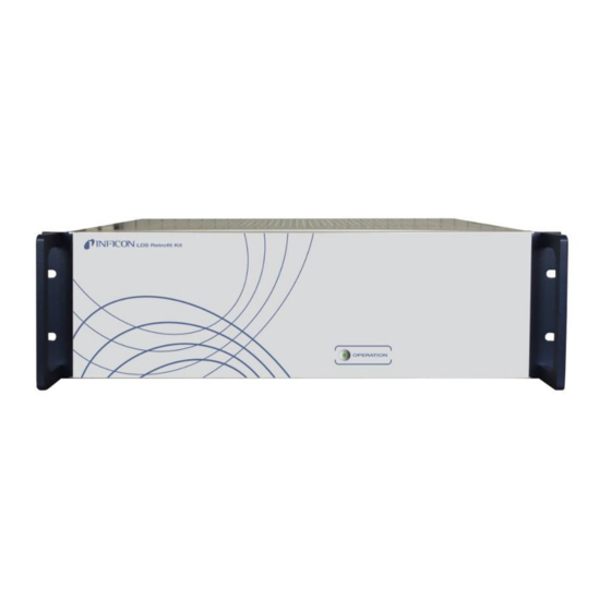
- Page 1 Translation of the original operating instructions LDS Retrofit Kit Electronic module Catalog No. 560-400 From software version jinb10en1-03-(1903) 2.72 (LDS3000) / 2.72 (CU1000)
- Page 2 INFICON GmbH Bonner Strasse 498 50968 Cologne, Germany...
-
Page 3: Table Of Contents
INFICON Table of Contents Table of Contents 1 About these instructions ........................... 5 1.1 Warnings.............................. 5 1.2 Other associated documents ........................ 5 1.3 Target groups ............................ 6 2 Safety ................................ 7 2.1 Intended use ............................. 7 2.2 Owner requirements .......................... 7 2.3 Duties of the operator .......................... 8 2.4 Dangers .............................. 8... - Page 4 Table of Contents INFICON 5.8.6.3 LDS3000 vacuum configuration for the operating mode GROSS with pump module.. 24 5.8.6.4 LDS3000 vacuum configuration for the operating mode FINE with pump module .... 25 5.8.6.5 LDS3000 vacuum configuration for the operating mode ULTRA with pump module.. 26 5.8.6.6...
-
Page 5: About These Instructions
INFICON About these instructions | 1 1 About these instructions This document applies to the software version stated on the title page. Product names may occur in the document, which are added for identification purposes only and belong to the respective owner of the rights. -
Page 6: Target Groups
1 | About these instructions INFICON 1.3 Target groups These operating instructions are intended for the owner and for technically qualified personnel with experience in leak detection technology and integration of leak detection devices in leak detection systems. In addition, the installation and use of the device require knowledge of electronic interfaces. -
Page 7: Safety
2.1 Intended use Under certain circumstances the device functions also in the leak detection systems with LDS2000. When installed with a LDS2000 contact the INFICON Service. The device forms the interface between the existing leak detection system and the retrofitted LDS3000. The LDS3000 can then be used without any electrical adaptations. -
Page 8: Duties Of The Operator
2 | Safety INFICON • Keep this instruction manual available on site. Personnel qualifications • Only instructed personnel should be permitted to work with and on the device. The instructed personnel must have received training on the device. • Make sure that authorized personnel have read and understood the operating instructions and all other applicable documents. -
Page 9: Shipment, Transport, Storage
Shipment, Transport, Storage | 3 3 Shipment, Transport, Storage Shipment Item Quantity LDS retrofit kit Operating instructions Power supply line 24 V, 3 m Power supply line 24V, 5 m EU power supply cord 2.5 m USA power supply cord 2.5 m Table 1: Shipment... -
Page 10: Description
LDS1000/LDS2010. The device is installed in connection with a LDS3000. Under certain circumstances the device functions also in the leak detection systems with LDS2000. When installed with a LDS2000 contact the INFICON Service. The device forms the interface between the existing controller of the leak detection system and the retrofitted LDS3000. -
Page 11: Technical Data
INFICON Description | 4 Fig. 2: Rear view 1 Fuse T 0.8 A 7 Digital out, relay output 2 Connection for module IO1000 8 Connection for control unit CU1000 3 Connection multifunction PLC 9 24 V DC Out 4 RS 232 port, sub-D, 9-pin 10 Power cord connector with 2 pcs. - Page 12 4 | Description INFICON Max. relative humidity 80% up to 31 °C decreasing linearly from 80% to 50% in the range from 31 °C to 40 °C 50% above 40 °C Max. altitude above sea level 2000 m Table 3: Ambient conditions Power supply 100 V ...
-
Page 13: Installation
INFICON Installation | 5 5 Installation 5.1 Setup WARNING Danger from moisture and electricity Moisture entering the device can lead to personal injury due to electric shocks as well as damage to property due to short circuiting. ► Only operate the device in a dry environment. -
Page 14: Connect The Device With The Msb Box Of The Lds3000
5 | Installation INFICON 5.2 Connect the device with the MSB box of the LDS3000 The connections vary depending on the version of the CU1000. Select one of the two installation versions for the CU1000 and connect the device according to the selected installation version: •... -
Page 15: Connecting The Device With External Installation Of Cu1000
INFICON Installation | 5 5.3 Connecting the device with external installation of CU1000 Fig. 3: Connection scheme, CU1000 installed externally 1 LDS retrofit kit 5 Control unit CU1000 2 Power supply line 24 V 6 Connection cable IO1000 3 Connection cable CU1000... -
Page 16: Connect The Device When Installing The Cu1000 In The Installation Slot Of The Device
► Separate the device from the power supply and secure against being switched on again. Fig. 4: Connection scheme, CU1000 installed in the installation slot of the device 1 LDS retrofit kit 4 Power supply line 24 V 2 Customer specific connections... -
Page 17: Install And Connect The Cu1000
INFICON Installation | 5 5.4.1 Install and connect the CU1000 DANGER Life threatening hazard from electric shock ► Switch off the device and disconnect from the mains. To remove the cover of the CU1000 installation slot, loosen the 4 securing screws. -
Page 18: Connect The Device To The Mains Power
Before conversion, note the user defined settings of the existing LDS1000/ LDS2010 for later use. Switch on the LDS retrofit kit. On the touchscreen select the CU1000 "Menu (icon) > Settings > Setup > Compatibility". Select the setting for the existing system: "LDS1000" or "LDS2010" and confirm with "OK". -
Page 19: Make The Vacuum Connection Between The Device And The Existing Leak Detection System
INFICON Installation | 5 5.8 Make the vacuum connection between the device and the existing leak detection system. The vacuum technical specifications of the LDS3000 are different to that of the LDS1000. Adapt for the exchange of the vacuum technical configuration. -
Page 20: Recommended System Configuration For The Operating Mode Gross With Pump Module
5 | Installation INFICON 5.8.3 Recommended system configuration for the operating mode GROSS with pump module Fig. 6: LDS1000 vacuum configuration for the operating mode GROSS with pump module 1 Mass spectrometer module 11 DUT 2 Pump module (option) 12 Test chamber... -
Page 21: Recommended System Configuration For The Operating Mode Fine With Pump Module
INFICON Installation | 5 with this inlet pressure. The pump valve con only be closed when the pumping speed of the pump module is so large that the vacuum pressure in the test chamber does not rise (> 3 mbar). -
Page 22: Lds3000 Operating Modes
5 | Installation INFICON 5.8.5 LDS3000 operating modes The LDS3000 has three possible operating modes for vacuum applications: • GROSS • FINE • ULTRA The LDS3000 operates with two selectable turbo pump rotational speeds: • 1000 Hz • 1500 Hz... -
Page 23: Lds3000 Configuration
INFICON Installation | 5 5.8.6 LDS3000 configuration 5.8.6.1 Connection LDS3000 Fig. 8: Connection LDS3000 1 ULTRA (DN1 6 KF) 4 GROSS (DN 16 KF) 2 FINE (DN 16 KF) 5 FINE (DN 16 KF) 3 GROSS (DN 16 KF) 6 ULTRA (DN 25 KF) 5.8.6.2 LDS3000 specification... -
Page 24: Lds3000 Vacuum Configuration For The Operating Mode Gross With Pump Module
5 | Installation INFICON • Pumping speed: ≥ 2.5 m • Final pressure (total): ≤ 6·10 mbar 5.8.6.3 LDS3000 vacuum configuration for the operating mode GROSS with pump module Fig. 9: LDS3000 vacuum configuration for the operating mode GROSS with pump module... -
Page 25: Lds3000 Vacuum Configuration For The Operating Mode Fine With Pump Module
INFICON Installation | 5 5.8.6.4 LDS3000 vacuum configuration for the operating mode FINE with pump module Fig. 10: LDS3000 vacuum configuration for the operating mode FINE with pump module 1 Internal calibration leak (option) 8 Test chamber 2 Mass spectrometer 9 Tracer gas supply... -
Page 26: Lds3000 Vacuum Configuration For The Operating Mode Ultra With Pump Module
5 | Installation INFICON 5.8.6.5 LDS3000 vacuum configuration for the operating mode ULTRA with pump module Fig. 11: LDS3000 vacuum configuration for the operating mode ULTRA with pump module 1 Internal calibration leak (option) 8 Test chamber 2 Mass spectrometer 9 Tracer gas supply... -
Page 27: Comparison Of The Specifications Lds1000 And Lds3000
INFICON Installation | 5 5.8.6.6 Comparison of the specifications LDS1000 and LDS3000 Note: Please note that the LDS1000 switches to the standby state after booting without external wiring. The LDS3000, on the other hand, switches directly to measuring mode. In the following graph the specification of both devices, the LDS1000 and the LDS3000 are in two separate diagrams each with the same scaling, this is to make comparison easier. -
Page 28: Vacuum Connection Transfer For The Operating Mode Gross
5 | Installation INFICON practical detection limit is only in the range 1 x 10 mbar l/s. With working pressures between 1 mbar and 3 mbar only the GROSS connection of the LDS3000 with the reduced response time and the lower sensitivity (up to 1 x 10 mbar l/s) can be used. -
Page 29: Vacuum Transfer For The Operating Mode Fine
INFICON Installation | 5 5.8.7.2 Vacuum transfer for the operating mode FINE The maximum transfer pressure with the LDS1000 is 3 mbar. The transfer pressure for the LDS3000 with the FINE connection at 1000 Hz is reduced to 0.9 mbar. The transfer pressure must therefore by less than 1 mbar to ensure a safe operation with "FINE". -
Page 30: Operation
6 | Operation INFICON 6 Operation WARNING Danger from moisture and electricity Moisture entering the device can lead to personal injury due to electric shocks as well as damage to property due to short circuiting. ► Only operate the device in a dry environment. -
Page 31: Error Messages
INFICON Error messages | 7 7 Error messages If there are any faults to the power supply or if the MSB box is not connected the operating display goes out, see Device setup [} 10]. If there is a CU1000 control unit, the fault messages are shown on the display of the CU1000. -
Page 32: Maintenance And Repair
8 | Maintenance and repair INFICON 8 Maintenance and repair The device is maintenance free. 8.1 Cleaning the device Switch off the device and disconnect from the mains. When cleaning the housing, use an agent accepted for synthetic and metal surfaces (for example a light household cleaner). -
Page 33: Decommissioning The Device
INFICON Decommissioning the device | 9 9 Decommissioning the device 9.1 Disposing of the device The device can either be disposed of by the operator or be sent to the manufacturer. The device consists of materials that can be recycled. This option should be exercised to prevent waste and also to protect the environment. -
Page 34: Appendix
10 | Appendix INFICON 10 Appendix 10.1 CE Declaration of Conformity 34 / 36 LDS-Retrofit-Kit-Operating-Instructions-jinb10en1-03-(1903)
Need help?
Do you have a question about the LDS Retrofit Kit and is the answer not in the manual?
Questions and answers