Advertisement
Available languages
Available languages
Quick Links
Installation and Commissioning
quick start
125A - 630A
EN
ATyS
STEP 1
Cabinet / Back Plate
Installation
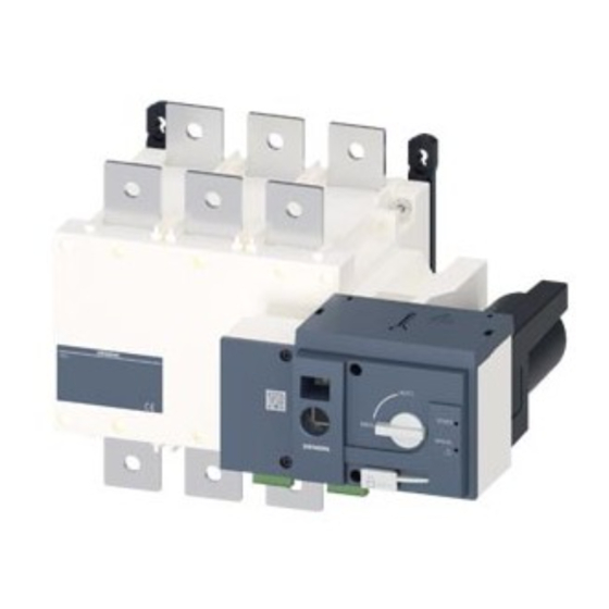
Motorised Source Changeover Switch
Preliminary operations
Check the following upon delivery and after removal of the
packaging:
Packaging and contents are in good condition.
n
The product reference corresponds to the order.
n
Contents should include:
n
Qty 1 x ATyS
Qty 1 x Emergency handle and fixing clip
Quick Start instruction sheet
Warning
Risk of electrocution, burns or injury to persons and /
or damage to equipment.
This Quick Start is intended for personnel trained in the
installation and commissioning of this product. For further
details refer to the product instruction manual available on
the SOCOMEC website.
n
This product must always be installed and commissioned
by qualified and approved personnel.
Maintenance and servicing operations should be
n
performed by trained and authorised personnel.
Do not handle any control or power cables connected to
n
the product when voltage may be, or may become present
on the product, directly through the mains or indirectly
through external circuits.
Always use an appropriate voltage detection device to
n
confirm the absence of voltage.
Ensure that no metal objects are allowed to fall in the
n
cabinet (risk of electrical arcing).
Failure to observe good enginering practises as well as to
follow these safety instructions may expose the user and
others to serious injury or death.
Risk of damaging the device
In case the product is dropped or damaged in any way it
n
is recommended to replace the complete product.
Accessories
Bridging bars and connection kits.
n
STEP 6B
Control voltage transformer (400Vac -> 230Vac).
n
DC power supply (12/24Vdc -> 230Vac).
n
Mounting spacers to raise the product x 10mm.
n
Phase barriers.
n
Terminal shrouds.
n
Terminal screens.
n
Auxiliary contacts (Additional).
n
n
Padlocking in 3 positions (I - O - II).
Lockout accessories (RONIS - EL II AP).
I
n
n
Door escutcheon frame.
Control relay ATyS C30 + D10 or D20.
n
n
Control relay ATyS C40.
For further details, please refer to the instruction manual in
chapter - "Spare parts and accessories"
www.socomec.com
To download: brochures, catalogues and technical manuals.
STEP 6C
Printing informations: 1 color Black. White paper 90g/m
2
.
Printing size: 420x297. Final size 210x297. This page visible first.
Non contractual document.
541 629 B - 09/13 - EN
Subject to change without notice.
STEP 2
STEP 3
STEP 4
STEP 5
Connecting the
COMMAND /
Power SUPPLY
ChECk
POWER section
CONTROL terminal
terminal connections
connections
Clip for
storage of
the
emergency
handle
STEP 5
Manual Operation
Check
0
Whilst in manual mode, check the
wiring and if ok power up the
product.
AUT
LED "Power" Green: ON
LED Manuel/Defaut Red
(Product not Available): ON
II
STEP 6A
Automatic Operation
Ensure that the emergency handle is
not inserted in the product and turn
the mode selector to the AUT position.
LED "Power" Green: ON
LED Manuel/Default: OFF
___________________________________________________________
AUT
Impulse logic
order I
order 0
Padlocking Mode
order II
(as standard : in position O)
position I
position 0
position II
Imp. ≥60ms
AUT
To enable control, close contact 312 with 317.
To force the product to 0 position/OFF bridge
the contact 313 with 317.
For contactor logic bridge contact 316 with 317.
To operate: close the contact corresponding to
the desired position.
STEP 1
STEP 6A
Installation
Control by an external
order (AUTO)
Attention:
Recommended
Ok
Ensure that
the product is
installed on a
STEP 6B
flat rigid
Emergency Manual
surface.
Operation
Orientation:
STEP 6C
Door cut-out for front panel.
Padlocking
138
20
Ø7
Ø9
STEP 4
STEP 3
STEP 3
CONTROL / COMMAND Terminals - Ensure that the product is in Manual Mode.
Contactor logic
STEP 4
Power Supply Terminal - Remove the Top cover to access and connect the terminal - Replace the cover before putting in service.
1
maintened
Dimensions in mm.
M
J1
M
J1
T
U
C
T
U
W
T
U
Ø7
125 A
160 A
200 A
3 P
4 P
3 P
4 P
3 P
4 P
U
J 1
34
34
34
34
34
34
Ø9
M
120
150
120
150
120
150
T
36
36
36
36
36
36
W
C
244
244
244
244
244
244
U
20
20
20
20
20
20
W
W
9
9
9
9
9
9
U
CA
10
10
10
10
10
10
Ø7
W
U
Ø9
STEP 2
Power Terminal Connections
U
W
To be connected using terminal lugs, rigid or flexable busbars.
FRAME B3
125 A
160 A
200 A
W
Minimum cable sec-
50
70
95
U
tion Cu (mm
2
) at Ith
Minimum cable sec-
-
-
-
tion Cu (mm
2
) at Ith
Maximum cable
50
95
150
U
section Cu (mm
2
)
Maximum Cu busbar
20
20
32
width (mm)
Type of screw
M8
M8
M8
Recommended tight-
8.3
8.3
8.3
ening torque (N.m)
Maximum tightening
13
13
13
torque (N.m)
1
1
2
312 313 314 315 316 317
CONTROL
Connect the product with a cable of section of 1,5 to 2,5 mm
Screw M3 - Tightening torque: min.: 0.5 Nm - max.: 0.6 Nm
3
2
C
21
21
C
21
250 A
315 A
400 A
500 A
630 A
3 P
4 P
3 P
4 P
3 P
4 P
3 P
4 P
3 P
4 P
35
35
35
35
35
35
34
34
34
34
160
210
160
210
160
210
210
270
210
270
50
50
50
50
50
50
65
65
65
65
244
244
244
244
244
244
320
320
320
320
25
25
25
25
35
35
32
32
45
45
11
11
11
11
11
11
13
13
13
13
15
15
15
15
15
15
20
20
20
20
FRAME B4
FRAME B5
250 A
315 A
400 A
500 A
630 A
120
185
240
2x150
2x185
-
-
-
2x30x5
2x40x5
150
240
240
2x300
2x300
32
32
32
50
50
M10
M10
M10
M12
M12
20
20
20
40
40
26
26
26
45
45
2
63A 64A 24 14 04 13
OUTPUTS
2
.
Advertisement

Subscribe to Our Youtube Channel
Related Manuals for socomec ATyS 12SA


Summary of Contents for socomec ATyS 12SA
- Page 1 For further Power Terminal Connections details refer to the product instruction manual available on the SOCOMEC website. To be connected using terminal lugs, rigid or flexable busbars. This product must always be installed and commissioned...
- Page 2 ÉTAPE 4 Bornier ALIMENTATION - Retirer le cache pour accéder à l'alimentation du produit et connecter le bornier. Repositionner le cache avant de mettre en service. ordre I www.socomec.com ordre 0 Espace téléchargement : brochures, catalogues et notices. Mode cadenassage ÉTAPE 6C...
Need help?
Do you have a question about the ATyS 12SA and is the answer not in the manual?
Questions and answers