Table of Contents
Advertisement
Quick Links
Installation, Operation and Maintenance Manual
D–EIMAC01207-15EN
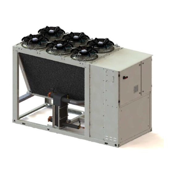
Air Cooled Chiller Multiscroll
EWAQ~G-
SS (Standard Efficiency - Standard Noise)
SR (Standard Efficiency - Reduced Noise)
XS (High Efficiency - Standard Noise)
XR (High Efficiency - Reduced Noise)
Refrigerant: R410A
Original Instructions
D-EIMAC01207-15EN - 1/22
Advertisement
Table of Contents

Related Manuals for Daikin EWAQ~G-SS


Summary of Contents for Daikin EWAQ~G-SS
- Page 1 Installation, Operation and Maintenance Manual D–EIMAC01207-15EN Air Cooled Chiller Multiscroll EWAQ~G- SS (Standard Efficiency - Standard Noise) SR (Standard Efficiency - Reduced Noise) XS (High Efficiency - Standard Noise) XR (High Efficiency - Reduced Noise) Refrigerant: R410A Original Instructions D-EIMAC01207-15EN - 1/22...
-
Page 2: Table Of Contents
Table of contents Description ................................. 3 General Information ..............................3 Receiving the unit ............................... 3 Storage ..................................3 Operation ..................................3 Figure 1 - Description of the labels applied to the electrics panel ................4 Figure 2 - Operating limits............................4 Safety .................................. -
Page 3: Description
Thank you for purchasing this chiller This manual is an important support document for qualified personnel but it is not intended to replace such personnel. Receiving the unit READ THIS MANUAL CAREFULLY BEFORE INSTALLING AND STARTING UP THE UNIT. The unit must be inspected for any possible damage IMPROPER INSTALLATION COULD RESULT IN ELECTRIC SHOCK, immediately upon reaching final place of installation. -
Page 4: Figure 1 - Description Of The Labels Applied To The Electrics Panel
Figure 1 - Description of the labels applied to the electrics panel Identification of labels 1 – Slack electrical cable warning 5 – Type of gas 2 – Hazardous voltage warning 6 – Non flammable gas symbol 3 – Electrical hazard symbol 7 –... - Page 5 EWAQ G SR (Standard efficiency – Reduced noise) Water temperature at outlet (°C) EWAQ G XS (High efficiency – Standard noise) Water temperature at outlet (°C) D-EIMAC01207-15EN - 5/22...
- Page 6 EWAQ G XR (High efficiency - Reduced noise) Water temperature at outlet (°C) Notes The diagram shows the guide lines for the range of operating limits. Refer to the Chiller Selection Software (CSS) for the true operating limits under working conditions for each model. Legend Ambient temperature (°C) = Air temperature at condenser inlet (°C) Water temperature at outlet (°C) = Water temperature at evaporator outlet (°C)
-
Page 7: Safety
Table 3 - Air heat exchanger - Correction factor at altitude Legend A = Altitude above sea level (m) B = Atmospheric pressure (mbar) C = Refrigeration capacity correction factor D = Power consumption correction factor - The maximum operating altitude is 2000 metres above sea level - If the unit is to be installed at an altitude of between 1000 and 2000 metres above sea level, contact manufacturer. -
Page 8: Positioning And Assembly
Positioning and assembly The unit must be installed on a solid, perfectly level base. For earthing purposes, a solid cement base, that is wider than the unit, must be made. This base must be able to support the weight of the unit. Anti-vibration supports must be installed between the frame of the unit and the cement base of the steel beams;... -
Page 9: Sound Protection
the weight of the units varies depending on the accessories requested. Figure 4 – Lifting the unit (The illustration only shows the version with 6 fans. The lifting method used for other versions with a different number of fans is identical) N.B.: Follow the lifting instructions provided in the ID plate fastened to the electrical panel 8: 8 –... -
Page 10: Pipe Insulation
The water system must have: It has a clean contact that is electrically connected to Anti-vibrating pipes which reduce the terminals shown in the wiring diagram, and must be transmission of vibrations to the structures. calibrated so that it intervenes when the flow of the Isolating valves to isolate the unit from the water water of the evaporator drops below 80% of the nominal system... -
Page 11: Water Treatment
Circulati Water Possible 2 3 4 ng water supply problems Items to be checked Corrosion pH at 25°C 6.8~8.0 6.8~8.0 + limescale Electrical Corrosion conductivity <40 <30 + limescale [mS/m] at 25°C Chloride ions <50 <50 Corrosion [mg Cl˜/l] Sulphate ions <50 <50 Corrosion... -
Page 12: Anti-Freeze Protection For Evaporators And Recovery Exchangers
Anti-freeze protection for evaporators and recovery Minimum water Maximum G EWAQ~G SR exchangers flow water flow model When the entire system of the cooling installation is EWAQ075G-SR 1.98 3.96 being designed, two or more of the following anti-freeze EWAQ085G-SR 2.28 4.56 protection methods should be considered at the same EWAQ100G-SR... -
Page 13: Wiring At The Installation Site
The unit must be started for the first time by must be supported by adequate systems. DAIKIN authorised personnel ONLY. The unit must absolutely not be started, even for a very short period of time, without having checked it in minute detail filling out the following list at the same time. -
Page 14: Open The Isolation And/Or Shut Off Valves
Open the isolation and/or shut off valves Checks to be performed before starting Before start-up, make sure that all the isolation and/or the unit switch off valves are completely open. Check for exterior damage User responsibilities Open all the closing valves It is essential that the user is properly trained and Make sure that all the parts of the unit are becomes familiar with the system before operating the... -
Page 15: Mandatory Periodical Checks And Start-Up Of Groups (Units)
7. Unless specifically agreed at the time of order, the For Groups belonging to this category, various national flow of water of the evaporator must never exceed laws call for a periodical control by an authorised 120% or be below 80% of the nominal capacity and in organisation. -
Page 16: Important Information Regarding The Refrigerant Used
Important information regarding the refrigerant used Product lifespan This product contains fluorinated greenhouse gases. Our products have a lifespan of 10 (ten) years. Do not release the refrigerant gas into the atmosphere. Disposal Refrigerant type: R410A The unit is made of metal, plastic and electronic components. -
Page 17: Figure 5 – Unit Wiring In Installation Site
Figure 5 – Unit wiring in installation site Legend Analogue Inputs A.R. Remote ON / OFF M/S TS Main/Secondary Temperature Sensor M/S BC Main/Secondary Connection Box D.L. Request Limit Digital Inputs Digital Outputs Double Setting Point External failure Evaporator flow switch General Alarm KPE-1 Pump 1 water evaporator... - Page 18 Typical refrigerant circuit – The number of compressors and water inlet and outlet are indicative. Please refer to the machine dimensional diagrams for exact water connections. D-EIMAC01207-15EN - 18/22...
- Page 19 Typical refrigerant circuit with partial heat recovery – The number of compressors and water inlet and outlet are indicative. Please refer to the machine dimensional diagrams for exact water connections. D-EIMAC01207-15EN - 19/22...
- Page 20 Typical refrigerant circuit with total heat recovery – The number of compressors and water inlet and outlet are indicative. Please refer to the machine dimensional diagrams for exact water connections. D-EIMAC01207-15EN - 20/22...
- Page 21 Legend Compressor Heat recovery Condenser coil and Axial ventilator Filter Solenoid valve Thermostatic valve ¼ SAE Flare Valve Heat exchanger Sight glass Electronic expansion valve Service port Evaporator Evaporator water inlet connection Evaporator water outlet connection Heat recovery water inlet connection Heat recovery water outlet connection...
- Page 22 The present publication is drawn up by for information only and does not constitute an offer binding upon Daikin Applied Europe S.p.A.. Daikin Applied Europe S.p.A. has compiled the content of this publication to the best of its knowledge. No express or implied warranty is given for the completeness, accuracy, reliability or fitness for particular purpose of its content, and the products and services presented therein.
Need help?
Do you have a question about the EWAQ~G-SS and is the answer not in the manual?
Questions and answers