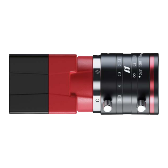
Table of Contents
Advertisement
Quick Links
Q
R
UICK
EFERENCE
Pin Assignment for Alvium Cameras
Alvium G1
Alvium 1500 C
Alvium 1800 C
Scope
This document gives an overview for camera connections with I/O cables for GigE and USB cameras and
with FPC cables for CSI-2 cameras. To avoid damage to your cameras and connected peripherals, see the
corresponding Alvium user guide for instructions and further information.
Helpful downloads
Download
User guides for Alvium cameras
Additional documentation
Accessories, such as I/O cables
Link
www.alliedvision.com/en/support
www.alliedvision.com/en/products/accessories
Table 1: Helpful downloadss
Page 1 of 5
V1.0.0
2023-Feb-13
Alvium 1800 U
Alvium G5
Advertisement
Table of Contents

Summary of Contents for Allied Vision Alvium G1
- Page 1 UICK EFERENCE Pin Assignment for Alvium Cameras V1.0.0 2023-Feb-13 Alvium G1 Alvium 1800 U Alvium 1500 C Alvium G5 Alvium 1800 C Scope This document gives an overview for camera connections with I/O cables for GigE and USB cameras and with FPC cables for CSI-2 cameras.
- Page 2 Black C-GND Transparent C-GND *Color coding applies only to Allied Vision I/O cables with screw locks. Table 2: 7-pin JST BM07B-SRSS-TBT I/O connector pin assignment Compatible I/O cables I/O cables for Alvium USB cameras • 12319: 7-pin JST I/O cable without screw locks 0.4 m Observe for connecting: All lines are blue.
- Page 3 Damage to camera electronics The color coding shown in Table 3 applies to Allied Vision I/O cables for Alvium G1 and Alvium G5 cameras. When using third party cables, the camera can be damaged if you do not observe different color codings.
- Page 4 Pin Assignment for Alvium Cameras Alvium CSI-2 cameras Signal Direction VCC-EXT-IN PWR IN EXT-GPIO0-I2C_SCL IN/OUT VCC-EXT-IN EXT-GPIO0-I2C_SCL I2C control EXT-GPIO1-I2C_SDA IN/OUT EXT-GPIO1-I2C_SDA VCC-EXT-IN PWR IN VCC-EXT-IN EXT-GPIO2 User control EXT-GPIO3 EXT-GPIO2 IN/OUT VCC-EXT-IN EXT-GPIO3 IN/OUT CSI2-TXD3_N CSI2-TXD3_P VCC-EXT-IN PWR IN CSI2-TXD3_N CSI2-TXD2_N CSI2-TXD2_P...
- Page 5 All content is subject to change without notice. All trademarks, logos, and brands cited in this document are property and/or copyright material of their respective owners. Use of these trademarks, logos, and brands does not imply endorsement. Copyright © 2023 Allied Vision Technologies GmbH. All rights reserved. Page 5 of 5...


Need help?
Do you have a question about the Alvium G1 and is the answer not in the manual?
Questions and answers