Allied Vision 1800 U-050m User Manual
Usb3 vision cameras
Hide thumbs
Also See for 1800 U-050m:
- User manual (104 pages) ,
- User manual (206 pages) ,
- Quick reference (5 pages)

Related Manuals for Allied Vision 1800 U-050m


Summary of Contents for Allied Vision 1800 U-050m
- Page 1 USB3 V ISION AMERAS Alvium USB Cameras User Guide V3.1.3 Allied Vision Technologies GmbH // Taschenweg 2a, 07646 Stadtroda / Germany 2020-Mar-12...
-
Page 2: Alvium Usb Cameras At A Glance
Alvium USB cameras at a glance Alvium USB cameras at a glance Read this document carefully Learn to avoid damage to your Alvium USB camera and use it in the most safe and efficient way. Bandwidth and maximum frame rate The default bandwidth for Alvium USB is 200 MBps. -
Page 3: What Else Do You Need
Alvium USB cameras at a glance What else do you need? This is a selection of helpful downloads: Document Link Alvium USB Cameras Quickstart Guide (multilingual) www.alliedvision.com/en/support/ technical-documentation/alvium-usb- Alvium Cameras Features Reference documentation Alvium Cameras Hardware Options Alvium Cameras Accessory Guide www.alliedvision.com/en/support/ Optimum Heat Dissipation for Housed Alvium Cameras technical-documentation/alvium-usb-... -
Page 4: Contact Us
T// +1 978 225 2030 California: +1 408 721 1965 Asia-Pacific T// +65 6634 9027 China T// +86 21 64861133 Headquarters Allied Vision Technologies GmbH Taschenweg 2a 07646 Stadtroda, Germany T// +49 36428 677-0 F// +49 36428 677-28 Alvium USB Cameras User Guide V3.1.3... -
Page 5: Table Of Contents
Contents Contents Alvium USB cameras at a glance ..........2 Shipping contents . - Page 6 Alvium 1800 U-050m/c ........
- Page 7 Contents Open Housing S-Mount ..............80 Open Housing CS-Mount .
- Page 8 Contents Non-isolated, programmable GPIOs ............117 GPIOs description .
-
Page 9: Document History And Conventions
Document history and conventions This chapter includes: Document history ..............10 Conventions used in this user guide........11 Naming and terms ..............12 Alvium USB Cameras User Guide V3.1.3... -
Page 10: Document History
V3.0.0 2020-Jan-06 • Added Alvium 1800 U-040m/c, U -158m/c, and U-501m NIR models. V2.0.0 2019-Oct-18 • Added Alvium 1800 U-050m/c and U -120m/c models. • Updated contents about bandwidth. • Updated screenshots for camera driver installation. • Added Dark current compensation on page 132. -
Page 11: Conventions Used In This User Guide
Document history and conventions Conventions used in this user guide To give this document an easily understood layout and to emphasize important information, the following typographical styles and symbols are used: Typographic styles Style Function Emphasis Programs, or highlighting important things Names for GenICam features Feature names Options for GenICam features... -
Page 12: Naming And Terms
Document history and conventions Naming and terms Camera model naming Alvium cameras are named to identify model properties. For example, Alvium 1800 U-500c is composed of: Alvium 1800 Content Camera Camera series details Interface Resolution Color/ series monochrome Examples Alvium 1500: Basic feature set C: MIPI CSI-2 500: 5.0 MP... - Page 13 Document history and conventions Term or acronym Description Reference GPIOs General purpose inputs and outputs GPIOs description on page 117 (non-isolated) Global reset shutter Shutter types and effects on page 135 H × V Horizontal × Vertical (sensor resolution) Alvium 1800 U-500m/c on page 53 Kilobyte Alvium 1800 U-500m/c...
-
Page 14: Compliance, Safety, And Intended Use
Compliance, safety, and intended use This chapter includes: Compliance notifications ............15 Intended use ................. 18 Copyright and trademarks ............ 18 Your safety................19 Product safety ............... 21 Alvium USB Cameras User Guide V3.1.3... -
Page 15: Compliance Notifications
Compliance, safety, and intended use Compliance notifications WEEE-Registration number: DE 59201569 For customers in the USA Closed housing cameras only: FCC Class B digital device This equipment has been tested and found to comply with the limits for a Class B digital device, pursuant to part 15 of the FCC Rules. -
Page 16: United States Of America: Supplier Declaration Of Conformity
1. This device may not cause harmful interference, and 2. this device must accept any interference received, including interference that may cause undesired operation. Party issuing Supplier's Declaration of Conformity Allied Vision Technologies GmbH Taschenweg 2a 07646 Stadtroda Germany T// +49 (36428) 677-106 quality@alliedvision.com... -
Page 17: Bare Board And Open Housing Cameras
Interface cables, power cables, and I/O cables are sensitive to electromagnetic interference. • Use shielded cables only. • We recommend using cables offered by Allied Vision. • Avoid coiling. • We recommend using GPIOs only in environments with low electromagnetic interference. -
Page 18: Intended Use
We are offering standard products as well as customized solutions. Intended use of Allied Vision product is the integration into Vision systems by professionals. All Allied Vision product is sold in a B2B setting. -
Page 19: Your Safety
Compliance, safety, and intended use Your safety This section informs about issues related to your personal safety. Descriptions explain how to avoid hazards and operate Alvium USB cameras safely. Handling lens mounts The lens mount thread has sharp edges. Be careful these edges do not cut your skin when mounting or unmounting lenses. -
Page 20: Camera Mounting
Compliance, safety, and intended use For your safety and to improve camera performance, operate the camera: • Mounted to a base with a high thermal conductivity • With lens or other optical components mounted • With a heat sink mounted that has large surface areas (closed housing cameras include a heat sink) •... -
Page 21: Product Safety
Compliance, safety, and intended use Product safety To prevent material damage, read the following and understand how to safely handle and operate the camera. Get helpful details about electrical connections and learn how to optimize camera performance. Electrical connections ESD is dangerous for electronic devices, especially when tools or hands get in contact with connectors and electronic components. - Page 22 Compliance, safety, and intended use GPIOs To avoid damage to the camera, keep maximum input voltage below 5.5 VDC and maximum current below 12 mA per output. See Specifications on page 27 for details. The maximum length for I/O cables must not exceed 30 meters. Reverse polarity If Alvium USB cameras are externally powered with reverse polarity, the cameras can be damaged.
-
Page 23: Handling Bare Board Cameras
Proper cable handling enables reliable performance: • Use only shielded cables to avoid electromagnetic interferences. • Please use cables recommended by Allied Vision. • Avoid unnecessary bending to prevent damage to the cables. • Avoid coiling to prevent electromagnetic interference. -
Page 24: Optical Components
Compliance, safety, and intended use Optical components Provide the following conditions to keep dirt and droplets out of the optical system of camera and lens: • Dust-free environment • Low relative humidity • No condensation. When camera or lens are stored: •... - Page 25 Compliance, safety, and intended use Lenses Maximum protrusion The sensor, filter, lens, or camera electronics can be damaged if a lens exceeding maximum protrusion is mounted to the camera. Use lenses with a maximum protrusion within camera specifications. Figure 2 shows maximum protrusion.
-
Page 26: Heat Sinks And Conductive Media
Compliance, safety, and intended use Heat sinks and conductive media The camera can be damaged by overheating if heat sink or conductive media are not used properly. Heat sinks Adhere to the instructions and safety notes provided by the manufacturer of the heat sink. -
Page 27: Specifications
This chapter includes: Applied standards ..............28 Notes on specifications............29 Alvium 1800 U-040m/c ............33 Alvium 1800 U-050m/c ............37 Alvium 1800 U-120m/c ............41 Alvium 1800 U-158m/c ............45 Alvium 1800 U-319m/c ............49 Alvium 1800 U-500m/c ............53 Alvium 1800 U-501m NIR ............. -
Page 28: Applied Standards
This enables to operate cameras with USB3 Vision, GigE Vision, or CoaXPress interfaces and Alvium USB cameras with a common software. GenICam consists of multiple modules for different tasks. Allied Vision cameras and software use these modules, like the SFNC that standardizes feature names and types via an XML file or the transport layer interface (GenTL) used to grab images. -
Page 29: Shock And Vibration
Specifications Shock and vibration Closed and open housing cameras were tested successfully according to the following standards: • IEC 60068-2-6, sinusoidal vibration testing • IEC 60068-2-27, shock testing • IEC 60068-2-64, random vibration testing. If you need more details, please contact support@alliedvision.com. Notes on specifications This section defines the conditions for specifications stated in this chapter.. -
Page 30: Exposure Time And Frame Rate
Specifications Exposure time and frame rate Stated values were measured for a maximum bandwidth of 375 MBps for Typical operation, using the following test setup: Component Property Desktop workstation Dell Precision T5500 Precision (EHW400) Chipset Chipset Intel X5520 Intel Xeon X5670 (6 cores) CPU frequency 2.93 GHz 12 GB... -
Page 31: Sensor Shutter Types And Triggering
Specifications Triggering The following table shows how the shutter mode impacts available frame rates: Sensor type Shutter mode Trigger mode Available frame rates ROI frame rates Global shutter Freerun Maximum values Increased values Global shutter Global shutter External trigger Maximum values Increased values Rolling shutter Freerun... -
Page 32: Power Consumption
Specifications Power consumption Data is given for typical operation: • Factory settings (camera after startup) • Minimum exposure time • Maximum frame rate • Full resolution • Mono8 pixel format (also for color models) • Camera operation in freerun mode •... -
Page 33: Alvium 1800 U-040M/C
Specifications Alvium 1800 U-040m/c Feature Specification 1800 U-040m (monochrome) 1800 U-040c (color) Sensor model Sony IMX287 Resolution 728 (H) × 544 (V); 0.4 megapixels Sensor type CMOS Shutter type Global shutter Sensor size Type 1/2.9; 5 mm × 3.8 mm; 6.3 mm diagonal Pixel size 6.9 µm ×... - Page 34 Specifications Feature Specification 1800 U-040m/c Storage temperature -10 °C to +70 °C ambient temperature Hardware Housing Cooling areas Mainboard option Bare board Not applicable Operating temperature +5 °C to +85 °C +5 °C to +65 °C +5 °C to +85 °C Open housing Closed housing +5 °C to +65 °C...
-
Page 35: Absolute Qe
Specifications Absolute QE Blue QE Green QE Red QE Monochrome QE Sony IMX287 absolute QE 1000 Wavelength [nm] Figure 3: Absolute QE for 1800 U-040m/c (Sony IMX287) Spectral response Figure 4: Spectral response for 1800 U-040m/c (Sony IMX287) Alvium USB Cameras User Guide V3.1.3... -
Page 36: Roi Frame Rates
Specifications ROI frame rates Values were measured for typical operation, using the test setup defined in Exposure time and frame rate on page 30. To reach the maximum frame rate available for typical operation, the bandwidth for image traffic is 200 MBps. Increasing the value DeviceLinkThroughputLimit does not increase frame rates. -
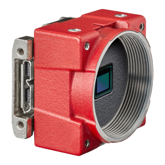
Page 37: Alvium 1800 U-050M/C
Timed, TriggerControlled, TriggerWidth Power requirements Power over USB; External power Power consumption USB power: 1.5 W (typical, at 5 VDC) External power: 1.7 W Table 11: Alvium 1800 U-050m/c specifications (sheet 1 of 2) Alvium USB Cameras User Guide V3.1.3... - Page 38 GenICam V2.0 (GenICam Access) Mounting the heat sink on page 102. Output by DeviceTemperature Temperature values must be observed for the housing and for the cooling areas. Table 11: Alvium 1800 U-050m/c specifications (sheet 2 of 2) Alvium USB Cameras User Guide V3.1.3...
-
Page 39: Absolute Qe
Red QE Monochrome QE ON Semi PYTHON 480 absolute QE 1000 1050 1100 Wavelength [nm] Figure 5: Absolute QE for 1800 U-050m/c (ON Semiconductor PYTHON 480) Spectral response Blue Response Green Response Red Response Monochrome Response 0.300 ON Semi PYTHON 480 spectral response 0.250... -
Page 40: Roi Frame Rates
Maximum × half 245,632 Maximum × minimum 6,464 1,332 Minimum × maximum 4,864 Minimum × minimum 1,880 Constant for values ≤ 16 pixels Table 12: ROI frame rates for 1800 U-050m/c at 200 MBps Alvium USB Cameras User Guide V3.1.3... -
Page 41: Alvium 1800 U-120M/C
Specifications Alvium 1800 U-120m/c Feature Specification 1800 U-120m (monochrome) 1800 U-120c (color) Sensor model ON Semiconductor AR0135CS Resolution 1280 (H) × 960 (V); 1.2 megapixels Sensor type CMOS Shutter type Global shutter Sensor size Type 1/3; 4.8 mm × 3.6 mm; 6.0 mm diagonal Pixel size 3.75 µm ×... - Page 42 Specifications Feature Specification 1800 U-120m/C Storage temperature -10 °C to +70 °C ambient temperature Hardware Housing Cooling areas Mainboard option Bare board Not applicable Operating temperature +5 °C to +85 °C +5 °C to +65 °C +5 °C to +85 °C Open housing Closed housing +5 °C to +65 °C...
-
Page 43: Absolute Qe
Specifications Absolute QE Blue QE Green QE Red QE Monochrome QE ON Semi AR0135CS absolute QE 1000 1050 1100 Wavelength [nm] Figure 7: Absolute QE for 1800 U-120m/c (ON Semiconductor AR0135CS) Spectral response Blue Response Green Response Red Response Monochrome Response 0.350 ON Semi AR0135CS spectral response 0.300... -
Page 44: Roi Frame Rates
Specifications ROI frame rates Values were measured for typical operation, using the test setup defined in Exposure time and frame rate on page 30. To reach the maximum frame rate available for typical operation, the bandwidth for image traffic is 200 MBps. Increasing the value DeviceLinkThroughputLimit does not increase frame rates. -
Page 45: Alvium 1800 U-158M/C
Specifications Alvium 1800 U-158m/c Feature Specification 1800 U-158m (monochrome) 1800 U-158c (color) Sensor model Sony IMX273 Resolution 1456 (H) × 1088 (V); 1.6 megapixels Sensor type CMOS Shutter type Global shutter Sensor size Type 1/2.9; 5 mm × 3.8 mm; 6.3 mm diagonal Pixel size 3.45 µm ×... - Page 46 Specifications Feature Specification 1800 U-158m/C Storage temperature -10 °C to +70 °C ambient temperature Hardware Housing Cooling areas Mainboard option Bare board Not applicable Operating temperature +5 °C to +85 °C +5 °C to +65 °C +5 °C to +85 °C Open housing Closed housing +5 °C to +65 °C...
-
Page 47: Absolute Qe
Specifications Absolute QE Blue QE Green QE Red QE Monochrome QE Sony IMX273 absolute QE 1000 Wavelength [nm] Figure 9: Absolute QE for 1800 U-158m/c (Sony IMX273) Spectral response Figure 10: Spectral response for 1800 U-158m/c (Sony IMX273) Alvium USB Cameras User Guide V3.1.3... -
Page 48: Roi Frame Rates
Specifications ROI frame rates Values were measured for typical operation, using the test setup defined in Exposure time and frame rate on page 30. To reach the maximum frame rate available for typical operation, the bandwidth for image traffic is 300 MBps. Increasing the value DeviceLinkThroughputLimit does not increase frame rates. -
Page 49: Alvium 1800 U-319M/C
Specifications Alvium 1800 U-319m/c Feature Specification 1800 U-319m (monochrome) 1800 U-319c (color) Sensor model Sony IMX265 Resolution 2064 (H) × 1544 (V); 3.2 megapixels Sensor type CMOS Shutter type Global shutter Sensor size Type 1/1.8; 7.1 mm × 5.3 mm; 8.9 mm diagonal Pixel size 3.45 µm ×... - Page 50 Specifications Feature Specification 1800 U-319m/C Storage temperature -10 °C to +70 °C ambient temperature Hardware Housing Cooling areas Mainboard option Bare board Not applicable Operating temperature +5 °C to +85 °C +5 °C to +65 °C +5 °C to +85 °C Open housing Closed housing +5 °C to +65 °C...
-
Page 51: Absolute Qe
Specifications Absolute QE Blue QE Green QE Red QE Monochrome QE Sony IMX265 absolute QE 1000 Wavelength [nm] Figure 11: Absolute QE for 1800 U-319m/c (Sony IMX265) Spectral response Figure 12: Spectral response for 1800 U-319m/c (Sony IMX265) Alvium USB Cameras User Guide V3.1.3... -
Page 52: Roi Frame Rates
Specifications ROI frame rates Values were measured for typical operation, using the test setup defined in Exposure time and frame rate on page 30. To reach the maximum frame rate available for typical operation, the bandwidth for image traffic is 200 MBps. Increasing the value DeviceLinkThroughputLimit does not increase frame rates. -
Page 53: Alvium 1800 U-500M/C
Specifications Alvium 1800 U-500m/c Feature Specification 1800 U-500m (monochrome) 1800 U-500c (color) Sensor model ON Semiconductor AR0521SR Resolution 2592 (H) × 1944 (V); 5.0 megapixels Sensor type CMOS Shutter type Rolling shutter Sensor size Type 1/2.5; 5.7 mm × 4.3 mm; 7.1 mm diagonal Pixel size 2.2 µm ×... - Page 54 Specifications Feature Specification 1800 U-500m/c Storage temperature -10 °C to +70 °C ambient temperature Hardware Housing Cooling areas Mainboard option Not applicable Bare board Operating temperature +5 °C to +85 °C +5 °C to +85 °C +5 °C to +65 °C Open housing Closed housing +5 °C to +65 °C...
-
Page 55: Absolute Qe
Specifications Absolute QE Blue QE Green QE Red QE Monochrome QE 100% ON Semi AR0521 absolute QE 1000 1050 1100 Wavelength [nm] Figure 13: Absolute QE for 1800 U-500m/c (ON Semiconductor AR0521SR) Spectral response Blue Response Green Response Red Response Monochrome Response 0.400 ON Semi AR0521 spectral response... -
Page 56: Roi Frame Rates
Specifications ROI frame rates 200 to 300 MBps Values were measured for typical operation, using the test setup defined in Exposure time and frame rate on page 30. To reach the maximum frame rate available for typical operation, the bandwidth for image traffic is 350 MBps. - Page 57 Specifications 330 to 375 MBps Values were measured for typical operation, using the test setup defined in Exposure time and frame rate on page 30. To reach the maximum frame rate available for typical operation, the bandwidth for image traffic is 350 MBps. Increasing the value DeviceLinkThroughputLimit does not increase frame rates.
-
Page 58: Alvium 1800 U-501M Nir
Specifications Alvium 1800 U-501m NIR Feature Specification 1800 U-501m NIR (monochrome) Sensor model ON Semiconductor AR0522 Resolution 2592 (H) × 1944 (V); 5.0 megapixels Sensor type CMOS Shutter type Rolling shutter Sensor size Type 1/2.5; 5.7 mm × 4.3 mm; 7.1 mm diagonal Pixel size 2.2 µm ×... - Page 59 Specifications Feature Specification 1800 U-501m NIR (monochrome) Storage temperature -10 °C to +70 °C ambient temperature Hardware Housing Cooling areas Mainboard option Not applicable Bare board Operating temperature +5 °C to +85 °C +5 °C to +85 °C +5 °C to +65 °C Open housing Closed housing +5 °C to +65 °C...
-
Page 60: Absolute Qe
Specifications Absolute QE Monochrome QE 100% ON Semi AR0522 absolute QE 1000 1050 1100 Wavelength [nm] Figure 15: Absolute QE for 1800 U-501m NIR (ON Semiconductor AR0522) Spectral response Monochrome Response 0.450 ON Semi AR0522 spectral response 0.400 0.350 0.300 0.250 0.200 0.150... -
Page 61: Roi Frame Rates
Specifications ROI frame rates 200 to 300 MBps Values were measured for typical operation, using the test setup defined in Exposure time and frame rate on page 30. To reach the maximum frame rate available for typical operation, the bandwidth for image traffic is 350 MBps. - Page 62 Specifications 330 to 375 MBps Values were measured for typical operation, using the test setup defined in Exposure time and frame rate on page 30. To reach the maximum frame rate available for typical operation, the bandwidth for image traffic is 350 MBps. Increasing the value DeviceLinkThroughputLimit does not increase frame rates.
-
Page 63: Alvium 1800 U-507M/C
Specifications Alvium 1800 U-507m/c Feature Specification 1800 U-507m (monochrome) 1800 U-507c (color) Sensor model Sony IMX264 Resolution 2464 (H) × 2056 (V); 5.1 megapixels Sensor type CMOS Shutter type Global shutter Sensor size Type 2/3; 8.5 mm × 7.1 mm; 11.1 mm diagonal Pixel size 3.45 µm ×... - Page 64 Specifications Feature Specification 1800 U-507m/C Storage temperature -10 °C to +70 °C ambient temperature Hardware Housing Cooling areas Mainboard option Bare board Not applicable Operating temperature +5 °C to +85 °C +5 °C to +65 °C +5 °C to +85 °C Open housing Closed housing +5 °C to +65 °C...
-
Page 65: Absolute Qe
Specifications Absolute QE Blue QE Green QE Red QE Monochrome QE Sony IMX264 absolute QE 1000 Wavelength [nm] Figure 17: Absolute QE for 1800 U-507m/c (Sony IMX264) Spectral response Blue Response Green Response Red Response Monochrome Response 0.4000 Sony IMX264 spectral response 0.3000 0.2000 0.1000... -
Page 66: Roi Frame Rates
Specifications ROI frame rates Values were measured for typical operation, using the test setup defined in Exposure time and frame rate on page 30. To reach the maximum frame rate available for typical operation, the bandwidth for image traffic is 200 MBps. Increasing the value DeviceLinkThroughputLimit does not increase frame rates. -
Page 67: Alvium 1800 U-1236M/C
Specifications Alvium 1800 U-1236m/c Feature Specification 1800 U-1236m (monochrome) 1800 U-1236c (color) Sensor model Sony IMX304 Resolution 4112 (H) × 3008 (V); 12.4 megapixels Sensor type CMOS Shutter type Global shutter Sensor size Type 1; 14.2 mm × 10.4 mm; 17.6 mm diagonal Pixel size 3.45 µm ×... - Page 68 Specifications Feature Specification 1800 U-1236m/C Storage temperature -10 °C to +70 °C ambient temperature Hardware Housing Cooling areas Mainboard option Bare board Not applicable Operating temperature +5 °C to +85 °C +5 °C to +65 °C +5 °C to +85 °C Open housing Closed housing +5 °C to +65 °C...
-
Page 69: Absolute Qe
Specifications Absolute QE Blue QE Green QE Red QE Monochrome QE Sony IMX304 absolute QE 1000 Wavelength [nm] Figure 19: Absolute QE for 1800 U-1236m/c (Sony IMX304) Spectral response Figure 20: Spectral response for 1800 U-1236m/c (Sony IMX304) Alvium USB Cameras User Guide V3.1.3... -
Page 70: Roi Frame Rates
Specifications ROI frame rates Values were measured for typical operation, using the test setup defined in Exposure time and frame rate on page 30. To reach the maximum frame rate available for typical operation, the bandwidth for image traffic is 300 MBps. Increasing the value DeviceLinkThroughputLimit does not increase frame rates. -
Page 71: Alvium 1800 U-2050M/C
Specifications Alvium 1800 U-2050m/c Feature Specification 1800 U-2050m (monochrome) 1800 U-2050c (color) Sensor model Sony IMX183 Resolution 5496 (H) × 3672 (V); 20.2 megapixels Sensor type CMOS Shutter type Rolling shutter or Global reset shutter Sensor size Type 1; 13.1 mm × 8.8 mm; 15.8 mm diagonal Pixel size 2.4 µm ×... -
Page 72: Absolute Qe And Spectral Response
Specifications Feature Specification 1800 U-2050m/C Storage temperature -10 °C to +70 °C ambient temperature Hardware Housing Cooling areas Mainboard option Bare board Not applicable Operating temperature +5 °C to +85 °C +5 °C to +65 °C +5 °C to +85 °C Open housing Closed housing +5 °C to +65 °C... -
Page 73: Roi Frame Rates
Specifications ROI frame rates 200 to 300 MBps Values were measured for typical operation in rolling shutter (RS) mode, using the test setup defined in Exposure time and frame rate on page 30. To reach the maximum frame rate available for typical operation, the bandwidth for image traffic is 375 MBps. - Page 74 Specifications 330 to 375 MBps Values were measured for typical operation in rolling shutter (RS) mode, using the test setup defined in Exposure time and frame rate on page 30. To reach the maximum frame rate available for typical operation, the bandwidth for image traffic is 375 MBps.
-
Page 75: Dimensions And Mass
Specifications Dimensions and mass Bare board Feature Standard USB 90° Dimensions (L × W × H [mm]) 13 × 26 × 26 13 × 30 × 26 Mass 15 g 15 g Table 32: Bare board dimensions and mass Open housing Open housing S-Mount CS-Mount... - Page 76 Specifications Closed housing Closed housing S-Mount CS-Mount C-Mount Flange focal distance, optical [mm] 12.63 12.526 17.526 Thread [mm] M12 × 0.5 1x32TPI-UNS-2B 1x32TPI-UNS-2B 11.0 13.6 Maximum protrusion [mm] Body dimensions (L × W × H [mm]) 33 × 29 × 29 33 ×...
-
Page 77: Technical Drawings
Specifications Technical drawings USB connector position • Standard: The connector is at the camera backside. This option is not mentioned in the naming for camera hardware options. • 90°: The connector is at the camera left side, as seen from the lens mount. -
Page 78: Bare Board
Board thickness Board thickness for C-Mount incl. the sensor Alvium 1800 U-040m/c ~19.8 mm 2.2 mm 1.0 mm 1.3 mm Alvium 1800 U-050m/c ~19.5 mm 1.4 mm 1.25 mm 1.75 mm Alvium 1800 U-120m/c ~19.6 mm 1.3 mm 1.15 mm 1.15 mm... -
Page 79: Bare Board 90
Board thickness Board thickness for C-Mount incl. the sensor Alvium 1800 U-040m/c ~19.8 mm 2.2 mm 1.0 mm 1.3 mm Alvium 1800 U-050m/c ~19.5 mm 1.4 mm 1.25 mm 1.75 mm Alvium 1800 U-120m/c ~19.6 mm 1.3 mm 1.15 mm 1.15 mm... -
Page 80: Open Housing S-Mount
Specifications Open Housing S-Mount M3 - 2.5 (2x) 29.4 25.4 M2 - 2 M2 - 2 (4x) M12 x 0.5 - 12 M2 - 3.3 (2x) M3 - 2.5 (2x) Figure 23: Dimensions for Open Housing S-Mount Alvium USB Cameras User Guide V3.1.3... -
Page 81: Open Housing Cs-Mount
Specifications Open Housing CS-Mount M3 - 2.5 (2x) 29.4 24.9 MIN - 25.3 MAX M2 - 2 M2 - 2 (4x) M2 - 3.3 (2x) CS-Mount M3 - 2.5 (2x) Figure 24: Dimensions for Open Housing CS-Mount Alvium USB Cameras User Guide V3.1.3... -
Page 82: Open Housing C-Mount
Specifications Open Housing C-Mount M3 - 2.5 (2x) 29.4 29.9 min. to 30.3 max. M2 - 2 M2 - 2 (4x) M2 - 3.3 (2x) C-Mount M3 - 2.5 (2x) Figure 25: Dimensions for Open Housing C-Mount Alvium USB Cameras User Guide V3.1.3... -
Page 83: Open Housing S-Mount 90
Specifications Open Housing S-Mount 90° M3 - 2.5 (2x) 31.6 25.4 ±1 29.4 ±1 16.9 M2 - 2 M2 - 2 (2x) M2 - 3.3 (2x) M12x0.5 - 12 M3 - 2.5 (2x) 16.8 Figure 26: Dimensions for Open Housing S-Mount 90° Alvium USB Cameras User Guide V3.1.3... -
Page 84: Open Housing Cs-Mount 90
Specifications Open Housing CS-Mount 90° M3 - 2.5 (2x) 24.9 min. - 25.3 max. 31.6 18.5 min. - 18.9 max. 29.4 M2 - 2 16.9 M2 - 2 (4x) M2 - 3.3 (2x) CS-Mount M3 - 2.5 (2x) 16.8 Figure 27: Dimensions for Open Housing CS-Mount 90° Alvium USB Cameras User Guide V3.1.3... -
Page 85: Open Housing C-Mount 90
Specifications Open Housing C-Mount 90° M3 - 2.5 (2x) 29.9 min. to 30.3 max. 31.6 23.5 min. to 23.9 max. 29.4 M2 - 2 16.9 M2 - 2 (4x) M2 - 3.3 (2x) C-Mount M3 - 2.5 (2x) 21.8 Figure 28: Dimensions for Open Housing C-Mount 90° Alvium USB Cameras User Guide V3.1.3... -
Page 86: Closed Housing S-Mount
Specifications Closed Housing S-Mount 24.6 M3 - 2.5 (2x) 29.4 33.2 M2 - 2 M2 - 2 (4x) M2 - 3.3 (2x) M12x0.5 - 12 33.2 M3 - 2.5 (2x) Figure 29: Dimensions for Closed Housing S-Mount Alvium USB Cameras User Guide V3.1.3... -
Page 87: Closed Housing Cs-Mount
Specifications Closed Housing CS-Mount 24.6 M3 - 2.5 (2x) 29.4 33.2 M2 - 2 M2 - 2 (4x) M2 - 3.3 (2x) CS-Mount 28.2 M3 - 2.5 (2x) Figure 30: Dimensions for Closed Housing CS-Mount Alvium USB Cameras User Guide V3.1.3... -
Page 88: Closed Housing C-Mount
Specifications Closed Housing C-Mount 29.6 M3 - 2.5 (2x) 29.4 38.2 M2 - 2 M2 - 2 (4x) M2 - 3.3 (2x) C-Mount 33.2 M3 - 2.5 (2x) Figure 31: Dimensions for Closed Housing C-Mount Alvium USB Cameras User Guide V3.1.3... -
Page 89: Closed Housing S-Mount 90
Specifications Closed Housing S-Mount 90° 33.2 M3 - 2.5 (2x) 31.6 33.2 29.4 M2 - 2 (4x) M2 - 2 16.9 M2 - 3.3 (2x) M12x0.5 - 12 M3 - 2.5 (2x) 16.9 Figure 32: Dimensions for Closed Housing S-Mount 90° Alvium USB Cameras User Guide V3.1.3... -
Page 90: Closed Housing Cs-Mount 90
Specifications Closed Housing CS-Mount 90° 28.2 M3 - 2.5 (2x) 31.6 33.2 18.5 min. to 18.9 max. 29.4 16.9 M2 - 2 M2 - 2 (4x) M2 - 3.3 (2x) CS-Mount M3 - 2.5 (2x) 16.8 Figure 33: Dimensions for Closed Housing CS-Mount 90° Alvium USB Cameras User Guide V3.1.3... -
Page 91: Closed Housing C-Mount 90
Specifications Closed Housing C-Mount 90° 33.2 M3 - 2.5 (2x) 38.2 31.6 23.5 min. to 23.9 max. 29.4 M2 - 2 16.9 M2 - 2 (4x) M2 - 3.3 (2x) C-Mount M3 - 2.5 (2x) 21.8 Figure 34: Dimensions for Closed Housing C-Mount 90° Alvium USB Cameras User Guide V3.1.3... -
Page 92: Lens Mounts And Maximum Protrusion
Specifications Lens mounts and maximum protrusion No need to readjust lens mounts Alvium USB camera mounts are adjusted with high precision during manufacturing. Construction ensures permanent accuracy without need to readjust. Maximum Maximum protrusion protrusion Filter Electronics Sensor Sensor Lens mount Lens mount Figure 35: Maximum protrusion S-Mount (left);... -
Page 93: Ir Cut Filter
Specifications IR cut filter Table 40 shows which Alvium models are equipped with an IR cut filter. The filter is permanently installed and cannot be removed. Color or monochrome model Bare board S-Mount CS-Mount C-Mount Color No filter Type Hoya C5000 IR cut filter Monochrome No filter Table 40: Optical filters availability... -
Page 94: Lenses: Focal Length Vs. Field Of View
Lenses: Focal length vs. field of view This chapter includes: About this chapter ..............95 Optical vignetting with certain lenses ........95 About S-Mount lenses ............96 Focal length vs. field of view..........96 Alvium USB Cameras User Guide V3.1.3... -
Page 95: About This Chapter
Production spread causes tolerances for all values, including actual focal lengths. Calculations apply for image reproduction without distortion. Therefore, values do not apply for fisheye lenses. Please ask your Allied Vision Sales representative in case you need more information. Optical vignetting with certain lenses Lenses with short focal lengths may show optical vignetting at the edges of the image. -
Page 96: About S-Mount Lenses
Lenses: Focal length vs. field of view About S-Mount lenses Alvium S-Mount models have no filter. We recommend using S-Mount lenses with an integrated IR-cut filter for a better image quality. Read Mounting and focusing S-Mount lenses on page 106 to avoid damage when using S-Mount lenses. -
Page 97: Type 2/3 = 11.1 Mm Diagonal
Lenses: Focal length vs. field of view Type 2/3 = 11.1 mm diagonal Values apply to 1800 U-507m/c cameras. Field of view (H × V in mm) Focal length [mm] Object distance = 500 mm Object distance = 1000 mm 700 ×... -
Page 98: Type 1/2.5 = 7.1 Mm Diagonal
Lenses: Focal length vs. field of view Type 1/2.5 = 7.1 mm diagonal Values apply to 1800 U-500m/c and 1800 U-501NIR cameras. Field of view (H × V in mm) Focal length [mm] Object distance = 500 mm Object distance = 1000 mm 1013 ×... -
Page 99: Type 1/3 = 6 Mm Diagonal
187 × 140 Table 47: Focal length versus field of view (type 1/3 sensor cameras) Type 1/3.6 = 4.9 mm diagonal Values apply to 1800 U-050m/c cameras. Field of view (H × V [mm]) Focal length [mm] Object distance = 500 mm Object distance = 1000 mm 689 ×... -
Page 100: Installing The Camera
Installing the camera This chapter includes: Touching hot cameras ............101 Mounting the heat sink............102 Mounting the camera ............103 Mounting the lens............... 105 Software and driver installation on the host ...... 109 Alvium USB Cameras User Guide V3.1.3... -
Page 101: Touching Hot Cameras
Installing the camera Touching hot cameras CAUTION Burns to the skin If you hold the camera in your hands during operation, your skin may get hurt. Wear protective gloves when you touch a camera that is heated up. Alvium USB Cameras User Guide V3.1.3... -
Page 102: Mounting The Heat Sink
Installing the camera Mounting the heat sink Keep the operating temperature in the specified range to enable best image quality and to protect the camera from damage. We recommend you to equip Alvium bare board and open housing cameras with heat sinks. Optimizing heat dissipation For details, see the Optimum Heat Dissipation for Housed Alvium Cameras application note at... -
Page 103: Mounting The Camera
Installing the camera Mounting the camera Mounting bare board cameras Heat dissipation and electromagnetic compatibility for bare board cameras For heat dissipation, see the Optimum Heat Dissipation for Housed Alvium Cameras application note. For electromagnetic compatibility, see the Electromagnetic Compatibility for Open Housing Alvium Cameras application note. -
Page 104: Mounting Housed Cameras
Installing the camera Mounting housed cameras CAUTION Personal injury by falling cameras A falling camera can hit your body and hurt you. • Mount cameras as described in the following instructions. • Avoid exceeding the maximum range for shock and vibration, see Shock and vibration on page 29... -
Page 105: Mounting The Lens
Installing the camera Tripod adapter For more information, see the Alvium Cameras Accessory Guide at www.alliedvision.com/en/support/technical-documentation/ alvium-usb-documentation under Additional documents. Mounting the lens Observe the following notes before you mount lenses to Alvium USB cameras. CAUTION Cuts to the skin by sharp edges of lens mounts The threads of the lens mount and the lens itself have sharp edges. -
Page 106: Mounting And Focusing S-Mount Lenses
Installing the camera Mounting and focusing S-Mount lenses Allied Vision S-Mount lenses For technical data of Allied Vision S-Mount lenses with dedicated operating instructions, see the S-Mount Lenses User Guide at www.alliedvision.com/en/support/technical-documentation/accessory- documentation under Lenses. This section instructs how to use S-Mount lenses with your camera safely. S-Mount lenses are screwed into the mount to adjust focus. - Page 107 Installing the camera NOTICE Damage to sensor, optics, or electronics by improper handling If an S-Mount lens is screwed against the sensor or electronics, sensor, lens, or electronics can be damaged. • Screw in the lens at less than 11.0 mm maximum protrusion. •...
- Page 108 Installing the camera NOTICE Damage to lens threads and fixing nut by excessive force If the fixing nut is screwed with too much force, threads are worn out and the lens cannot be locked anymore. Screw fixing nuts hand tight to keep the lens in a fixed position. Locking focus Pinch nose pliers are used to screw the fixing nut: 7.
-
Page 109: Software And Driver Installation On The Host
Windows: Please use Vimba to install the camera driver. For Vimba system requirements and supported Windows versions, see www.alliedvision.com/software. Linux: Allied Vision does not provide a special driver. For Vimba system requirements and supported operating systems, see www.alliedvision.com/software. You need the following accessories: •... -
Page 110: Installing Drivers For Camera And Host Adapter
Installing the camera Using the camera with third-party drivers Alvium USB cameras may not support third-party drivers. We recommend using the Vimba camera driver. Installing drivers for camera and host adapter Installing the host adapter and Vimba 1. Install the USB 3.0 or 3.1 Gen 1 host controller card and driver according to the manufacturer’s instructions. - Page 111 Installing the camera 4. Open Install driver > USB3 Vision Camera and click the driver popup. Figure 48: Vimba Driver Installer, camera driver not installed 5. Click Apply to install the Vimba driver for the camera. Figure 49: Vimba Driver Installer, driver installation started The driver has been installed successfully, the camera is recognized.
- Page 112 Installing the camera Manual Vimba Driver installation Windows: For manual Vimba driver installation, see the following instructions. Installing the camera driver with Windows tools As an alternative practice, you can install the Vimba driver manually. Check for connected USB devices on your Windows system. Screenshots are examples The following screenshots were taken on a test system.
- Page 113 Installing the camera 3. Right-click the unrecognized USB3 Vision Device and select Update driver Figure 52: Windows Device Manager, Windows Driver Installer 4. Click: “Browse my computer for driver software”. 5. Select [Your local Vimba directory]\Allied Vision\Vimba_V.x.x\VimbaUSBTL\Driver. 6. Follow the instructions. The camera driver is installed successfully.
-
Page 114: Camera Interfaces
Camera interfaces This chapter includes: Recommended accessories ..........115 Back panel ................115 I/O connector pin assignment ..........116 Non-isolated, programmable GPIOs........117 Status LED................119 Alvium USB Cameras User Guide V3.1.3... -
Page 115: Recommended Accessories
Camera interfaces Recommended accessories Compatible electronics accessories See the Alvium Cameras Accessory Guide at www.alliedvision.com/en/support/technical-documentation/ alvium-usb-documentation under Additional documents. Back panel I/O connector Pin 1 USB connector Figure 54: Bare board camera Interface descriptions Interface Section in this user guide I/O connector Non-isolated, programmable GPIOs on page 117... -
Page 116: I/O Connector Pin Assignment
I/O cables and electromagnetic interference (EMI) Consider for I/O cables by Allied Vision: • 12319 JST I/O cables without screw lock have no shielding and are designed to be used with bare board or open housing Alvium cameras. -
Page 117: Non-Isolated, Programmable Gpios
Camera interfaces Signal Direction Level Description VCC-EXT-IN PWR IN 4.5 to 5.5 VDC Power supply voltage Camera power on page 21. EXT-GPIO 0 IN/OUT (low) = -0.3 to 0.8 VDC GPIOs Internal pull-up resistor: 33 kΩ to 63 kΩ (high) = 2.0 to 5.5 VDC (low) = 0 to 0.4 VDC (high) = 2.4 to 3.3 VDC at max. -
Page 118: Input Levels
Camera interfaces Input levels The GPIOs can be connected directly to the system controlling the camera for voltages up to 5.5 VDC. An external resistor is not necessary. NOTICE Damage to the camera by high input voltage Exceeding maximum input voltage can damage the camera. Keep maximum input voltage below 5.5 VDC. -
Page 119: Status Led
Camera interfaces Status LED Alvium USB cameras have a green status LED. The following table describes the flashing pattern indicating different events. Inverse flashing: If the LED is already on, it is switched off for a short time. LED settings You can define LED settings with the DeviceIndicatorLuminance feature: •... -
Page 120: Triggering
Triggering This chapter includes: Trigger signal flow ............... 121 Trigger latency..............121 Triggering with rolling shutter cameras......122 Alvium USB Cameras User Guide V3.1.3... -
Page 121: Trigger Signal Flow
Triggering Trigger signal flow Figure 57 shows an ideal diagram for the trigger signal flow. The external signal can be a physical source, such as light barrier as hardware trigger or a software trigger. This external signal starts the exposure of a frame. -
Page 122: Triggering With Rolling Shutter Cameras
Triggering Triggering with rolling shutter cameras This section describes triggering behavior for 1800 U-500m/c, U-501m NIR, and U-2050m/c cameras with rolling shutter sensor. Figure 58 shows how an external signal triggers exposure and readout for cameras with rolling shutter sensors. Like for global shutter sensors, readout has a constant duration, acquisition must be active to enable exposure, the end of exposure starts readout. -
Page 123: Image Data Flow
Image data flow This chapter includes the image data flow for Alvium USB cameras. Alvium USB Cameras User Guide V3.1.3... - Page 124 Model dependent: See ADC bit depths in Table Factory preset for FPNC = Fixed Pattern Noise Correction currently only available for 1800 U-050m/c and 1800 U-120m/c Factory preset for DPC = Defect pixel correction, currently not available for 1800 U-2050m/c...
- Page 125 Image data flow Camera model ADC bit depth Alvium 1800 U-040m/c 12-bit Alvium 1800 U-050m/c 10-bit Alvium 1800 U-120m/c 12-bit Alvium 1800 U-158m/c 12-bit Alvium 1800 U-319m/c 12-bit Alvium 1800 U-500m/c 10-bit Alvium 1800 U-501m NIR 10-bit Alvium 1800 U-507m/c...
-
Page 126: Firmware Update
Firmware update This chapter describes how firmware is updated on Alvium USB cameras. Alvium USB Cameras User Guide V3.1.3... -
Page 127: Please Note
Firmware update Please note You should update firmware only to change camera functions or fix known issues. Consider: Any firmware update may not only add new features to a camera or fix known issues. It may also replace previous features or change camera characteristics. -
Page 128: Troubleshooting And Performance
Troubleshooting and performance This chapter includes: Optimizing performance............. 129 Troubleshooting common issues ........142 Alvium USB Cameras User Guide V3.1.3... -
Page 129: Optimizing Performance
Troubleshooting and performance Optimizing performance Frame rate jitter Affected models: Alvium 1800 U-120m/c, U-500m/c, U-501m NIR, and U-2050m/c Generally, some parameters can be changed during exposure without affecting the timing. When the camera is operated in freerun mode without triggering, changing parameters during exposure leads to a frame rate jitter. -
Page 130: Value Changes By Feature Interdependencies
Troubleshooting and performance Value changes by feature interdependencies The conversion between time and clock cycles affects control values. Features for pixel format, bandwidth, ROI, exposure time, and triggering are related to each other. Changing values for one feature can change values for another feature. For example, frame rates can be reduced when is changed subsequently. -
Page 131: Effects For The Related Features
Troubleshooting and performance Effects for the related features Changing one control's value affects other control's values, such as: Width value is changed. Then: Other values may be affected, such as for AcquisitionFrameRate and ExposureTime. We recommend you to consider: • The more features you adjust, the more current values deviate from previously set values. -
Page 132: Dark Current Compensation
All sensors accumulate dark current in the pixels. Dark current increases the signal level and black level. Most sensors in Alvium USB cameras compensate for this. For Alvium 1800 U-050m/c with PYTHON 480 sensor, see Black level compensation for certain sensors on page 134. - Page 133 If compensation limits are reached and you cannot decrease operating temperature or exposure time, what can you do to keep signal quality high? Measures for type 1 compensation Alvium 1800 U-050m/c support compensation type 1. For additional compensation, see Black level compensation for certain sensors on page 134.
- Page 134 Troubleshooting and performance Black level compensation for certain sensors Because the PYTHON 480 sensor does not have a dark current compensation, Alvium 1800 U-050m/c cameras have a typical black level value drift, depending on exposure time and (measured at the mainboard). The...
-
Page 135: Shutter Types And Effects
Troubleshooting and performance Shutter types and effects Some Alvium USB camera models are operated using global shutter (GS): Property Line readout Moving image Global shutter Time Other models use electronic rolling shutter (ERS). Alvium 1800 U-2050 models with Sony IMX183 sensor offer global reset shutter (GRS) in addition: Property Rolling shutter Global reset shutter... -
Page 136: Operating Systems And Bandwidth
Troubleshooting and performance Operating systems and bandwidth If the camera data output exceeds the bandwidth supported by the host computer, images may be corrupted. This section gives some background information to enable proper image transfer. Sensor data output and camera data output For cameras with an image buffer, the required bandwidth for image acquisition can be estimated for a given frame rate, pixel format, and resolution by over-the thumb calculations. - Page 137 Suitable USB 3.0 accessories www.alliedvision.com/en/products/accessories for suitable USB 3.0 or 3.1 Gen 1 host controller cards and cables or contact your Allied Vision Sales representative. Vimba settings During freerun, Alvium cameras do not automatically adapt the frame rate to the USB controller's limits.
- Page 138 Troubleshooting and performance Performance on reference systems We have tested available frame rates on real systems, using an embedded board and a desktop PC. Cameras were operated in AquisitionMode Continuous frame rates were measured using Vimba Viewer. Hardware and software Camera Specification Model...
- Page 139 Troubleshooting and performance Frame rates and CPU payload Property Linux desktop system Linux embedded system Pixel format RGB8 Image size 2592 × 1944 Frame rate 25.7 fps 28.6 fps CPU payload 30% (4 cores) 50% (4 cores) Table 64: CPU payload for RGB8 Property Linux desktop system Linux embedded system...
-
Page 140: Dividing Bandwidth Between Devices On A Common Usb 3.0 Or 3.1 Gen 1 Bus
Troubleshooting and performance Dividing bandwidth between devices on a common USB 3.0 or 3.1 Gen 1 bus Ideal setup for two cameras Preconditions • Control traffic is ignored. • The possibility of the host being busy with other tasks is ignored. •... - Page 141 Troubleshooting and performance Cascading hubs divide bandwidth The following example applies to standard behavior without individual settings. The graphics show bandwidth distribution on a common bus. Three cameras try to use full bandwidth at the same time. If one camera is inactive, the host will provide its share to the others until this camera sends data again.
-
Page 142: Troubleshooting Common Issues
Troubleshooting and performance Troubleshooting common issues This section is about unexpected events with the operation of Alvium USB cameras. The events are ordered from general to detail: • Camera recognition • Unexpected events • Performance • Radio signal interference Each entry consists of: •... - Page 143 Troubleshooting and performance The camera, connected to a USB 3.0 or 3.1 Gen 1 hub, is not recognized anymore. Check if the USB 3.0 or 3.1 Gen 1 hub has crashed. Disconnect the USB and power supply cable from the hub. Reconnect both.
-
Page 144: Unexpected Events
The camera is intact, but your previous computer or cable has a defect. Continue with 2. The camera does not work properly. Then: Most likely, the camera has a defect. Please contact Allied Vision support. Connect the camera with the previous cable to the different computer. The camera works properly. Then: Replace the cable. -
Page 145: Performance
Troubleshooting and performance Performance How can I improve camera performance? Check if the hardware sufficiently supports your USB camera. See the Alvium USB Cameras Accessory Guide at www.alliedvision.com/en/support/technical-documentation/ alvium-usb-documentation under Additional documents. Check if the camera shares the bus with other devices reducing the available bandwidth. -
Page 146: Radio Signal Interference
Troubleshooting and performance Radio signal interference How can I avoid radio signal interference from wireless devices? Ensure camera installation complies with Electromagnetic Compatibility. Wireless devices and USB 3.0 or 3.1 Gen 1 commonly use 2.4 GHz frequency (WLAN includes 2.4, 3.6, and 4.9 GHz). Even USB 3.0 and 3.1 Gen 1 cables can interfere harmfully with other electromagnetic devices. -
Page 147: Index
............... 141 image data flow ..........124 intended use ........... 18 interfaces ............114 AcquisitionActive .......... 121 IR cut filter ............93 Allied Vision contact ..........4 LED ..............119 bandwidth lens mounts ............. 92 cascading hubs ........141 lenses .............. 94 division on a common bus ..... - Page 148 Index troubleshooting ..........128 camera recognition ........ 142 USB 2.0 ............23 performance .......... 145 USB cables ............23 radio signal interference ......146 USB host controllers and hubs ....... 22 unexpected events ........ 144 USB3 Vision ............. 28 typical operation ........30 Alvium USB Cameras User Guide V3.1.3...
Need help?
Do you have a question about the 1800 U-050m and is the answer not in the manual?
Questions and answers