Table of Contents
Advertisement
Quick Links
Advertisement
Table of Contents

Subscribe to Our Youtube Channel
Related Manuals for Amphenol Temposonics DT Connector System


Summary of Contents for Amphenol Temposonics DT Connector System
- Page 1 Installation Manual DT Connector System for MH-Series Embedded Sensors...
-
Page 2: Table Of Contents
MH-Series DT Connector System Installation Manual Table of contents 1. Introduction ..............................3 1.1 Purpose and use of this manual ................................3 1.2 Used symbols and warnings ................................... 3 2. Safety instructions ............................. 3 2.1 Intended use ......................................3 2.2 Foreseeable misuse ....................................3 2.3 Installation, commissioning and operation .............................. -
Page 3: Introduction
MH-Series DT Connector System Installation Manual 1. Introduction 2.2 Foreseeable misuse Foreseeable misuse Consequence 1.1 Purpose and use of this manual Wrong sensor connection The sensor will not work Before starting the operation of Temposonics position sensors, ® properly or can be damaged read this documentation thoroughly and follow the safety Operate the sensor out of the No signal output –... -
Page 4: Installation, Commissioning And Operation
MH-Series DT Connector System Installation Manual 2.3 Installation, commissioning and operation 2.4 Safety instructions for use in explosion-hazardous areas The position sensors must be used only in technically safe conditions. The sensor is not suitable for operation in explosion-hazardous areas. To maintain this condition and to ensure safe operation, installation, connection and service, work may be performed only by qualified 2.5 Warranty... -
Page 5: Product Description And Technology
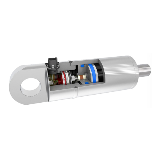
MH-Series DT Connector System Installation Manual 3. Product description and technology 3.4 Overview 1-piece version and 2-piece version 3.1 DT Connector type The new Temposonics MH-Series connector type is made especially for mobile hydraulic applications to connect Temposonics In-cylinder sensors with machine harnesses. It fits to the widely used Deutsch DT connector family. -
Page 6: Space Requirements - Conditions, Design (By The Example Of Mh Type Sensor)
MH-Series DT Connector System Installation Manual 4. Space requirements – conditions, design (by the example of MH type sensor) 4.1 DT connector dimensions, 1-piece version 39,2 18,3 20,3 Fig. 4: DT connector dimensions, 1-piece version MTS Steckersystem DT 1teilig T. Schmale April 2021 Schutzvermerk nach ISO 16016 GEZEICHNET... -
Page 7: Dimensions Of Related Bore Holes And Tolerances, 1-Piece Version
MH-Series DT Connector System Installation Manual 4.2 Dimensions of related bore holes and tolerances, 1-piece version 32,0 + 0,1 18H8 Fig. 6: Dimensions of related bore holes and tolerances, 1-piece version T. Schmale Januar 2021 Schutzvermerk nach ISO 16016 GEZEICHNET BG Zyl+Stecker DT 1teilig final Weitergabe sowie Vervielfäl�gung dieses Dokuments, Verwertung und... -
Page 8: Mounting
MH-Series DT Connector System Installation Manual 5. Mounting 5.1 Mounting sensor with DT Connectors – 1-piece version Sensor equipped with 1-piece DT connector and cylinder Insert the sensor into the cylinder and guide the Temposonics Interconnect through the hole in the cylinder-wall carefully Push the sensor housing into its seat and pull the Temposonics Interconnect out. - Page 9 MH-Series DT Connector System Installation Manual Take the new Temposonics DT connector 1-piece version and… …connect it to the Temposonics Interconnect …connect it to the Temposonics Interconnect Push the Temposonics DT Connector into its seat and rotate to the desired angle. Take care to NOT harm, squeeze or damage the wires Fig.
- Page 10 MH-Series DT Connector System Installation Manual Take the DT Connector Retainer and the tool Using a rubber mallet, gently drive the DT Connector Retainer into its seat until the flat area of the locking ring is flush with the flange of the connector, and the connector flange flush to the flat surface of the bore hole inside the cylinder wall Fig.
- Page 11 MH-Series DT Connector System Installation Manual After installation of DT Connector and DT Connector Retainer the assembly should look like this: Fig. 10: Mounting sensor with DT connector – 1-piece version, part 4...
-
Page 12: Mounting Sensor With Dt Connector - Fixation Via Screws
MH-Series DT Connector System Installation Manual 5.2 Mounting sensor with DT Connector - fixation via screws Follow the installation steps as descript on the pages above and put the sensor and the connector in place. The screw fixation method can get applied to both 1 and 2-piece connector version. Fig. - Page 13 MH-Series DT Connector System Installation Manual Apply 3 screw metric M4 and add a bolt adhesive against loosing. Tighten the screws according to the recommended torque (~ 2.5…3 Nm). Fig. 12: Mounting sensor with DT Connector - fixation via screws, part 2...
-
Page 14: The Mounting Tool
MH-Series DT Connector System Installation Manual 5.3 The mounting tool To press in the DT Connector Retainer correctly it is necessary to use a tool with dimensions as shown below. Only with this geometry it is guaranteed that the locking ring gets fixed properly. Tool for Crown Washer DT Fig. -
Page 15: Cylinder Handling After Sensor And Connector Installation
MH-Series DT Connector System Installation Manual 6. Cylinder handling after sensor and connector installation 6.1 Washing and drying of cylinders with installed sensors and DT Connectors During washing and drying procedure it is necessary to protect the DT Connector respectively its DT Connector Insert by a sealing cap. By these caps it is avoided that the contact pins get in contact to acid chemicals or corrosion causing agents. -
Page 16: Painting Cylinders With Installed Sensors And Dt Connector
MH-Series DT Connector System Installation Manual 6.2 Painting cylinders with installed sensors and DT connector 6.2.1 Wet painting At standard wet painting processes the DT connector system has to get protected too. Temposonics recommends to apply at least a sealing cap like shown above. - Page 17 MH-Series DT Connector System Installation Manual 6.2.2 Electrostatic painting • The thread of the protective cap must be clean and free from paint particles and other substances at all times. Various dry and wet methods of applying paint to the component •...
- Page 18 MH-Series DT Connector System Installation Manual A-A ( 1 : 1 ) X ( 5 : 1 ) B-B ( 1 : 1 ) Ø 19 Drawing created P.02 F.Gruenewald 26.11.2020 Y ( 5 : 1 ) Description changed by change date released by release date...
- Page 19 © 2023 Temposonics, LLC – all rights reserved. Temposonics, LLC and Temposonics GmbH & Co. KG are subsidiaries of Amphenol Corporation. Except for any third party marks for which attribution is provided herein, the company names and product names used in this document may be the registered trademarks or unregistered trademarks of Temposonics, LLC or...
Need help?
Do you have a question about the Temposonics DT Connector System and is the answer not in the manual?
Questions and answers