Table of Contents
Advertisement
Quick Links
Advertisement
Table of Contents
Troubleshooting

Related Manuals for Clarke GRIZZLY


Summary of Contents for Clarke GRIZZLY
- Page 1 INSTRUCTION MANUAL AND PARTS LIST GRIZZLY ® ULV SPRAYER REV. v 2.5.210...
-
Page 3: Table Of Contents
Warranty Information ........1 Clarke Grizzly Specifications ......2 Forward . - Page 4 TABLE OF CONTENTS GRIZZLY ULV SPRAYER ® Rotary Switch ..........23 Buttons .
- Page 5 TABLE OF CONTENTS GRIZZLY GRIZZLY ULV SPRAYER ULV SPRAYER ® ® Troubleshooting ........41 Warning Signals .
-
Page 6: Warranty Information
® Warranty Information Clarke Engineering Technologies, Inc. (CETI) warrants that during the first year following the purchase of CETI manufactured products or equipment, such products or equipment will perform in accordance with the instruction manuals when properly installed, operated and maintained. During the warranty period, CETI's sole obligation and liability shall be at CETI's option to: A. -
Page 7: Clarke Grizzly Specifications
MAKE IT CONVENIENT FOR YOU IN THE FUTURE, AS THIS INFORMATION MUST BE GIVEN WHEN ORDERING PARTS. Every effort has been made to make this manual as complete as possible so that it will provide maximum assistance in operating and maintaining your CLARKE Grizzly Cold Aerosol Fog Generator. -
Page 8: Forward
Before attempting to start your unit the first time, study the complete Operation Instructions carefully and identify all parts referred to. You will find that the operation of your CLARKE Grizzly Cold Aerosol Fog Generator is a simple matter. However, like all mechanical equipment, your unit requires a certain amount of maintenance. -
Page 9: Safety
ULV SPRAYER ® ® WARNING THIS CLARKE GRIZZLY COLD AEROSOL FOG GENERATOR IS MANUFACTURED AND SOLD FOR USE ONLY WITH INSECTICIDES WHICH HAVE BEEN DULY REGISTRATED AND APPROVED. DO NOT EXCEED THE DOSAGE SET FORTH ON THE REGISTRATION LABEL OF THE INSECTICIDE TO BE USED. -
Page 10: Description
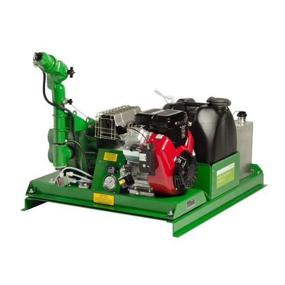
(ULV) application of insecticide. Description The CLARKE Grizzly Cold Aerosol Fog Generator consist of an engine with a fuel tank, a rotary blower capable of developing 10 P.S.I. maximum pressure, an adjustable discharge nozzle head assembly, a flow control, an insecticide tank, a flush tank, a remote cab control and a filter-silencer... -
Page 11: Theory Of Operations
There are too many variables involved, such as chemical mixture, flow rate and the temperature of the insecticide. Your Clarke representative or distributor can work with you to be sure you are producing the correct particle size for the insecticide used. -
Page 12: Assembly Instructions
® Assembly Instructions The CLARKE Grizzly Cold Aerosol Fog Generator is shipped completely assembled except that the Remote Control Box needs to be plugged into the socket located on the fog generator, see Figure 1, and The other end of the cable plug into the end of the pump box, see Figure 2 (See page 8). - Page 13 OPERATION GRIZZLY GRIZZLY ULV SPRAYER ULV SPRAYER ® ® Figure 2- Remote Socket Connection on Pump Box...
- Page 14 ULV SPRAYER ® In order to eliminate vibration and excessive cab noise, the CLARKE Grizzly Cold Aerosol Fog Generator should be bolted to the bed of the vehicle, see Figure 3. Position the fog generator so that the nozzle is located towards the rear of the vehicle and all switches are easily accessible. Make sure that the fog generator is located where the insecticide tank can be easily filled.
- Page 15 Mount the small enclosure in the cab of the vehicle in a convenient location. Route the cables back to the CLARKE Grizzly Cold Aerosol Fog Generator in a way that affords protection against cutting and snagging. Plug the cable in and hand tighten the locking cap onto the socket.
-
Page 16: Pre-Start
Read this complete OPERATION INSTRUCTIONS section before starting the CLARKE Grizzly Cold Aerosol Fog Generator. When operating the CLARKE Grizzly Cold Aerosol Fog Generator for the first time, move to an uncongested and well-ventilated work area in an open area away from flammable materials. - Page 17 OPERATION GRIZZLY GRIZZLY ULV SPRAYER ULV SPRAYER ® ® 7. Service the insecticide tank with the appropriate insecticide. Always use a funnel with a strainer screen when adding insecticide to the tank. Reference Figure 6. 8. Place flushing solution in the flush tank. ReferenceFigure 6.
-
Page 18: Start-Up
OPERATION GRIZZLY ULV SPRAYER ® Start-Up 1. On the Remote Control Box, turn the Main Power switch to the ON position. Reference Fig- ure 4. 2. On the Remote Control Box, set the Spray switch to the OFF position. Reference Figure 4. -
Page 19: Low Pressure Cut-Off
Figure 8- Pressure Gauge Panel Low Pressure Cut-Off The CLARKE Grizzly Cold Aerosol Fog Generator is equipped with an air low-pressure cut-off switch. If, for some reason, the nozzle air pressure drops below 1 P.S.I., the Flow Control will cut off. -
Page 20: Smart Flow Control
Installation, Operation and Maintenance Manual Description The Smart Flow control provides programmable microcomputer control for Clarke spraying systems. The Smart Flow control offers the following features: • The Smart Flow control uses data from speed and flow sensor to vary the speed of the electric pump on the spraying system. -
Page 21: Total Counters
SMARTFLOW MANUAL GRIZZLY GRIZZLY ULV SPRAYER ULV SPRAYER ® ® Console SmartFlow SmartFlow Tech Support: 1-800-859-2847 Engineering Technologies, Inc. POWER ON Gal / 1000 SPEED FLOW PER MINUTE Lbs N / Ac Electric Pump AREA TOTAL FLOW Gal / Ac... -
Page 22: Control Panel Functions
SMARTFLOW MANUAL GRIZZLY ULV SPRAYER ® Control Panel Functions This section describes the functions of the control panel for the Smart Flow control. The control panel is the same for gas and electric spraying systems, except for the three controls on the lower left. -
Page 23: Alarm
SMARTFLOW MANUAL GRIZZLY GRIZZLY ULV SPRAYER ULV SPRAYER ® ® Alarm An audible alarm (beeper) sounds when there is an error. The warning LED and ERROR indicator in the upper display window will also be lit. Warning LED The warning LED is lit when there is an error. The alarm will sound and the ERROR indicator in the upper display window will also be lit. -
Page 24: Power Switch
SMARTFLOW MANUAL GRIZZLY ULV SPRAYER ® POWER Switch The POWER switch turns the Smart Flow control on and off. In the OFF position, this switch also grounds the magneto on a gas spraying system or trips the main breaker on an electric spraying system. -
Page 25: Display
SMARTFLOW MANUAL GRIZZLY GRIZZLY ULV SPRAYER ULV SPRAYER ® ® Display The display is used to view current values and calibration values. The display has three windows: • Upper window • Left window • Right window Upper Window Gal / 1000... -
Page 26: Upper Window
SMARTFLOW MANUAL GRIZZLY ULV SPRAYER ® Upper Window The upper window of the display is used to view the application rate, units, and errors. Gal / 1000 Lbs N / Ac Gal / Ac kg / ha ERROR Rate 1 2 3... -
Page 27: Left Window
SMARTFLOW MANUAL GRIZZLY GRIZZLY ULV SPRAYER ULV SPRAYER ® ® Left Window The left window of the display is used to view error codes and pressure codes (when a pressure sensor is installed for a gas spraying system). CAL PSI bar... -
Page 28: Rotary Switch
SMARTFLOW MANUAL GRIZZLY ULV SPRAYER ® Rotary Switch The rotary switch is used to select the parameters to display and to set calibration values. The selected value is displayed in the right window of the display, along with the data indicator. - Page 29 SMARTFLOW MANUAL GRIZZLY GRIZZLY ULV SPRAYER ULV SPRAYER ® ® Control Description TIME* Displays the total spray time since the counter was last reset, in tenths of an hour. OFL indicates that the Time counter has exceeded 19999.9. Red: Calibration Positions TARGET RATE Displays the target application rate in ounces per acre or liters per hectare.
-
Page 30: Buttons
SMARTFLOW MANUAL GRIZZLY ULV SPRAYER ® Buttons The buttons are used to select the application rate, display the tank level and spray time, and reset the counters. MIN SPEED SPEED CAL TANK HOURS RESET RATE 1 RATE 2 RATE 3... -
Page 31: Gas Controls
SMARTFLOW MANUAL GRIZZLY GRIZZLY ULV SPRAYER ULV SPRAYER ® ® Gas Controls For a gas spraying system, the lower left controls are: START CHOKE FLUSH Control Description START switch Starts the gas engine. CHOKE switch Chokes the gas engine. FLUSH switch Flushes the spraying system. -
Page 32: Switch
SMARTFLOW MANUAL GRIZZLY ULV SPRAYER ® +/– Switch The +/– (increase/decrease) switch is used to enter or adjust values in the display. Mode Control Description VAR, CON or Press TANK button This switch adjusts the tank volume. See “Adjusting Tank OFF spray mode Volume”... -
Page 33: Spray Switch
SMARTFLOW MANUAL GRIZZLY GRIZZLY ULV SPRAYER ULV SPRAYER ® ® SPRAY Switch The SPRAY switch controls the spray mode. SPRAY CONT Control Description VAR position Variable Mode The Smart Flow control varies the pump speed to automatically maintain the selected application rate based on flow and speed. -
Page 34: Calibration
SMARTFLOW MANUAL GRIZZLY ULV SPRAYER ® Calibration This section covers these calibration topics: • Calibration Factors (page 30) • Entering Calibration Mode (page 31) • Exiting Calibration Mode (page 31) • Setting Continuous Speed (page 32) • Setting Units (page 32) •... -
Page 35: Calibration Factors
SMARTFLOW MANUAL GRIZZLY GRIZZLY ULV SPRAYER ULV SPRAYER ® ® Calibration Factors The Smart Flow control has eight calibration factors: Calibration Rotary Switch Description Factor Position Continuous Speed DISTANCE The speed that is used in Continuous mode. Units FLOW PER The control can be set to use English or Metric units. -
Page 36: Entering Calibration Mode
SMARTFLOW MANUAL GRIZZLY ULV SPRAYER ® Note: To view the first four factors in the previous table, you must place the control in Calibration mode. The last six factors can be viewed at any time by placing the rotary switch in one of the red positions. -
Page 37: Setting Continuous Speed
SMARTFLOW MANUAL GRIZZLY GRIZZLY ULV SPRAYER ULV SPRAYER ® ® Setting Continuous Speed To set the speed that is used in Continuous mode: 1. Place the control in Calibration mode. 2. Move the rotary switch to the DISTANCE position. SPEED is displayed in the upper display window, and the current Continuous Speed is displayed in the right display window. -
Page 38: Setting Target Application Rate
SMARTFLOW MANUAL GRIZZLY ULV SPRAYER ® Setting Target Application Rate To set one of the three preset Target Application Rates for Variable and Continuous mode: 1. Place the control in Calibration mode. 2. Move the rotary switch to the TARGET RATE position. -
Page 39: Setting Minimum Speed
SMARTFLOW MANUAL GRIZZLY GRIZZLY ULV SPRAYER ULV SPRAYER ® ® Setting Minimum Speed To set the minimum speed allowed in Variable mode: 1. Place the control in Calibration mode. 2. Move the rotary switch to the MIN SPEED position. Lo is displayed in the upper display window, and the current Minimum Speed is displayed in the right display window. -
Page 40: Setting The Flow Calibration Factor
SMARTFLOW MANUAL GRIZZLY ULV SPRAYER ® Setting the Flow Calibration Factor To set the Flow Cal factor: 1. Place the control in Calibration mode. 2. Move the rotary switch to the FLOW CAL position. The calibration flow amount (Cal Total Flow) is displayed in the upper display window, and the current Flow Cal factor is displayed in the right display window. - Page 41 SMARTFLOW MANUAL GRIZZLY GRIZZLY ULV SPRAYER ULV SPRAYER ® ® 2. calibrate smartflow to pump. a. get into cal mode. b. set the continious speed, swath width, and target rate 1 calibration factors. these will be used to operate the pump at the desired rate. ( example – 10 mph, 300 ft. swath width, and 2.5 ounces per acre.)
-
Page 42: Reloading Calibration Defaults
SMARTFLOW MANUAL GRIZZLY ULV SPRAYER ® Reloading Calibration Defaults Normally, the calibration settings that were in use when the Smart Flow control was turned off will be active when the control is restarted. However, you can reload the default calibration settings... -
Page 43: Operation
SMARTFLOW MANUAL GRIZZLY GRIZZLY ULV SPRAYER ULV SPRAYER ® ® Operation This section covers these operating procedures: • Startup (page 38) • Selecting the Application Rate (page 39) • Shutdown (page 39) • Clearing Counters (page 39) • Adjusting Tank Volume (page 40) •... -
Page 44: Selecting The Application Rate
SMARTFLOW MANUAL GRIZZLY ULV SPRAYER ® Selecting the Application Rate To select a preset application rate, press the desired rate button (RATE 1, RATE 2, or RATE 3). In the upper display window, the selected rate indicator is lit. If the SPRAY switch is in the VAR or CON position, the selected rate is displayed for three seconds. -
Page 45: Adjusting Tank Volume
SMARTFLOW MANUAL GRIZZLY GRIZZLY ULV SPRAYER ULV SPRAYER ® ® Adjusting Tank Volume You should adjust the tank volume to match the actual volume of liquid in your tank each time you fill the tank. To adjust the tank volume: 1. -
Page 46: Troubleshooting
TROUBLESHOOTING GRIZZLY ULV SPRAYER ® Troubleshooting This section covers these troubleshooting topics: • Warning Signals (page 41) • Error Codes (page 41) Warning Signals If an error occurs for more than one second, the following occur: • The warning LED is lit. -
Page 47: Maintenance
General • Replace worn or damaged parts on the CLARKE Grizzly Cold Aerosol Fog Generator. • Service the engine according to the Engine Maintenance Manual. The engine is equipped with a replaceable oil filter. Reference Figure 5. -
Page 48: Every 50 Hours
MAINTENANCE GRIZZLY ULV SPRAYER ® Every 50 Hours • Check the flow rate calibration. See Setting the Flow Calibration Factor (page 35) and Calibration Factors (page 30). • Check all bolts and fasteners and tighten if necessary. • Check all gasoline hoses, insecticide lines and fittings for cracks, leaks or wear. Replace if needed. -
Page 49: Every 100 Hours
MAINTENANCE GRIZZLY GRIZZLY ULV SPRAYER ULV SPRAYER ® ® Every 100 Hours • Clean the insecticide filter. If this filter becomes stopped up, the insecticide flow will be restricted or stopped. There is a fine mesh screen located in the cylindrical housing. This screen can be removed for inspection and/or cleaned by manually unscrewing the housing bowl. - Page 50 MAINTENANCE GRIZZLY ULV SPRAYER ® • Replace the in-line gasoline filter. Using pliers, loosen the tension on the two hose clamps and slide them off of the filter barbs. Remove the old filter from the gasoline hose. Install a new filter and replace the hose clamps.
-
Page 51: Engine
MAINTENANCE GRIZZLY GRIZZLY ULV SPRAYER ULV SPRAYER ® ® Engine Lubricate and service the engine according to the engine manual. We recommend the use of a high quality, SAE 30W detergent oil classified "for service SF, SG, SH" (such as Briggs & Stratton(r) 100005 or 100028) when operating at temperatures above 40∞... -
Page 52: Recommended Greasing Intervals
MAINTENANCE GRIZZLY ULV SPRAYER ® require more frequent changes. Every six months the oil breather plug should be removed cleaned in solvent and blown out with clean compressed air to provide unobstructed venting. Shaft bearings at the drive end of the blower are grease lubricated and each bearing housing is equipped with pressure type grease fittings and pressure type relief fittings. -
Page 53: Couplings
MAINTENANCE GRIZZLY GRIZZLY ULV SPRAYER ULV SPRAYER ® ® Couplings To replace the engine, blower coupling, coupling sleeve or rubber sleeve: 1. Disconnect the negative(black) battery cable on the battery. 2. Remove the coupling guard cover. (4 screws, internal washers) 3. - Page 54 MAINTENANCE GRIZZLY ULV SPRAYER ® 5. Remove blower from the mainframe(4 nuts, bolts, lock washers). Carefully remove rust, dirt, burrs, etc. from both engine and blower shafts using a file or emery cloth. 6. Take the engine coupler halve and place a 1” bushing into the center of the coupler aligning the 3 open holes.
- Page 55 MAINTENANCE GRIZZLY GRIZZLY ULV SPRAYER ULV SPRAYER ® ® 11. Check angular alignment with micrometer, vernier, or caliper. Measure from the outside of the one flange to outside of the other at intervals around the edge of the coupling flanges. Determine the maximum and minimum dimensions without rotating the flange couplings.
-
Page 56: Storage
® Storage Before storing the CLARKE Grizzly Cold Aerosol Fog Generator after use or if it is to be idle for any appreciable length of time, the following preparations should be made: 1. Flush the fog generator for at least 10 minutes. - Page 57 11. Clean all insecticide residue and oil off the CLARKE Cougar Cold Aerosol Fog Generator and repaint if necessary. 12. Store the CLARKE Cougar Cold Aerosol Fog Generator in a clean dry area under suitable cover protected from the elements.
- Page 58 Notes GRIZZLY ULV SPRAYER ®...
-
Page 59: Spare Parts
PARTS BOOK - TABLE OF CONTENTS GRIZZLY GRIZZLY ULV SPRAYER ULV SPRAYER ® ® Page Description Part No. 55 - 58 MAIN ASSEMBLY ........................12208 OHV 55 - 58 ENGINE ASSEMBLY (No Part Brarkdown)................12788 55 - 58 FLUSH TANK ASSEMBLY..................... -
Page 60: Main Assembly
MAIN ASSEMBLY GRIZZLY GRIZZLY GRIZZLY ULV SPRAYER ULV SPRAYER ULV SPRAYER ® ® ®... - Page 61 MAIN ASSEMBLY GRIZZLY GRIZZLY GRIZZLY ULV SPRAYER ULV SPRAYER ULV SPRAYER ® ® ® Pos Qty. Description Part No. GAS TANK 12 GALLONS ...................... 10209 1/4" X 1/4" 90˚ MALE ELBOW HOSE BARB ................. 10328 50" 1/4" GAS LINE ........................
- Page 62 MAIN ASSEMBLY GRIZZLY ULV SPRAYER ®...
- Page 63 MAIN ASSEMBLY GRIZZLY GRIZZLY GRIZZLY ULV SPRAYER ULV SPRAYER ULV SPRAYER ® ® ® Pos Qty. Description Part No. PICK-UP TUBE ........................10336 STRAP ASSEMBLY ....................... 10321 MOUNTING BRACKET, FLUSH TANK ................. 10086 FLOW CONTROL ASSEMBLY(SEE “PUMP BOX ASSEMBLY” on page 69).......
-
Page 64: Blower Assembly
BLOWER ASSEMBLY GRIZZLY ULV SPRAYER ® 15 14 40 38... - Page 65 BLOWER ASSEMBLY GRIZZLY GRIZZLY GRIZZLY ULV SPRAYER ULV SPRAYER ULV SPRAYER ® ® ® Pos Qty. Description Part No. SWIVEL ASSEMBLY ......................10312 STUD KNOB ASSEMBLY ...................... 10402.1 SWIVEL HALF INLET ......................10173 SWIVEL HALF OUTLET ......................10269 SNAP RING STAINLESS STEEL ..................
- Page 66 BLOWER ASSEMBLY GRIZZLY ULV SPRAYER ® 15 14 40 38...
- Page 67 BLOWER ASSEMBLY GRIZZLY GRIZZLY GRIZZLY ULV SPRAYER ULV SPRAYER ULV SPRAYER ® ® ® Pos Qty. Description Part No. BUSHING 2 1/2" X 2" ......................10733 BLOWER..........................10208 LOCKNUT 2 1/2"........................10200 AIR FILTER ..........................12021 AIRCLEANER ASSEMBLY INCLUDES 52................
-
Page 68: Nozzle Assembly
NOZZLE ASSEMBLY GRIZZLY ULV SPRAYER ® *Item 24 is not included with harness assembly... - Page 69 NOZZLE ASSEMBLY GRIZZLY GRIZZLY GRIZZLY ULV SPRAYER ULV SPRAYER ULV SPRAYER ® ® ® Pos Qty. Description Part No. NOZZLE ASSEMBLY INCLUDES ITEMS 2-13 ..............10314.2 NOZZLE BODY ........................10271 PHILLIPS PAN HEAD SCREW 10 - 32 X 3/8"............... 11145Z DIFFUSER CONE ........................
-
Page 70: Chemical Tank Assembly
CHEMICAL TANK ASSEMBLY GRIZZLY ULV SPRAYER ®... - Page 71 CHEMICAL TANK ASSEMBLY GRIZZLY GRIZZLY GRIZZLY ULV SPRAYER ULV SPRAYER ULV SPRAYER ® ® ® Pos Qty. Description Part No. CHEMICAL TANK ASSEMBLY....................10296 PICK UP TUBE ASSEMBLY ....................10298 3/8" X 1/4" 90˚ FEMALE ELBOW INCLUDES 3/8" NUT #10539 ...........
-
Page 72: Pump Box Assembly
PUMP BOX ASSEMBLY GRIZZLY ULV SPRAYER ® Items 5,6,14 & 15 not included with pump assembly... - Page 73 PUMP BOX ASSEMBLY GRIZZLY GRIZZLY GRIZZLY ULV SPRAYER ULV SPRAYER ULV SPRAYER ® ® ® Pos Qty. Description Part No. PUMP ASSEMBLY......................... 10344 PUMP ............................. 10177 1/4" X 1/4" X 90˚ MALE ELBOW INCLUDES 1/4" NUT #10538 ..........10038 3/8" X 1/4" X 90˚ MALE ELBOW INCLUDES 3/8" NUT #10539 ..........
-
Page 74: Gauge Panel Assembly
GAUGE PANEL ASSEMBLY GRIZZLY ULV SPRAYER ® 15 7 16 17... - Page 75 GAUGE PANEL ASSEMBLY GRIZZLY GRIZZLY GRIZZLY ULV SPRAYER ULV SPRAYER ULV SPRAYER ® ® ® Pos Qty. Description Part No. COUPLING COVER....................... 12784 10 - 32 X 3/8" PHILLIPS PAN HEAD SCREW............... 11145Z #10 INTERNAL LOCK WASHER ................... 11102Z 6 - 32 X 3/8” PHILLIPS PAN HEAD SCREW .................
-
Page 76: Engine Panel Assembly
ENGINE PANEL ASSEMBLY GRIZZLY ULV SPRAYER ® Pos Qty. Description Part No. PANEL, ENGINE ASSEMBLY ....................12637 ENGINE PANEL, WITH DECAL .................... 12636 START BUTTON ASSEMBLY ....................12768 STOP SWITCH ASSEMBLY ....................12767 12" LOAM (NOT SHOWN) ......................10046... -
Page 77: Choke Assembly
CHOKE ASSEMBLY GRIZZLY GRIZZLY GRIZZLY ULV SPRAYER ULV SPRAYER ULV SPRAYER ® ® ® Pos Qty. Description Part No. LINKAGE ROD, CHOKE ......................12766 SCREW 8-32 X 1/4” PHILLIPS PAN HEAD ................11084Z COIL SUB ASSEMBLY ......................12742 SPRING PIN 3/32 X 1/2” ...................... -
Page 78: Trouble Shooting
TROUBLE SHOOTING GRIZZLY ULV SPRAYER ® TROUBLE POSSIBLE CAUSE REMEDY Air blast at nozzle but no pres- Defective pressure gauge. Replace. sure showing on pressure gauge. Air leaks in the air line between Replace air line or reconnect if the nozzle and the pressure loose. - Page 79 TROUBLE SHOOTING GRIZZLY GRIZZLY GRIZZLY ULV SPRAYER ULV SPRAYER ULV SPRAYER ® ® ® TROUBLE POSSIBLE CAUSE REMEDY Cannot calibrate to correct parti- Air pressure too low, which will Increase engine speed. cle size. produce large particles. Air pressure too high, which will Decrease engine speed.
- Page 80 TROUBLE SHOOTING GRIZZLY ULV SPRAYER ® TROUBLE POSSIBLE CAUSE REMEDY Chemical pump not running Defective Spray switch or loose Replace. when Spray switch is turned on. connectors. Defective Low-Pressure Cut-Off Replace. For field repair, this switch. switch can be “jumped” by con- necting a wire between the ter- minals on the switch.
- Page 81 TROUBLE SHOOTING GRIZZLY GRIZZLY GRIZZLY ULV SPRAYER ULV SPRAYER ULV SPRAYER ® ® ® TROUBLE POSSIBLE CAUSE REMEDY Engine backfires. Gasoline mixture too lean. Check carburetor. Defective spark plugs. Clean, adjust and/or replace. Inlet valves sticking. Free, clean and adjust valve.
- Page 82 TROUBLE SHOOTING GRIZZLY ULV SPRAYER ® TROUBLE POSSIBLE CAUSE REMEDY Engine hard to start, will not Main Power switch located on Place switch in ON position or start or fails. remote control box in OFF posi- replace faulty switch and/or tion or faulty switch and/or wires.
-
Page 83: Electrical Schematic
ELECTRICAL SCHEMATIC GRIZZLY GRIZZLY GRIZZLY ULV SPRAYER ULV SPRAYER ULV SPRAYER ® ® ® NOZZLE SOLENOID CHOKE SOLENOID REMOTE MAGNETO KILL SWITCH START SWITCH START SOLENOID BROWN FLUSH YELLOW PRESSURE OK + BATTERY (SWITCHED) BLUE + BATTERY (SWITCHED) CHOKE SOLENOID...
Need help?
Do you have a question about the GRIZZLY and is the answer not in the manual?
Questions and answers