Advertisement
Quick Links
Advertisement

Related Manuals for Schwinn Z


Summary of Contents for Schwinn Z
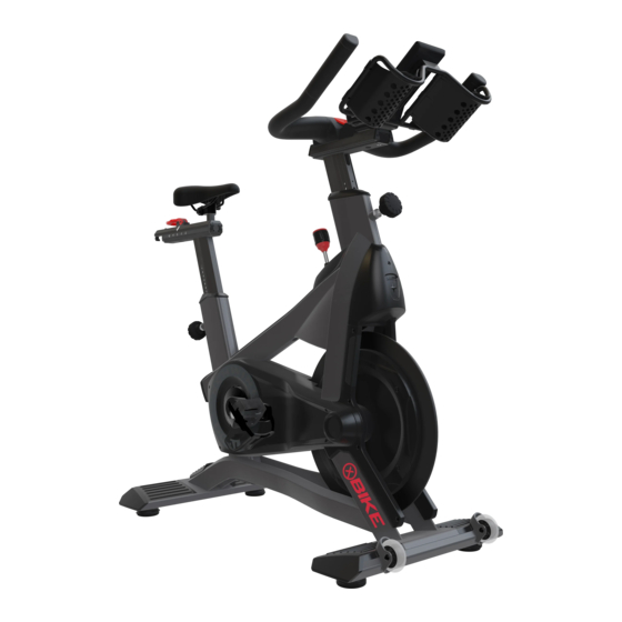
- Page 1 CORE HEALTH & FITNESS Z/X BIKES OWNER'S MANUAL...
- Page 2 TABLE OF CONTENTS IMPORTANT SAFETY INSTRUCTIONS ........................4 IMPORTANT LABEL LOCATIONS ........................5 PRODUCT SPECIFICATIONS ........................5 OPERATIONS ..............7 ASSEMBLY ........................8 REQUIRED TOOLS ..............8 ASSEMBLY PARTS ..............9 PROCEDURE ..............10 FIRST TIME SETUP ........................17 AFTER THE INSTALL ........................19 CONSOLE FEATURES ........................21 BLUETOOTH PAIRING PRIORITY ...............
- Page 3 ........................43 SEAT POST ASSEMBLY ..............43 HANDLE BAR ASSEMBLY ..............43 TRAPEZOIDAL LOCK NUT ..............44 END CAP KIT ..............44 BRAKE CHANGE ..............45 REPLACEMENT PARTS ........................46 9-7520 - SCHWINN Zs ..............46 SUPPORT & SERVICE ........................51 Page 3...
- Page 4 Do not use DANGER: Pedals that have not been attachments not recommended by Core Health tested and qualified by Schwinn should never & Fitness. Fig. 1 Required Clearance be used on Schwinn bikes. Unqualified pedals 4.
- Page 5 IMPORTANT LABEL LOCATIONS This page shows the location of the warning labels and communication stickers placed on the equipment as part of the manufacturing process. It is critical that owners maintain the integrity and placement of these stickers. If you find any stickers missing or damaged the replacement numbers are shown on the support site and following pages. See Support and Service to order replacements.
- Page 6 LABEL, WARNING, FRENCH, UNIVERSAL CYCLE STICKER, FORE/AFT, HBAR SLIDER, UGC 050-5727 000-0096 050-5896 LABEL, BELT IDLER TORQUE, TIMING SCHWINN QUALITY BADGE, 40 MM LABEL,WARNING, MEDICAL, HBAR V2 050-5794 *(9-7510 Only) 050-5795 *(9-7520 Only) DECAL, FORK, Zs, V2 DECAL, FORK, Za, V2...
- Page 7 OPERATIONS Fig. 3 Fig. 4 Adjusting Brake Knob Adjusting Seat Post or Handlebar Post height with Locking Pop Pin Emergency Stop 14. Turn pop-pin counterclockwise and pull to loosen. Press down on the emergency stop handle. 15. While having the pop-pin pulled out, adjust the seat or handlebar tube to desired height. Adjusting the Resistance Do not lift the seat post or handlebar posts above the STOP mark on the tube.
- Page 8 ASSY, FOOT, REAR 050-5831 HANG TAG, UGC, BATTERY CHARGE/QR CODE 740-9537-XX ASSY, FOOT, FRONT, NEXT GEN BIKE 718-6334 UGC V2.0, BLISTER PACK, Z BIKE 7520-XXXXP0 BIKE, SCHWINN GROUP CYCLE, Za 620-8789 OWNERS MANUAL, SCHWINN, UGC 740-9020 ASSY, SET, PEDALS, S5/S7...
- Page 9 STOPPER, F/A, HBAR, ACPU 727-0253 CAP, LOWER, BAR SLIDER V2.2 727-0310 END CAP, SEAT POST, UGC 740-8247 THREADED PLATE, FEET, BLADE 740-8607 CALIBRATION TOOL, ZERO POINT, ACPP 740-8145 BOLT, CRANKARM, M8 718-6334 UGC V2.0, BLISTER PACK, Z BIKE Page 9...
- Page 10 After assembly, a complete visual inspection, and test of the features and functions of the assembled unit must be made prior to use. Please note that while the install images show the Z Bike, these instructions are also valid for the X Bike.
- Page 11 2. Install the stopper into the handlebar post, then use a 4mm allen key to secure to stopper inside the post using one (1) M6 x 30mm flat head machine screw. 718-6110 727-0290-XX 110-3507 Fig. 10 3. Use a phillips head screwdriver to secure the handlebar post end cap using four (4)
- Page 12 X Bikes SKIP THIS STEP 4. Plug the console cable into the console. Fig. 12 5. Engage the handlebar fore/aft adjustment lever to lock the handlebars in place. Fig. 13 Page 12...
- Page 13 6. Tip the bike forward onto the handlebars. Put a blanket or the shipping box between the floor and handlebars to prevent damage. BLANKET OR SHIPPING BOX Fig. 14 740-8247 7. Install one (1) threaded 740-9537-XX plate into the frame, then use a torque wrench with a 13mm socket to secure the...
- Page 14 9. Lift the fore/aft adjustment lever on the seat slider assembly. 10. Slide the seat slider assembly onto the seat post. 727-0286 Fig. 16 11. Install the stopper into the seat post, then use a 4mm allen key to secure to stopper inside the post using one (1) M6 x 30mm flat head machine...
- Page 15 12. Use a phillips head screwdriver to secure the seat post end cap using two (3) M2.9 x 10mm pan head machine screws. 727-0310 110-4343 Fig. 18 13. Engage the fore/aft adjustment lever on the seat slider assembly. Fig. 19 Page 15...
- Page 16 14. Install the left pedal into the left crank arm. 15. Hand-thread the M8 pedal bolt through the crank arm and into the 740-8145 pedal. 16. Use a torque wrench with an 8mm allen socket to torque the pedal bolt to 37 ft-lb (50 Nm).
- Page 17 FIRST TIME SETUP To watch this procedure scan or visit: QR.COREHANDF.COM/ZXFTS 718-5627-XX Fig. 22 Once the bike is fully assembled, move it into the ride location, then adjust the four (4) leveling feet located on the front and rear stabilizers to level the bike and ensure it does not move or wobble during the ride.
- Page 18 Select your bike Update Features and Firmware (black if Enter Settings Connect available) Fig. 24 Fig. 25 Fig. 26 Calibrate the Power Tap the buttons simultaneously then tap the button to enter the Service Menu. Press the button until 4iiii CAL is shown in the message center then press the button to begin the pairing process.
- Page 19 AFTER THE INSTALL Test the full range of motion of the seat post assembly including Test the full range of motion of the handle bar post assembly fore/aft and height adjustments as well as smooth operation of the including fore/aft and height adjustments as well as smooth fore/aft adjustment lever and pop pin.
- Page 20 Rhythm Mode and accelerate RPM through green-yellow-orange-red zones on the Zone Meter. Confirm that fork LED’s match the Zone Meter color throughout. 10. Remove film from Schwinn Quality beauty ring Fig. 32 Fig. 33 Page 20...
- Page 21 CONSOLE FEATURES Fig. 34 To turn on console, press any button or start pedaling. Console enters PAUSE mode when pedaling stops, and the message center shows the option to END? Either press the corresponding button above or wait the TIMEOUT duration selected in the Service Menu to enter SUMMARY mode, or continue pedaling to resume workout.
- Page 22 Description Function Allows Custom values to be set for FTP and Max HR Personalization Button Allows Pairing of HR Strap and/or App UP/DOWN Buttons Allows for selection of message center options on various screens tap-to-pair Apple and Samsung watches (NFC only, not other HR monitors or apps). You may need to set your watch to Detect Gym Equipment, and accept the connection to start a workout.
- Page 23 Note: Only a Bluetooth HR Device can be paired with another device. When connecting, the console will look for devices in the order of the list. Pairing with Apple Watch : The Z console has the capability to connect using Near Field Communication (NFC) with Apple Watch (must be running WatchOS 4.2 or later and have option Detect Gym Equipment set to On in Watch settings for Workout App.) When an Apple Watch is connected, the...
- Page 24 BEFORE EACH RIDE BLINKS FOR 30 SEC TAP FOR PERSONALIZATION TAP TO CHANGE MODE TAP TO PAIR Fig. 35 Shown on Wake CHANGING MODES Unless values are changed in the Service Menu, the console wakes in reduced mode with no zone meter, trophies, or fork LEDs (See Fig.
- Page 25 Tap the button twice to personalize Max Heart Rate • Default MAX HR value is shown in the message center (change in the Service Menu) • Press the buttons to increase or decrease value by 1 or hold to increase or decrease by 5 every 0.5 seconds.
- Page 26 FTP CALCULATION USING TROPHIES BLINKS APPROACHING PREVIOUS BEST Fig. 37 Trophies If the 1, 5, or 20 MIN icon is flashing, that means you’re approaching a new best power. • At the end of 5 minutes, multiply that 5MIN value by 0.85 for your new FTP •...
- Page 27 DISTANCE CHALLENGE CURRENT COLUMN ACTIVE ROW POWER Fig. 38 Distance Challenge Tap the button. Perform the CURRENT interval for a prescribed time duration ( on active row) Tap the button again to freeze the data in the CURRENT column Observe power ( on row) or distance ( on row) At any time tap...
- Page 28 EXTRACTING DATA AFTER A RIDE Upload data from the console to your USB drive The ride data file is a great tool for people to track their rides and see their progress. After ride is complete you may save ride data from the console to a USB stick. Insert USB stick into console port.
- Page 29 SERVICE MENU The Service Menu (previously called MAINTENANCE mode) allows access to service and diagnostic information, as well as provides the ability to adjust certain program default parameters. To enter the Service Menu: Tap the buttons simultaneously then tap the button to enter the Service Menu.
- Page 30 Place the file on the root drive of a blank USB drive. Begin pedaling on the bike to wake the console. Console must be powered until process is complete. On the Z console, tap the buttons simultaneously then tap button to enter the Service Menu.
- Page 31 UPDATING GEM MODULE Required Tools: • iOS Device (iPhone or iPad) w/ConfigurEZ app Open the ConfigurEZ app, and tap on the “i” Tap the “Login” button to log in to the updater If you receive a prompt about verifying the icon to open the settings menu.
- Page 32 Select “beta” from the Release Channel drop Press the “Scan” button in the upper right 10. On the Z console, Tap the buttons down menu corner. simultaneously then tap the button to enter the Service Menu. Select “v2.4.5” from the Version drop down menu 11.
- Page 33 OWNER’S CUSTOMIZATION Fig. 53 Lock Modes If you are a Rhythm-Only, Power-Only, or Heart Rate-Only studio, you are able to set the mode that the console wakes up in and not allow the member to change the mode with the ENTER button: Tap the buttons simultaneously then tap the button to enter the Service Menu.
- Page 34 GENERAL CONSOLE PROCEDURES RESETTING THE CONSOLE Console resets to values in the Service Menu when it enters IDLE mode. Button can be pressed to immediately reset the console. PAIRING A NEW 4iiii POWERMETER via ANT+ For Bluetooth pairing instructions, please see “BLUETOOTH VS. ANT+ CONNECTION” on page In the event a new crank needs to be paired with the console the below procedure will pair a new crank.
- Page 35 I DON’T SEE MY HEART RATE To troubleshoot a missing heart rate: • Check the MaxHR setting in the Service Menu (factory default is 185) to determine the minimum bpm that 1. Confirm that you are wearing your heart rate monitor, that it is will activate green = 0.60 x MaxHR and/or press the charged, and has clean contact with your skin.
- Page 36 POWER READS HIGH OR LOW/CALIBRATING POWER The Powermeter measures the 3-dimensional deflection of the left crank due to the force exerted into the pedal, the same technology used in outdoor cycling. It is a result of resistance applied and pedal speed, but because a pedal stroke is cyclical, the force is averaged over 3 seconds.
- Page 37 Go Back. Calibrate via 4iiii app if power Select Calibrate in the app appears low or high Fig. 59 Fig. 60 Follow the directions (point left crank straight down to 6 o’clock) and tap crank image. 10. To continue to calibrate other bikes, “forget”...
- Page 38 CONSOLE ERROR MESSAGES During normal operation the following errors may be shown on the console: ERROR On Menu Cause Resolution PASSCODE has been turned on in WRONG PASS! MM Password the Service Menu and wrong password Enter correct passcode has been entered. Console cannot find a compatible NOTHING FOUND HR Pairing...
- Page 39 EXPLANATION AND FUNCTION OF GEARS WHAT IS A GEAR? • A “Gear” is a measure of resistance on a numbered scale. HOW ARE GEARS CALCULATED? • Gears are derived from a triangulation of data from the angle sensor, power meter torque value, and RPM from the RPM sensor.
- Page 40 BLUETOOTH VS. ANT+ CONNECTION ANT+ Traditionally, ANT+ has been the default method of communication between the crank and console. However, as technology has advanced and studio environments have evolved, there is a possibility that the ANT+ connection may be disrupted in certain settings. Indicators of ANT+ Communication Interference: •...
- Page 41 MAINTENANCE TOOLS Working on this product will require basic and/or sometimes specialty tools based on the type of service that will be performed at any time. To assist, we recommend having the tools listed available when performing maintenance. • Metric Allen Key Set •...
- Page 42 Preventive Maintenance Cautions • While maintaining equipment you will want to avoid spraying any liquids directly onto any surface of the unit. Always spray cleaning solutions onto a clean towel first then wipe the unit. • Do not use glass cleaners or any other household cleaners on the console. The console should be cleaned with a damp cloth and dried on a daily basis. Cleaning solutions can be made of a 5:1 dilution ratio, where 5 parts water are mixed with 1 part of Simple Green®, Fantastik®, or 409®.
- Page 43 ABOUT THE BIKE In August of 2023, the seatpost and handlebar assemblies of the Schwinn X and Z bikes were updated to improve functionality. The previous designs were discontinued and are no longer available. Please see below for additional details.
- Page 44 TRAPEZOIDAL LOCK NUT The trapezoidal lock nut has also been updated to improve function. If the bike has the REV A trapezoidal lock nut, the lock nut kit will need to be ordered: 727-0277- KT “CLAMP PLATE REPLACEMENT KIT, UGC.” Fig.
- Page 45 BRAKE CHANGE In November of 2023, a change to the brake was made to improve function. If replacing the brake, check to see if the brake spacer is present by pressing down on the brake knob and inspecting the front of the brake. If the brake does NOT have the spacer, the entire brake assembly will need to be replaced: 727-0294. If the brake spacer is present, the brake itself can be replaced: 727-0293.
- Page 46 050-5828 LABEL, WARNING, ENGLISH, UGC 718-6316 KIT, HBAR SLIDER WPOST, UGC 050-5829 LABEL, WARNING, FRENCH, UNIVERSAL CYCLE 718-6334 UGC V2.0, BLISTER PACK, Z BIKE 050-5896 LABEL,WARNING, MEDICAL, HBAR V2 727-0121 STRIP, HANDLEBAR POST, ACPU 050-5897 STICKER, FORE/AFT, SEAT, RIGHT, UGC...
- Page 47 727-0294 + 727-0293 only valid for bikes 718-6215 made AFTER 11/12/23 731-1958 80044 110-3730 740-7613 120-3403 001-0764 120-3486 727-0294 718-6306 727-0293 003-1508 740-9517 718-6131 050-5724 740-8145 740-7614 740-9020 110-3640 Fig. 70 Brake Fig. 71 Cranks 110-3568 110-4273 110-4045 110-4257 740-9667 110-4289 718-6111 718-6195...
- Page 48 110-3768 110-3598 050-5829 740-9636 050-5896 731-6869 718-6135 718-6198 718-6225 130-2005 718-6145 110-4144 718-6265 000-0096 050-5828 731-5793 740-7183 718-6159 740-9634-XX 740-9653 110-4212 730-1102 718-6263 718-6220-XX 718-6264 718-6177 110-3484 718-6334 050-5795 740-9621-XX 727-0270-XX Fig. 74 Flywheel Fig. 75 Frame and Hardware Card 718-6135 740-8005 110-3622...
- Page 49 740-9576 050-5898 050-5897 727-0290-XX 050-5822 718-6316 110-4275 727-0286 050-5821 110-3272 727-0122 Fig. 78 Handlebars Fig. 79 Seat Post 718-6165 740-9664 740-9663 740-9620-XX 110-4273 110-3768 110-3243 740-8005 727-0277-KT 740-9619-XX 110-4431 727-0279 120-3246 727-0298-XX 727-0281 110-4053 727-0288 727-0298-XX 140-3841 740-9665 740-9602 110-4343 110-4351 727-0277 727-0280...
- Page 50 740-9661 740-9662 110-4431 110-3616 727-0298-XX 727-0298-XX 740-9602 740-9537-XX 740-8247 740-9550-XX 740-9651-XX 718-5627-XX 740-9652-XX 731-5793 740-9632-XX 110-3484 727-0298-XX 727-0298-XX 110-4060 001-0688 110-4332 740-7187 718-6278 740-8007 Fig. 82 Shrouds Right Fig. 83 Stabilizers Page 50...
- Page 51 SUPPORT & SERVICE CORE CONNECT Core Connect is your portal to all things service! Whether you need to order parts or register your warranty, Core Connect is the most effective way to get what you need fast and keep your facility operating smoothly. OFFERS 24-HOUR SELF SERVICE ACCESS TO: •...
- Page 52 PART NUMBER 620-8787, REV J All rights reserved. Star Trac, the Star Trac logo and StairMaster are registered trademarks of Core Health & Fitness, LLC. Schwinn and Nautilus are registered trademarks of Nautilus Inc. used under license to Core Health & Fitness LLC. Throwdown is a registered trademark of Throwdown Industries, LLC.
Need help?
Do you have a question about the Z and is the answer not in the manual?
Questions and answers
If I need to get off bike for short time, how to I pause my ride so I do not lose data
The provided context does not include information on pausing a ride to avoid losing data. However, it does mention that ride data can be saved to a USB stick after completing the ride.
This answer is automatically generated