
Related Manuals for Carel gaSteam-UG


Summary of Contents for Carel gaSteam-UG
- Page 1 - UG Gas-fi red humidifi er USER MANUAL NO POWER & SIGNAL CABLES TOGETHER READ CAREFULLY IN THE TEXT! gaSteam - UG +0300090EN - ENG Up to date version available on www.carel.com...
- Page 3 All other The liability of CAREL in relation to its products is specifi ed in the CAREL uses and modifi cations made to the appliance that are not authorised by general contract conditions, published on the website www.carel.com...
- Page 4 Warranty on materials: 2 years (from production date, excluding consum- ables). Approval: the quality and safety of CAREL products are guaranteed by the ISO 9001 certifi ed design and production system, as well as the marks.
- Page 5 Index 1. Introduction and installation ......... 7 7. User menu and unit confi guration ...... 49 1.1 gaSteam (UG*) ....................7 7.1 Main menu......................49 1.2 Dimensions and weights ................7 7.2 Menu E. Settings - a. Control ..............51 1.3 Opening the packaging ................7 7.3 Menu E.
-
Page 7: Introduction And Installation
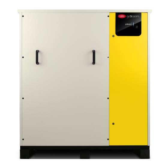
1. INTRODUCTION AND INSTALLATION gaSteam (UG*) Range of isothermal gas-fi red humidifi ers for steam production control and distribution, fi tted with touch screen graphic display. Models available (identifi ed by the part number shown on the packaging label and on the rating plate): UG045, UG090, UG150, UG180, UG300, UG450 with steam production capacity up to 450 kg/h (992 lb/h). -
Page 8: Opening The Appliance
Positioning • For installation choose the most suitable position for steam distribution, that is, the position that minimises the length of the steam pipe. The unit has been designed to be fl oor standing, on a base that supports its weight in normal operating condi- tions (see the table of “Dimensions and weights”). -
Page 9: Material Supplied
Indoor model Outdoor model Unscrew the screw using a fl at-head screwdriver (B) and Procedure: open the door to access the electrical panel (Q). 1. Turn the disconnect switch (D) OFF to electrically dis- connect the unit; 2. Turn the key in the lock (L) and open the door to ac- Fig. -
Page 10: Rating Plate
Serial No. Date Rev. Part No. MADE IN ... CAREL INDUSTRIES Via dell'Industria, 11, 35020 Brugine (Padova) Italy Fig. 1.g Notice : tampering, removal or absence of the rating plate or anything else that does not allow certain identifi cation of the product will make any installation or maintenance operations diffi... -
Page 11: Dimensions By Model - Mm (In)
Dimensions by model - mm (in) 1.9.1 Indoor models 1443 (56.8) UG45-90-150 1123 (44.2) 741 (29.2) indoor 591 (23.3) 524 (20.6) Flue gas outlet Steam outlet 107 (4.2) 57 (2.2) 109 (4.3) 58 (2.3) Drain Water column supply Drain Inspection tempering opening Water... - Page 12 1443 (56.8) UG180-300 1051 (41.4) indoor 870 (34.3) 821 (32.3) 719 (28.3) 340 (13.4) Steam outlet (Mod. 300) Flue gas outlet (Mod. 300) Steam outlet (Mod. 180) 107(4.2) 58 (2.3) 103 (4.1) 57(2.2) Water supply Drain column Inspection Drain opening tempering Water drain...
- Page 13 1.9.2 Outdoor models 1560 (61.4) UG45-90-150 outdoor 290 (11.4) 107 (4.2) 57 (2.2) 109 (4.3) 58 (2.3) Water Flue gas supply Drain outlet column Drain tempering Water drain Gas supply 925 (36.4) Tank water drain 222 (8.7) Steam outlet Air intake Fig.
- Page 14 1560 (61.4) UG180-300 outdoor 664 (26.1) 107 (4.2) 287 (11.3) 103 (4.1) 57 (2.2) 58 (2.3) Drain Water column supply Flue gas outlet Drain tempering Water drain supply Tank 632 (24.9) 327 (12.9) water 402 (15.8) drain 222 (8.7) Steam outlet Air intake Fig.
- Page 15 1620 (63.8) UG450 outdoor 729 (28.7) 105 (4.1) 528 (20.8) 698 (27.5) 332 (13.1) 587 (23.1) 376 (14.8) 300 (11.8) 325 (12.8) 327 (12.9) 148 (5.8) 58 (2.3) 145 (5.7) Water supply Drain column Steam outlet Drain tempering Flue gas outlet Water supply...
-
Page 16: Piping Connections
2. CONNECTIONS Caution: before making the connections, disconnect the power supply by turning the main switch to OFF. Piping connections gaSteam requires a connection to the gas and water supply and water drain pipes. The feedwater supply can be connected using a hose with a minimum inside diameter (recommended) of 6 mm. -
Page 17: Drain Water Characteristics
If, on the other hand, the humidifi er is supplied with water from a Carel reverse osmosis system connected to the potable water supply network, the double check valve must be installed on the inlet to the reverse osmosis system. -
Page 18: Air Intake And Fl Ue Connections
Caution: completely demineralised water is aggressive. For connection to a feedwater system with completely demineral- ised water, only use components made from chemically-resistant plastic (e.g. polypropylene) or stainless steel. Air intake and fl ue connections The gaSteam humidifi er is an approved type C appliance (sealed appliance). Regarding the installation type, the following con- fi... - Page 19 Flue gas accessories (to be purchased separately): Fig. 2.e Ref. Description Ref. Description Stainless steel fl ue grille, Ø 80 mm EXHZ080000 “T” connector Ø 80 mm EXHD080000 Ø 80 mm extension, L = 1000 mm EXHP080100 EXHG000000 Ø 80 mm extension, L = 500 mm EXHP080500 Condensate drain trap with drain pipe EXHDS00000...
-
Page 20: Pressure Switch
Pressure switch The pressure switch (P/N UGKPRES180, not supplied) is used to verify that there is no return of fl ue gases in the event of instal- lation with a common fl ue/chimney. Checks Verity that the water connections are correct, as follows: •... -
Page 21: Steam Distribution
3. STEAM DISTRIBUTION To achieve optimal humidifi er effi ciency, the steam produced must be introduced into the room uniformly, in order to prevent the formation of droplets and condensation. This is achieved using linear steam distributors. The right steam distributor must be chosen according to the place where the steam is to be introduced. - Page 22 Mounting instructions (see the fi gure): • drill a series of holes in the wall of the pipe, using the drilling jig of the distributor (found in the packaging of the distributor); • insert the distributor with the steam outlet holes facing upwards; •...
-
Page 23: Steam Blower For Room Installation
High-effi ciency linear distributors for air ducts or AHUs High-effi ciency linear distributors (sold separately), can be used in all cases where the formation of condensate needs to be reduced inside the distributor itself. All the information provided in the paragraph on linear distributors still applies; the dimen- sions and diameters are shown below. -
Page 24: Steam Hose
Steam hose Warnings: • use CAREL hoses (max length = 4m, see “Steam hose models”); • avoid the formation of pockets or traps (these cause condensate accumulation) • avoid choking the hose with sharp bends or twists. • use metal clamps to secure the ends of the hose to the connections on the humidifi er and the steam distributor so that they do not come loose due to the high temperatures. -
Page 25: Outlet Pressure Limits
Outlet pressure limits The back-pressure at the boiler outlet, either positive or negative, depends both on the relative pressure in the duct/AHU and the pressure drop in the steam hose, due to bends or adapters, and the steam distributor. The steam hoses have a pressure drop of around 150 Pa/m (0.021 psi) (in compliance with the maximum recommended fl... -
Page 26: Electrical Connections
DIN rail, connect- ed directly to the main transform- er (primary 115 V, secondary 230 to the transformer (connection by Carel) Fig. 4.c gaSteam +0300090EN rel. 1.4 - 25.02.2021 Electrical connections... -
Page 27: Power Supply
Notice : to avoid unwanted interference, the power cables should be kept separate from the probe signal cables. Caution: connect the yellow-green wire to the earth terminal (GND). Power supply The humidifi er power line must be fi tted by the installer with a disconnect switch and protection fuses. The table shows the recommended size of the power cable and fuse ratings. - Page 28 c.pHC control board 1 2 3 J17C J17L Ethernet Unit Alarm RS485 Serial status relay Control signal relay Fig. 4.e Terminal Function Electrical specifi cations M1.1 GND (G0) M1.2 Controller power supply 24Vac +10%/-15% 50/60Hz M2.1 Main room probe input 0-1V, 0-10V, 2-10V, 0-20mA, 4-20mA, NTC 10 kΩ...
-
Page 29: Operation And Control
Operation and control Before describing the electrical connections to the terminals in detail, below is an introduction to the humidifi er control principles. 4.6.1 Operating principle of a gas-fi red humidifi er In a gas-fi red humidifi er, the production of steam is obtained inside a boiler containing water that is heated to and then held at boiling temperature. -
Page 30: Steam Production Control Signals
To verify that the relative humidity measured by the probe is within certain predefi ned values, two alarm thresholds can be set in autonomous control: • high relative humidity; • low relative humidity. When these thresholds are exceeded, an alarm is activated and the corresponding relay contact is closed. 4.6.5 Autonomous control with relative humidity probe and outlet limit probe In this case too, the controller modulates steam production based on the % rH measured by the main relative humidity probe, while limiting production if the humidity measured by a second limit probe, located in the air duct downstream of the steam... - Page 31 HUMIDISTAT and REMOTE CONTACT (ON/OFF operation) • connect terminals 1U and 2U (production request) to a humidistat; • connect inputs 7U and 8U (enable) to a remote contact (e.g.: switch, timer,...); • to enable ON/OFF operation, set: Index Parameter Description Ea01 Control type External ON/OFF signal...
-
Page 32: Control With Humidity Probes
EXTERNAL PROPORTIONAL CONTROLLER and REMOTE CONTACT (modulating operation) with LIMIT PROBE • short-circuit terminals 7U and 8U (jumper) to enable production; alternatively connect terminals 7U – 8U to a remote contact (e.g.: switch, timer,...); • connect terminals 1U and 2U (production request) to an external controller; •... - Page 33 CONTROL WITH ONE HUMIDITY PROBE • short-circuit terminals 7U and 8U (jumper) to enable production; alternatively connect terminals 7U – 8U to a remote contact (e.g.: switch, timer,...); • connect the main active room probe to terminals 1U, 2U (GND) and 3U (+12Vdc); •...
-
Page 34: Control With Temperature Probes
Index Parameter Description Ea01 Control type Modulation with two humidity probes Ea02 Control with two probes Set the weight of the two probes (0-100%) Ea05 Modulating control Set: humidity set point (0-100 %rH) diff erential (2-20 %rh) Minimum production (25%-100%) - Maximum production (25%-100%) Ec01 Type of main probe Select from: 0-1V, 0-10V, 2-10V, 0-20mA, 4-20mA... - Page 35 1U 2U 3U 4U 5U 6U 7U 8U 9U 10U 11U 12U 13U 14U 300090_25_R01 OUT H/T + (G) Fig. 4.s CONTROL WITH ONE TEMPERATURE PROBE AND LIMIT PROBE • short-circuit terminals 7U and 8U (jumper) to enable production; alternatively connect terminals 7U – 8U to a remote contact (e.g.: switch, timer,...);...
- Page 36 1U 2U 3U 5U 6U 7U 8U 9U 10U 11U 12U 13U 14U The following probes can be connected: 300090_024_R01 probes for rooms DPWC111000 OUT H/T for air ducts DPDC110000, + (G) DPDC210000 for industrial applications DPPC210000 Tab. 4.q OUT H/T Notice : third-party active probes can also be + (G)
-
Page 37: Alarm Contact
Alarm contact The humidifi er controller is fi tted with a relay contact for remote signalling of one or more faults or alarms. The alarm contact (250 Vac; max. rating: 2 A resistive - 2 A inductive) is connected using terminals 7O, 8O and 9O. 1O 2O 3O 4O 5O 6O 7O 8O CO - Common NC - Normally closed... -
Page 38: Preparing For Operation
5. PREPARING FOR OPERATION Preliminary checks Before starting the humidifi er, check that: • the water and electrical connections have been completed and the steam distribution system confi gured according to the instructions contained in this manual; • the humidifi er water shut-off valve is open; •... - Page 39 5.2.3 Type of calibration Two diff erent types of burner calibration are available: A. Guided; B. Manual. The guided procedure automatically provides the user, step by step, with all the information necessary to complete the calibra- tion process. For the manual procedure, follow the instructions below. 5.2.4 Burner calibration at maximum output Force the burner to operate at maximum output by setting the fan to the maximum speed and analysing the fl...
- Page 40 5.2.5 Burner calibration at minimum output Force the burner to operate at minimum output, by setting the fan to the minimum speed. Procedure for both models: Using a T40 Torx screwdriver: • remove the cap to access the adjustment screw; UG45/90/180 UG150/300/450 Fig.
-
Page 41: StartUp And User Interface
6. STARTUP AND USER INTERFACE Start-up After having connected power using the main disconnect switch (ON), switch the appliance on by moving the switch on the front panel to “ON”. The activation sequence will start, which includes an initial phase, an autotest phase and fi nally actual operation. Each step in the activa- tion sequence is identifi... -
Page 42: Graphic Terminal
Shutdown • To avoid stagnation, drain the water from the boiler using the manual procedure. • move the switch to 0, “OFF”. Graphic terminal The 4.3” touch graphic terminal has a graphic interface with coloured and animated icons. The contents of the display can be scrolled up and down simply and intuitively. -
Page 43: Scheduler Settings
6.5.2 Scheduler settings Activate and set the time bands for humidifi er activation. After enabling the scheduler, six on/off time bands can be set for each day. Use the copy button to copy the set time bands from one day to the next. Fig. -
Page 44: Set Point Setting
6.5.5 Set point setting Set the set point, proportional band and maximum production Fig. 6.g 6.5.6 System information Menu providing humidifi er status, software and hardware information. Fig. 6.h Unit status may be as described below: Unit status Description Standby unit in standby and ready to operate Production the unit is producing steam... -
Page 45: Complete Programming Tree
6.5.7 Descriptive icon of humidifi er status Graphic display of unit status via animated icons. The status may be: Fill (fi ll valve active) Drain (drain pump active) Steam production Minimum water level in the boiler (yellow and red LED on; Water level above the maximum limit in the boiler (green LED on). Complete programming tree Below is the complete tree of the settings menu. - Page 46 Menu E. Settings(password) Menu Index Description Level a. Control Control type Ea01 Set the type of control Installer Weights Ea02 Set the weight of the two probes Installer Control proportional Ea03 Set the hysteresis, minimum production and max production Installer to external signal External ON/OFF Ea04...
- Page 47 Menu Index Description Level Number of evap. cycles Ec11 Set the number of evaporation cycles between two drain cycles Installer before draining Number of evap. cycles Ec11a Set the number of evaporation cycles between two drain cycles Installer before draining (for the secondary unit, if present) Variation in...
- Page 48 Menu Index Description Level g. Initialisation Wizard Eg01 Start the wizard for initial unit confi guration Service, Set whether to display the wizard when next restarting Installer Language Eg02 Set the language Service, Installer Unit of measure Eg03 Set unit of measure (International or Imperial). Select the language Installer and language when starting when starting...
-
Page 49: User Menu And Unit Configuration
7. USER MENU AND UNIT CONFIGURATION The following paragraphs describe the gaSteam programming menus. The screen index at the top right corresponds to the sequence in each menu in order to reach the specifi c page. Main menu 7.1.1 Clock menu The Clock menu is used to set the time, date and time zone. -
Page 50: Scheduler Menu
From the system menu, enter the “alarm thresholds” menu: Parameter Description Alarm thresh- Set alarm thresholds olds Low humidity/temperature alarm threshold High humidity/temperature alarm threshold Limit humidity/temperature alarm threshold Default: low humidity/temperature 0% rH / 0°C(32°F); high humidity/temperature 100% rH / 100 °C(°F); high limit humidity/temperature 100% rH / 100 °C(°F);... -
Page 51: Menu E. Settings - A. Control
Menu E. Settings - a. Control Fig. 7.h Login with password is required to access the settings menus: • service 0044; • installer: 0077. From the system menu, enter the “Settings” menu and enter the password. Then click the “Confi guration” icon: Fig. - Page 52 For “humidity (two probes)“ or “temperature (two probes)” control, only a group of main probes can be defi ned. Wired probes can be connected to the main probe input (1U) and the limit probe input (5U), which will be used as a second probe, with the average calculated.
- Page 53 7.2.6 Integral function in probe control If using a probe that is connected directly to the humidifi er (control: humidity probe), the integral (I) control function can be selected. This means the humidity level over time can be considered, bringing the value to the set point even when the propor- tional action (P) alone is null.
-
Page 54: Menu E. Settings - B. Functions
The conductivity is read periodically, and the maintenance alarm times is thus updated as a consequence. Thus, for example, if a water hardness of 15°f is set, the “maintenance warning” time will correspond to 1500 actual boiler operating hours; if the “maintenance pre-alert”... - Page 55 Preheat with autonomous modulating control with probes The preheating function, if active, overlaps the control diagram and modulates the power delivered to the heaters in relation to the water temperature and the preheating set point. %production Pmax Steam_Pr offset Pmin Preh Steam_pr Steam production...
- Page 56 7.3.3 Total drain due to inactivity (Installer menu) For reasons of hygiene, it is recommended to empty the boiler so as to prevent water from stagnating inside when there is no humidifi cation request for an extended period. The user can set the automatic total drain due to inactivity time in hours: Index Parameter Description...
-
Page 57: Frost Protection
7.3.6 Blower unit confi guration (Installer menu) To best manage the blower units in applications where steam is delivered directly into the room, the blower on and off times can be set. Delaying activation of the blower unit allows the system to reach the operating temperature before the fan is activated. Delaying deactivation of the blower unit guarantees that parts in contact with the steam will be completely dried, and that when next starting, there is no condensate in the blower (no droplets delivered into the room). -
Page 58: Menu E. Settings - C. Confi Guration
In addition to these functions, on outdoor models there is also a normally-open valve connected to a temperature probe (in- dependent), which completely drains the boiler if it measures a temperature of 3°C (37.4°F) (default value, can be set manually). In addition, special heaters can also be installed inside the unit, which work independently (kit to be purchased separately: P/N UGKHEAT115 for 115 Vac models, UGKHEAT230 for 230 Vac models). - Page 59 7.4.3 Wireless probes (Installer menu) Confi guration of the wireless probes involves defi ning the weight of each probe; for further details on the averages see para- graph 7.2.2 “Weighted average of the probes”. Screen Ec03 can be used to deactivate, activate as main probe or limit probe each of the four possible wireless probes.
- Page 60 Notice : if the drain to dilute time is very short, there may be the RISK OF FOAM/CORROSION due to increased internal conductivity. Low values should be set for the “variation in drain time” parameter only after having carefully evaluated the water quality and the consequences.
- Page 61 7.4.8 Enable and set high conductivity alarm (Installer menu) The controller allows conductivity thresholds to be set for the activation of alarms when the limits are exceeded. Excessive conductivity and consequently high concentration of salts in the feedwater can be signalled. These alarm thresholds are pro- grammable using the following parameters: Index Parameter...
- Page 62 Display Value and notes Default Unit of measure Max speed Fan speed at rated prod. UG045 = 4700 UG090 = 5050 Set the fan speed set point at rated production UG150 = 6750 UG180 = 5300 UG300 = 6750 UG450 = 6750 Tab.
- Page 63 Menu E. Settings - d. Main/Secondary 7.5.1 Main/Secondary system network settings (Installer menu) To increase total production capacity when one single unit is not suffi cient, the Main/Secondary function can be used to con- nect up to 20 units together in just one system. To set and enable the individual units in the system, go to the “Network” menu, specifi...
-
Page 64: Menu E. Settings - E. Backup
Menu E. Settings - e. Backup 7.6.1 Enable backup unit (Installer menu) In some critical applications where relative humidity control is very important, it may be essential have a backup unit available in the event of malfunctions on the main unit. To enable the backup unit, go to screen Ee01: Index Parameter Description... - Page 65 7.8.6 Software update from USB pen drive The update package can be downloaded from ksa.carel.com. The unit’s software can be updated using a USB pen drive plugged directly into the c.pHC controller. In the pen drive’s root directory, create an UPGRADE directory and copy the software update fi...
- Page 66 Address is the device’s supervision address on the BMS port. Enabling or disabling the parameters “On/Off from SV” and “Control from SV” activates or deactivates the response to the corresponding signals from the supervisor. For other supervisor protocols, select Carel protocol and use the Carel external gateway (supernode for humidifi cation). 7.9.2 BMS port (Installer menu) Screen Eh02 is used to set supervisor communication on the BMS port.
- Page 67 fi rewall guarantees remote access only via a secure connection (Carel tERA cloud or encrypted VPN connection). 7.9.5 Supervisor settings for ModBus or BACnet on TCP/IP (Ethernet port) (Installer menu) Both Modbus and BACnet are available on the Ethernet port;...
-
Page 68: Menu E. Settings - I. Logout
7.9.7 Settings for monitoring service Monitoring service refers to a system that does not have the ability to manage/act on the unit, but rather simply monitor its operation. The parameters relating to the management of an external monitoring service are shown on screen Eh09. However, a unit pause signal from an external source can be managed and disabled by activating the corresponding bypass. -
Page 69: Description Of The System
8. MAIN/SECONDARY SYSTEM Description of the system To obtain steam production higher than that provided by one single unit, several humidifi ers can be connected together in a Main/Secondary system. A maximum of 19 Secondary units can be connected to each Main, meaning a total of 20 humidifi ers. The Main and Secondary units are connected using a local Ethernet network, and in the case of just two units (one Main and Secondary) involves a direct connection between the two controllers via Ethernet RJ45 Category 5 cable. -
Page 70: Switch For Connection
Switch for connection The Main/Secondary connection of more than two units requires the use of an industrial grade switch. The switch (P/N: can connect a maximum of eight units (8 Ethernet ports). If necessary, use several switches with a cascaded arrangement. Technical specifi... -
Page 71: System Configuration
Slave Master Slave IP: 192.168.1.2 IP: 192.168.1.1 IP: 192.168.1.3 main probe main probe or external signal or external signal Fig. 8.e System confi guration Systems set up in this way will be able to cover the humidifi cation requirement. In this specifi c case, the Main unit will always be the unit with the lowest IP address of those connected to the signal/probes. - Page 72 8.4.1 Maximum production In the same way as for the individual unit confi guration, for the Main/Secondary system the maximum capacity can also be set. Procedure: Enter menu Ed07 (E. Settings - d. Network), press PRG and scroll with UP/DOWN until reaching menu Ed03. The “Capacity” pa- rameter identifi...
-
Page 73: Software Backup
The units in the Main/Secondary system can also be selected one by one, displaying maximum production, unit status, operat- ing hours, current production request and any alarms. To enter this display, from screen Ed08, select the desired unit and press ENTER, thus accessing screen Ed09. -
Page 74: Built-In Web Server
Caution: the controller is not accessible directly on the internet as a fi rewall guarantees remote access only via a secure connection (Carel tERA cloud or encrypted VPN connection). gaSteam +0300090EN rel. 1.4 - 25.02.2021 Web server... -
Page 75: Web Server Functions
Info Unit info: information on the unit model and software version. Select language and unit of measure. Resources: useful links (Carel website, gaSteam manuals and pages on Carel website). Guide & FAQ: general information on using the web server. Notice : to avoid incorrect settings, some of the main unit operating parameters can only be modifi... -
Page 76: Unit Hardware Backup
10. UNIT HARDWARE BACKUP For applications that require continuous humidity control, a second backup unit may be required, which is automatically activat- ed in the event of a malfunction on the fi rst. The gaSteam controller features a dedicated digital input and output for the backup connection, so as to guarantee, via the normally-open contact, activation of the second unit. -
Page 77: Supervisor Network
11. SUPERVISOR NETWORK 11.1 Protocols and confi guration The humidifi er can be connected to a supervisor via serial (BMS) or Ethernet network. The Carel, ModBus and BACnet protocols are supported as standard by the units. Ethernet Fig. 11.a Port Terminal on c.pHC controller... - Page 78 Type Add. Variable name Description Default Access Ana- AlrmThrshTempLo Set main probe low temperature alarm threshold AlrmThr- DegreesCelsius ReadWrite logue shTem- Ana- AlrmThrshTempHi Set main probe high temperature alarm threshold 60.0 AlrmThr- DegreesCelsius ReadWrite logue shTempLo Ana- AlrmThrshTempHiLim Set limit probe low temperature alarm threshold 60.0 DegreesCelsius ReadWrite logue...
- Page 79 Type Add. Variable name Description Default Access Ana- ManMode_Fan2_PWM Set fan 2 speed in manual mode Fan_2_cfg. Fan_2_ Revolutions ReadWrite logue MinSpeed cfg.Max- PerMinute Speed Ana- ManMode_Fan3_PWM Set fan 3 speed in manual mode Fan_1_cfg. Fan_1_ Revolutions ReadWrite logue MinSpeed cfg.Max- PerMinute Speed...
- Page 80 Type Add. Variable name Description Default Access Boolean 76 Alrm_NetUnit_10. Alarm ALN10: Problems on network unit 10 ReadWrite Active Boolean 77 Alrm_NetUnit_11. Alarm ALN11: Problems on network unit 11 ReadWrite Active Boolean 78 Alrm_NetUnit_12. Alarm ALN12: Problems on network unit 12 ReadWrite Active Boolean 79...
- Page 81 Type Add. Variable name Description Default Access Boolean 140 Alrm_LowProd_S. Alarm ALB03: Secondary low production ReadWrite Active Boolean 141 Alrm_LevSen_S.Active Alarm ALC05: Secondary level sensor broken ReadWrite Boolean 142 Alrm_Autotest_S.Active Alarm ALC06: Secondary autotest failed ReadWrite Boolean 143 Alrm_CylFull_S.Active Alarm ALW12: Secondary boiler full alarm ReadWrite Boolean 144 Alrm_HighConduct-...
- Page 82 Type Add. Variable name Description Default Access Integer FillTScale Set additional fi lling time modifi cation after reaching Percent ReadWrite green LED level if micro-fi lling mode not active Integer DilDrainTScale Set drain time modifi cation Percent ReadWrite Integer Scheduler.SchedDay- Scheduler - Day to confi...
- Page 83 Type Add. Variable name Description Default Access Integer NetStatus[7] Status of network unit 7 * ReadWrite Integer NetStatus[8] Status of network unit 8 * ReadWrite Integer NetStatus[9] Status of network unit 9 * ReadWrite Integer NetStatus[10] Status of network unit 10 * ReadWrite Integer NetStatus[11]...
- Page 84 Type Add. Variable name Description Default Access Integer WorkHrCntDwn Time remaining until next maintenance (demineral- Hours ReadWrite ised water) Integer WorkHrCntDwn_120 Time remaining until next maintenance (mains water) Hours ReadWrite Integer CylResDate.Year Boiler production hours reset date - Year Years ReadWrite Integer CylResDate.Month...
- Page 85 Type Add. Occ. Variable name Description Default Access Coil DilDrainCfg.DailySched[1]. Drain to dilute - Daily scheduler (Mon- TRUE ReadWrite Enable day) - enable Coil DilDrainCfg.DailySched[2]. Drain to dilute - Daily scheduler (Tues- TRUE ReadWrite Enable day) - enable Coil DilDrainCfg.DailySched[3]. Drain to dilute - Daily scheduler TRUE ReadWrite...
- Page 86 Type Add. Occ. Variable name Description Default Access DiscreteInput Alrm_NetUnit_1.Active Alarm ALN01: Problems on network ReadWrite unit 1 DiscreteInput Alrm_NetUnit_2.Active Alarm ALN02: Problems on network ReadWrite unit 2 DiscreteInput Alrm_NetUnit_3.Active Alarm ALN03: Problems on network ReadWrite unit 3 DiscreteInput Alrm_NetUnit_4.Active Alarm ALN04: Problems on network ReadWrite unit 4...
- Page 87 Type Add. Occ. Variable name Description Default Access DiscreteInput Al_AntiFreeze_1.Active Alarm ALA13: Frost protection check ReadWrite components DiscreteInput Al_Secondary_450_Of- Alarm ALA14: Secondary 450 online ReadWrite fLine.Active DiscreteInput Al_Main_450_Off Line. Alarm ALA15: Main 450 offl ine ReadWrite Active DiscreteInput Al_AntiFreeze_2_Second- Alarm ALA17: Secondary frost protection ReadWrite ary.Active DiscreteInput...
- Page 88 Type Add. Occ. Variable name Description Default Access HoldingReg- AlrmThrshTempHi Set main probe high temperature alarm 60.0 AlrmThr- 0.1[°C]/ ReadWrite ister threshold shTempLo [°F] HoldingReg- AlrmThrshTempHiLim Set limit probe low temperature alarm 60.0 100.0 0.1[°C]/ ReadWrite ister threshold [°F] HoldingReg- ThrshAlrmDT Delay for each humidity/temperature ReadWrite...
- Page 89 Type Add. Occ. Variable name Description Default Access HoldingReg- SchedDayCfg[3].SetP Scheduler - Set point for ON+SET mode 100.0 ReadWrite ister (2) (2) (Thursday) HoldingReg- SchedDayCfg[4].StartHr Scheduler - Time band start time (Friday) ReadWrite ister HoldingReg- SchedDayCfg[4].StartMin Scheduler - Time band end time (Friday) ReadWrite ister HoldingReg-...
- Page 90 Type Add. Occ. Variable name Description Default Access HoldingReg- DilDrainCfg.DailySched[3]. Drain to dilute - Daily scheduler ReadWrite ister Start_h (Wednesday) - hours HoldingReg- DilDrainCfg.DailySched[3]. Drain to dilute - Daily scheduler [min] ReadWrite ister Start_min (Wednesday) - minutes HoldingReg- DilDrainCfg.DailySched[4]. Drain to dilute - Daily scheduler (Thurs- ReadWrite ister Start_h...
- Page 91 Type Add. Occ. Variable name Description Default Access InputRegister WirelessPrbVal_4.Hum Wireless probe 4 - Humidity value in %rH ReadWrite (SA and SI probes only) InputRegister WirelessPrbVal_4.Temp Wireless probe 4 - Temperature value ReadWrite in °C InputRegister WirelessPrbInfo_4.BattLev Wireless probe 4 - Battery level from 0 ReadWrite to 3600 mV (below 2800 mV the battery level is low)
- Page 92 Type Add. Occ. Variable name Description Default Access InputRegister ID_Lang Current user interface language (0 = Eng- ReadWrite lish; 1 = Italian; 2 = French; 3 = German; 4 = Spanish) InputRegister WorkHrCntDwn_Sec- Time remaining until next maintenance ReadWrite ondary (demineralised water), Secondary InputRegister WorkHrCntDwn_120_...
- Page 93 Type Address Variable name Description Default Min Access AnalogValue 16 MainPrbCfg.Ma_Hum Main probe confi guration - 100.0 Per- ReadWrite Maximum for humidity control centRel- ativeHu- midity AnalogValue 17 MainPrbCfg.Mi_Temp Main probe confi guration - -20.0 Degree- ReadWrite Minimum for temperature control sCelsius AnalogValue 18 MainPrbCfg.Ma_Temp...
- Page 94 Type Address Variable name Description Default Min Access AnalogValue 63 ManMode_Fan2_PWM Set fan 2 speed Fan_2_cfg. Fan_2_ Revo- ReadWrite in manual mode MinSpeed cfg.Max- lution- Speed sPerMin- AnalogValue 64 ManMode_Fan3_PWM Set fan 3 speed Fan_1_cfg. Fan_1_ Revo- ReadWrite in manual mode MinSpeed cfg.Max- lution-...
- Page 95 Type Address Variable name Description Default Min Access BinaryValue Alrm_NetUnit_7.Active Alarm ALN07: Problems on network unit 7 ReadWrite BinaryValue Alrm_NetUnit_8.Active Alarm ALN08: Problems on network unit 8 ReadWrite BinaryValue Alrm_NetUnit_9.Active Alarm ALN09: Problems on network unit 9 ReadWrite BinaryValue Alrm_NetUnit_10.Active Alarm ALN10: Problems on network unit 10 ReadWrite BinaryValue...
- Page 96 Type Address Variable name Description Default Min Access BinaryValue Warn_LevSen_S.Active Warning ALW10: Secondary level sensor ReadWrite BinaryValue Warn_LowProd_S.Active Warning ALW11: Secondary low production ReadWrite BinaryValue Al_AntiFreeze_2.Active Alarm ALA16: Frost protection force preheating ReadWrite BinaryValue EnHiConductAlrm Enable high conductivity alarm TRUE ReadWrite BinaryValue ManDrain...
- Page 97 Type Address Variable name Description Default Min Access Positive DilDrainTScale Set drain time modifi cation Percent ReadWrite IntegerValue Positive Scheduler.SchedDayToSet Scheduler - Day to confi gure ReadWrite IntegerValue (a value > 0 enables editing mode) Positive SchedDayCfg[0].StartHr Scheduler - Time band start time (Monday) ReadWrite IntegerValue Positive...
- Page 98 Type Address Variable name Description Default Min Access Positive WorkHr Total unit operating hours Hours ReadWrite IntegerValue Positive CylWorkHr Boiler production hours Hours ReadWrite IntegerValue Positive NetStatus[1] Status of network unit 1 * ReadWrite IntegerValue Positive NetStatus[2] Status of network unit 2 * ReadWrite IntegerValue Positive...
- Page 99 Type Address Variable name Description Default Min Access Positive DilDrainCfg.DailySched[4]. Drain to dilute - Hours ReadWrite IntegerValue Start_h Daily scheduler (Thursday) - hours Positive DilDrainCfg.DailySched[4]. Drain to dilute - Minutes ReadWrite IntegerValue Start_min Daily scheduler (Thursday) - minutes Positive DilDrainCfg.DailySched[5]. Drain to dilute - Hours ReadWrite...
-
Page 100: Wireless Probes
12. WIRELESS PROBES 12.1 Installation and electrical connections For installations where standard wired probes can not be used, (for example, modifi cations to existing systems), wireless probes can be used. These are connected via a device called an access point (P/N: WS01AB2M20), for up to 4 wireless probes. The wire- less probes available are for room installation (WS01G01M00) or industrial applications (WS01F01M00), both of which measure humidity and temperature. -
Page 101: Wireless Probe Installation
12.2 Wireless probe installation The main steps for installing the wireless devices are: • power up the access point (12/24 Vac/dc ±10%m, 100 mA) and complete the initialisation procedure, creating the network and selecting the channel; • after having opened the domain on the access point, complete the binding procedure so as to uniquely identify each probe. The address to be used by the access point is set using the dipswitches on the device, and is the following: Rx- Rx+ GND L1L2 L3... -
Page 102: Alarm Table
13. ALARM TABLE Any active alarms will be shown on the corresponding screen with direct access from the display. The Alarm icon starts fl ashing; pressing the Alarm button once displays the type of alarm. In the event of potentially dangerous alarms, the humidifi er auto- matically stops steam production. - Page 103 Alarm Cause Possible solution Reset Action ALA02 Limit probe Limit probe or second probe not Check probe connection and the type of Manual Stop pro- broken or connected or damaged control selected duction disconnected ALA03 Preheating NTC water temperature probe not Check preheating operation and the set- Automatic Stop pro-...
- Page 104 Alarm Cause Possible solution Reset Action ALA10..12 Burner 1-3 no • ignition failure on burner 1-3. No • check the gas pressure and that the gas Stop with Stop pro- fl ame alarm fl ame with production request. shut-off valve is open; manual reset duction •...
- Page 105 Alarm Cause Possible solution Reset Action ALW12 Boiler Boiler full of water to the • Check the fi ll valve for leaks; alarm on Sec- high level sensor on the • Check whether the high level sensor ondary cover, without request is dirty;...
- Page 106 Alarm Cause Possible solution Reset Action ALW09 Autotest Manual forcing stop self-test Signal only cancelled warning ALW10 Level sensor Level sensor warning on Second- • Switch the unit off and clean the boiler, Signal only warning on ary unit. the level sensor and the fi ll solenoid Secondary The level sensor may not be work- valve...
-
Page 107: Spare Parts And Maintenance
14. SPARE PARTS AND MAINTENANCE Before all operations: • disconnect the appliance from the mains power supply; • close the water supply and gas shut-off valves; • drain the water circuit using the manual electric pump function or the drain valve provided, after connecting a pipe to drain the water outside of the unit and avoid fl... -
Page 108: Cleaning The Burner
Fig. 14.c Fig. 14.d To remove the heat exchanger, proceed as follows: • disconnect the cables from the burner electrodes (the detection electrode must be disconnected from the burner control board, see the fi gure, pos. “A”); • remove the fan manifold by undoing the screws B (Fig. 14.c) and remove the burner combustion head (Fig. 14.d); •... -
Page 109: Checking Ionisation Current
Fig. 14.g Fig. 14.h 14.3 Checking ionisation current Ionisation current is checked by placing a microammeter set to 10 μA full scale (direct current) in series with the fl ame detection electrode. Incorrect positioning of the electrode may lead to a decrease in the ionisation current and burner shutdown due to incorrect fl... -
Page 110: Cooling Fan
14.6 Fuses Fuses 1, 2, 3 measure 10.3x38 mm and are contained inside the fuse carrier; while fuse 4 measures 6.3x20 mm; to check the fuses, test continuity using a tester. Use fuses with the ratings indicated in the table: 14.7 Cooling fan The cooling fan starts when the unit is switched on, and is used to keep the operating temperature of the electrical panel and the electronics within the design limits. -
Page 111: Electrical Panel
15. WIRING DIAGRAMS 15.1 Electrical panel 300090_153_R01 J17C J17L J6L J6C Fig. 15.a gaSteam +0300090EN rel. 1.4 - 25.02.2021 Wiring diagrams... - Page 112 15.2 Wiring diagram for UG045 - UG090 - UG150 Fig. 15.b gaSteam +0300090EN rel. 1.4 - 25.02.2021 Wiring diagrams...
- Page 113 15.3 Wiring diagram for UG180 - UG300 Fig. 15.c gaSteam +0300090EN rel. 1.4 - 25.02.2021 Wiring diagrams...
-
Page 114: Wiring Diagram For Ug450
15.4 Wiring diagram for UG450 Fig. 15.d gaSteam +0300090EN rel. 1.4 - 25.02.2021 Wiring diagrams... - Page 115 Fig. 15.e Wiring diagram key Ref. Description Ref. Description Base Selectable fuse carrier ON/OFF switch (outdoor) cPHC Main board + expansion card Two-pole ON/OFF switch Diff erential pressure switch (180/300/450 kg/h) K.MINIMA Safety thermostat (outdoor only) 3-pin through connector TRPS2 115-230 V transformer (UG180-300) 4-pin through connector F1-F2...
- Page 116 15.5 Electrical panel PANEL BOARD G0 G PANEL BOARD BOTTOM SIDE FRONT cPHC 1U 2U 3U 4U 5U 6U 7U 8U 9U 10U 11U 12U 13U 14U L2 GND 1T 2T 3T 4T 5T 6T 7T 8T 9T 10T 11T 12T 13T 14T 1A 2A 3A 4A 1S 2S 3S 4S 5S 6S 7S 8S 9S 10S 11S 12S 13S 14S 1Z 2Z 3Z 4Z 5Z 6Z 7Z 8Z 9Z 10Z 11Z 12Z...
-
Page 117: General Features And Models
16. GENERAL FEATURES AND MODELS Models for indoor installation: INDOOR models UG045 UG090 UG150 UG180 UG300 rated supply voltage (Vac) 230V 50Hz (ver. UG***HD004) / 115V 60 Hz (ver. UG***HD1104) steam connection (Ø mm) 2x40 2x40 1x80 4x40 2x80 steam outlet pressure limits (Pa) 0-2000 (0-0.30 PSI) Feedwater connection... -
Page 118: Heating-Water Circuit Specifi Cations
16.1 Heating-water circuit specifi cations UG045 UG090 UG150 UG180 UG300 UG450 heat input rated kW (BTU/h) 33 (112763) 62.5 (213449) 105 (358275) 125 (426518) 210 (716550) 315 (1074825) minimum 7.8 (26614) 14.7 (50158) 24.7 (84280) 14.7 (50158) 24.7 (84280) 24.7 (84280) heat input rated 34.8 (118742) - Page 119 16.4 Linear distributor models and typical installations gaSteam humidifi er outlet Ø mm 2x40 4x40 2x80 3x80 (2x 1.6”) (3.1”) (4x 1.6”) (2x 3.1”) (3x 3.1”) humidifi er capacity kg/h max distributor distributor minimum width capacity kg/h part number UG045 UG090 UG150 UG180 UG300 UG450 inlet (ØA) mm (in) of duct/AHU mm (in) (lbs/h)
- Page 120 Typical installations of gaSteam series gas-fi red humidifi ers: UG045 e UG090 UG045 e UG090 Steam outlet: 2 x Ø 40 mm Steam outlet: 2 x Ø 40 mm Ø 40 mm Ø 40 mm (1312367AXX) (1312367AXX) Ø 40 mm (1312367AXX) Ø...
- Page 121 17. CONFORMITY gaSteam +0300090EN rel. 1.4 - 25.02.2021 Conformity...
- Page 122 Notes gaSteam +0300090EN rel. 1.4 - 25.02.2021 Notes...
- Page 124 CAREL INDUSTRIES - Headquarters Via dell’Industria, 11 - 35020 Brugine - Padova (Italy) Tel. (+39) 049.9716611 - Fax (+39) 049.9716600 gaSteam +0300090EN rel. 1.4 - 25.02.2021 e-mail: carel@carel.com - www.carel.com...
Need help?
Do you have a question about the gaSteam-UG and is the answer not in the manual?
Questions and answers