
Subscribe to Our Youtube Channel
Related Manuals for Carel gaSteam 45 HD003


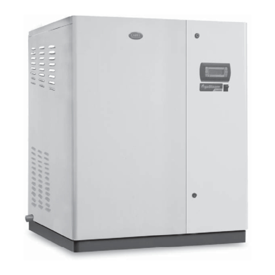
Summary of Contents for Carel gaSteam 45 HD003
- Page 1 gaSteam 45/90/180 HD003 45/90/180 HD103 hardware Manuale d’uso User manual NO POWER & SIGNAL CABLES TOGETHER READ CAREFULLY IN THE TEXT! H i g h E f f i c i e n c y S o l u t i o n s...
- Page 2 DANGER OF WATER LEAKS The liability of CAREL in relation to its products is specifi ed in the CAREL general The humidifi er automatically and constantly fi lls/drains certain quantities of contract conditions, available on the website www.carel.com and/or by...
-
Page 3: Table Of Contents
3.5 Air inlet and fl ue connections ..............10 3.6 Checks ......................... 11 3.7 Gas connections ....................12 3.8 Venting Requirements for CAREL gaSteam units........12 4. STEAM DISTRIBUTION 4.1 Steam distribution in ducts - linear distributors ........14 4.2 Positioning the linear distributors in the air ducts ........14 4.3 Installation of the steam hose .............. -
Page 4: Models And Description Of The Components
1. MODELS AND DESCRIPTION OF THE COMPONENTS 1.1 Models The code that marks the model of humidifi er is made up of 10 characters (Fig. 1.a). Example: the code UG180HD003 identifi es a gas-fi red humidifi er (UG) with: • rated steam production 180 kg/h (180);... -
Page 5: Assembly
2. ASSEMBLY 2.1 Receipt and storage 2.3 Removal and reassembly of the front cover • Check that the humidifi er is intact upon delivery and immediately notify the carrier, in writing, of any damage that may be due to careless To remove the front cover of the humidifi er, proceed as follows (Fig. -
Page 6: Water Connections
For the optimum operation of the unit, the use of demineralised It is recommended to use Carel hoses (code FWH3415000). water is recommended, and specifi cally the use of a reverse osmosis A mechanical fi lter should be installed to trap any solid impurities. -
Page 7: Air Inlet And Fl Ue Connections
The maximum lengths indicated in the following installations have been calculated using CAREL ducting. 3 openings are available for the air intake and fl ue gas outlet (6 on the UG180): •... -
Page 8: Checks
Flue accessories available from CAREL: Ref. Description Code Stainless steel fl ue gas outlet grill, Ø80 mm EXHZ080000 14-16 1000 mm extension Ø80 mm EXHP080100 500 mm extension, Ø80 mm EXHP080500 90° bend Ø80 mm EXHC080080 Stainless steel intake grill, Ø80 mm EXHX080000 Inside/Outside gasket Ø80 mm... -
Page 9: Gas Connections
IMPORTANT: FOR NORTH AMERICAN and 3.8 Venting Requirements for CAREL CANADIAN MARKET gaSteam units 3.7 Gas connections CAUTION: The humidifi er shall not be connected to a chimney fl ue serving any other appliance. The unit has 4 holes for the air intake and gas vent outlet (8 for the... - Page 10 gaSteam exhaust and intake confi gurations Outlets with flue manifold UG180 (EXHM80B120) independent outlets UG45-90 independent outlets UG180 Fig. 3.h Metric Exhaust/Intake Adapters (only for units: UG***HD103): For 80mm to 3”: EXHR08030I – Item shown below. This item is included in the UGKINST090 Gas connections kit for UG045 and UG090 Gas connections kit for UG180 “gaSteam HARDWARE”...
-
Page 11: Steam Distribution
For steam distribution into air ducts, the steam distributor must be sized according to the output of the humidifi er and the cross-section of the ducting. Figure 4.a provides the dimensions of the CAREL linear steel distributors. Table 4.a specifi es the minimum number and the model of the distributors recommended for the type of humidifi... -
Page 12: Installation Of The Steam Hose
4.3 Installation of the steam hose • The humidifi er must be connected to the distributor using a hose suitable for this purpose, such as the CAREL fl exible hose. • The use of unsuitable pipes or hoses may cause weakening and cracking and consequently steam leaks. -
Page 13: Connection Diagram, Ug45-90
5.4 Connection diagram, UG45-90 GND - GREEN HIGH - YELLOW LEVEL MIDDLE - SENSOR LOW - WHITE +15Vcc - BLUE NTC 1 FLUE GASES BLOWER 1 TACH RELAY P 13 S J11. 14 S TO CLIP J11.2 SHILDING 75 VA 230 V FENWALL 1 3 2 1... -
Page 14: Connection Diagram, Ug180
5.5 Connection diagram, UG180 BLOWER 2 TACH NTC 2 FLUE GASES TO CLIP J11.2 GND - GREEN SHILDING HIGH - YELLOW LEVEL SENSOR MIDDLE - LOW - WHITE +15Vcc - BLUE NTC 1 BLOWER 1 FLUE GASES TACH J11. TO CLIP PRESS SHILDING J11.2... -
Page 15: Adjusting The Humidifi Er To Different Types Of Gas
5.6 Adjusting the humidifi er to diff erent types of gas Important: The appliances are delivered calibrated and tested to operate on natural gas The humidifi er can be supplied with the following types of gas: • Natural gas (G20-G25 natural gas - factory default); •... - Page 16 PROPANE/ BUTANE/LPG CALIBRATION IMPORTANT: Do not start the burner (delivered with default calibration for natural gas!) supplied on propane or LPG until having turned the maximum gas fl ow control screw (B) around 2.5-3 turns clockwise. The heat value of propane in fact is around three times higher than natural gas, therefore the maximum gas fl...
-
Page 17: Maintenance
6. MAINTENANCE BEFORE ALL OPERATIONS: To remove the exchanger, proceed as follows (Figs. 6.a and 6.b): • disconnect the appliance from the mains power supply; • disconnect the cables from the burner electrodes (the detection • close the mains water and gas taps; electrode should be disconnected from the burner control board, Fig. -
Page 18: Cleaning The Burner
ionisation current and shut the burner down due to incorrect fl ame 6.2 Cleaning the burner detection. In this case, check the correct position and condition of the The burner must be checked by authorised and qualifi ed personnel electrode, its electrical connections, and the earth connection of the once or twice a year, according to use. -
Page 19: Operating Principle And Other Functions
7. OPERATING PRINCIPLE AND OTHER FUNCTIONS 7.1 Operating principle In a gas humidifi er the production of steam is obtained inside a boiler containing water that is heated to and then held at boiling temperature. The heat required to boil the water is provided by a heat exchanger, heated by a type C pre-mix modulating room-sealed gas burner (standards compliant), which takes in air for combustion and discharges the fl... -
Page 20: Technical Specifications
8. TECHNICAL SPECIFICATIONS models UG045 UG090 UG180 rated power supply voltage (Vac) 230 50 Hz (*003 version) / 230 60 Hz (*103 version) steam connection (dia. mm) 2x40 4x40 steam outlet pressure limits (Pa) 0…2000 (0…0.30 PSI) supply water connection 3/4”... -
Page 21: Weights
8.3 Dimensions Diemnsions in mm (inch): UG045-090 Fig. 8.a Dimensions mm (inch): UG180 Fig. 8.b description UG045-090 UG180 UG045-090 UG180 UG045-090 UG180 UG045-090 UG180 steam outlet 40 (1.574) 1020 (40.157) 1200 (47.244) 570 (22.441) 930 (36.614) fl ue 80 (3.150) 204 (8.031) 168 (6.614) 658 (25.905) 629 (24.764) -
Page 22: Rating Plate
REV. MADE IN ITALY MADE IN ITALY CAREL INDUSTRIES S.p.A. – 35020 Brugine (PD) Italy CAREL INDUSTRIES S.p.A. – 35020 Brugine (PD) Italy Via dell’Industria, 11 – Zona Industriale Via dell’Industria, 11 – Zona Industriale Tel. 049/9716611 Fax 049/9716600 Tel. - Page 23 Via dell’Industria, 11 - 35020 Brugine - Padova (Italy) Tel. (+39) 049.9716611 - Fax (+39) 049.9716600 e-mail: carel@carel.com - www.carel.com CAREL reserves the right to modify the features of its products without prior notice. “gaSteam HARDWARE” +030220940 -rel. 1.6 - 06.12.2013...
Need help?
Do you have a question about the gaSteam 45 HD003 and is the answer not in the manual?
Questions and answers