Table of Contents
Advertisement
Quick Links
Advertisement
Table of Contents

Related Manuals for gefran EXP-DN-BDI-VDI


Summary of Contents for gefran EXP-DN-BDI-VDI
- Page 1 EXP-DN-BDI-VDI English Instruction Manual for Communication Module...
- Page 2 Keep the manual in a safe place and available to engineering and installation personnel during the product functioning period. Gefran Drives and Motion S.r.L. has the right to modify products, data and dimensions without notice. The data can only be used for the product description and they can not be understood as legally stated properties.
-
Page 3: Table Of Contents
3.4 LED indicator ........................9 CHAPTER 4 COMMUNICATION MODULE FUNCTIONS ............11 4.1 Net Description ....................... 11 4.2 EXP-DN-BDI-VDI Object Modeling ................12 4.3 Object Class Define ....................... 14 4.4 EDS file .......................... 29 CHAPTER 5 DIAGNOSTICS FAST ....................30 LED indicator Diagnosis ...................... -
Page 4: Chapter 1 Summary
To Inverter, EXP-DN-BDI-VDI Communication Module connected with Inverter by RS485 communication port. DIP switch SW1_8 is required to be set OFF if EXP-DN-BDI-VDI Module is connected with the inverters of VDI100/BDI50 series. The VDI100/BDI50 series have built-in RS485 interface so they can connect with different extended communication module by Modbus protocol, such as DeviceNet Communication module, Profibus Communication module. -
Page 5: Structure Of The Unit
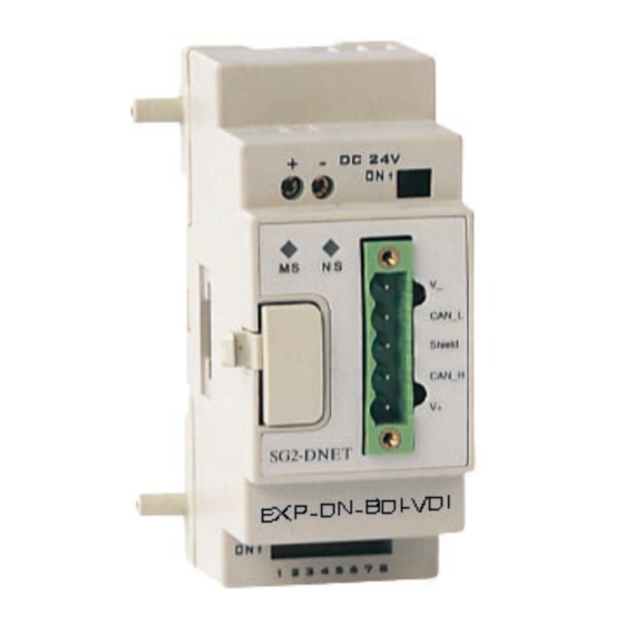
(2PIN:Selection of Network Terminating Resistor) ⑤ Module Status indicator/Network Status indicator ⑥ Press-button DIP Switch CAN_L ⑦ Shield (8PIN:Settings of Network ID and functions) CAN_H ⑧ RS485 D N ET Terminals Figure1.3: Structure of the EXP-DN-BDI-VDI Extended Module EXP-DN-BDI-VDI User Manual V01 pag. 2... -
Page 6: Description Of Communication Module
Support Support duplicate MAC Id check Support predefine master slave connection Support predefine explicit message connection Support predefine poll IO message connection Support explicit and IO message fragment EXP-DN-BDI-VDI User Manual V01 pag. 3... -
Page 7: Chapter 2 Installation
Installation EXP-DN-BDI-VDI Module can be installed vertically shown as the left side of Fig. 2.1. Fix the module to DIN rail and the rail is gripped accurately to the plastic groove. It is suggested to add clips at rail terminal to fix it. It is also suggested to install the screw M4 directly to EXP-DN-BDI-VDI module, shown as the right side of Fig.2.1. -
Page 8: Connecting Power Supply
2.2 Connecting power supply Network power supply 24VDC / 50mA and backup power supply are applied to EXP-DN-BDI-VDI module. Supply voltage range is 21.8V~26.2V. Warning: Ensure the safe electrical isolation between Extra Low Voltage and 24V power supply. ①:Fast Fuse, Breaker, Circuit Protection ②:Filter... -
Page 9: Connected With Inverter By Modbus
DeviceNet requires a terminating resistor to be installed at each end of the trunk. It is controlled by the 2-bit SW2 on the module to set in or not. Figure 2.6 terminating resistor RT=120Ω 2.6 Baud rate and max transmit length EXP-DN-BDI-VDI can support baud rate prescribed by ODVA. 125kbps 250kbps ... -
Page 10: Climatic Condition
2.7 Climatic condition Temperature : -10°C~+40°C Humidity : 95%. EXP-DN-BDI-VDI User Manual V01 pag. 7... -
Page 11: Chapter 3 Operation
Before power up, check that you have connected the power supply, the bus connection and the connection to the basic unit correctly. If the EXP-DN-BDI-VDI unit is factory setting, the net address and baud rate of the station must be set. -
Page 12: Led Indicator
There are two LED indicators built in EXP-DN-BDI-VDI communication module to quickly determine and monitor its state and bus communication. Module status LED(MS) Two colors LED (green and red) indicate EXP-DN-BDI-VDI module status, it can be used watch the device working correctly or not. MS LED information: LED status... - Page 13 Net status LED(NS) Two colors LED (green and red) indicate the status of net bus; it can be used watch EXP-DN-BDI-VDI status in the net. NS LED information: Net led(NS) Status Information Remark No exist No power up Not on line...
-
Page 14: Chapter 4 Communication Module Functions
The identifier is already specified as the connection sets up. 4.1.3 EXP-DN-BDI-VDI deviceNet function • Support self-adjust baud rate • Support duplicate nodes and check the packet •... -
Page 15: Exp-Dn-Bdi-Vdi Object Modeling
DeviceNet describes seeable data and function through the object modules. One DeviceNet equipment can be defined as a group which is based on a clear device module. DeviceNet object module describes all the EXP-DN-BDI-VDI communication function which is the basic principal of the application layer. - Page 16 Extend object (class code: 28hex、2Ahex、65hex、66hex) provides the parameters of Inverter, it can be used in automation project. Assemble object class • Assemble object (class code: 04hex) allocates and manages the internal resources associated with both I/O and Explicit Messaging Connections. EXP-DN-BDI-VDI User Manual V01 pag. 13...
-
Page 17: Object Class Define
0 = Nonexistent 1 = Device Self testing 2 = Standby 3 = Operational 4 = Recoverable Fault Major Unrecoverable Fault Serial number Serial UDINT 0x12345 number. Product Name STRUCT Product Name EXP-DN-BDI-VDI User Manual V01 pag. 14... - Page 18 4.3.2 Router Object Class code:0x02 The Message Router Object provides a messaging connection point through which a Client may address a service to any object class or instance residing in the EXP-DN-BDI-VDI devices. Class Attribute Description Byte...
- Page 19 The DeviceNet Object contains information about the EXP-DN-BDI-VDI DeviceNet interface configuration. Class Attribute Description Byte Attribute Access Name Data Default Attributes number rule type value Semantics Revision of this class Class Revision UINT Instance Attribute Description Byte Attribute Access Name...
- Page 20 Produced Conxn UINT 10******011 Identifier Field when the Connection transmits, ****** is MAC Consumed Conxn UINT 10******100 Identifier Field value that denotes message received, ****** is MAC Defines the Message Initial Comm BYTE 0x21 EXP-DN-BDI-VDI User Manual V01 pag. 17...
- Page 21 Consumed connection Path Length path attribute. Specifies the Consumed Conxn Null Application Object that Path is to receive the data consumed by this connection Object. Defines minimum time Production Inhibit UINT between data Time production. EXP-DN-BDI-VDI User Manual V01 pag. 18...
- Page 22 Size maximum this connection. value is 8. Defines timing 0(ms) Get/Set Expected Packet UINT associated with this Rate connection. Defines how to handle Watchdog USINT Inactivity/Watchdog Timeout Action timeouts: 0 Transition EXP-DN-BDI-VDI User Manual V01 pag. 19...
- Page 23 When a Connection in the Timed Out or Deferred Delete state receives a Reset request it also transitions back to the Established state. 4.3.5 Assemble Object Class code:0x04 It provides assembled controlling IO states of VDI100/BDI50 and 310 series. EXP-DN-BDI-VDI User Manual V01 pag. 20...
- Page 24 0x0E Get Attribute Single the specified attribute. Instance Service Description of service Service code Service Name Returns the contents of 0x0E Get Attribute Single the specified attribute. Modifies an attribute 0x10 Set Attribute Single EXP-DN-BDI-VDI User Manual V01 pag. 21...
- Page 25 Reference Speed high byte (SpeedRef) *3 Base inputs assemble 21 BYTE Bit7 Bit6 Bit5 Bit4 Bit3 Bit2 Bit1 Bit0 FaultRst Run2 Run1 Reference Speed low byte (SpeedRef) *3 Reference Speed high byte (SpeedRef) *3 EXP-DN-BDI-VDI User Manual V01 pag. 22...
- Page 26 Rated Frequency : 0.1Hz Get/Set BaseSpeed UINT RPM Speed 1500 *1 Parameter RateFreq operation is not supported in BDI50. Instance Service Service code Service Name Description 0x0E Get Attribute Single 0x10 Set Attribute Single EXP-DN-BDI-VDI User Manual V01 pag. 23...
- Page 27 (refer to parameter 00-02 in the inverter of VDI100/BDI50 series). *2: Parameter Jog operation is not supported in VDI100 . Instance Service Service code Service Name Description 0x0E Get Attribute Single 0x10 Set Attribute Single EXP-DN-BDI-VDI User Manual V01 pag. 24...
- Page 28 (not communication control). When NetRef is set to be site settings, the setting value of reference frequency command source is the default (refer to parameter 00-05). Instance Service Service code Service Name Description 0x0E Get_Attribute_Single 0x10 Set_Attribute_Single EXP-DN-BDI-VDI User Manual V01 pag. 25...
- Page 29 Software version of module connecting to the inverter Instance Service Description of service Service code Service Name Returns the contents of 0x0E Get Attribute Single the specified attribute. Modifies an attribute 0x10 Set Attribute Single EXP-DN-BDI-VDI User Manual V01 pag. 26...
- Page 30 Frequency (0.01Hz) RefSpeedFromNet UINT Reflected Setting Speed (RPM) Instance Service Description of service Service code Service Name 0x0E Get Attribute Single Returns the contents of the specified attribute. 0x10 Set Attribute Single Modifies an attribute EXP-DN-BDI-VDI User Manual V01 pag. 27...
- Page 31 ID and access rule. Instance Service Description of service Service code Service Name 0x0E Get Attribute Single Returns the contents of the specified attribute. 0x10 Set Attribute Single Modifies an attribute EXP-DN-BDI-VDI User Manual V01 pag. 28...
-
Page 32: Eds File
EDS offers all the necessary information of accessing and changing the device. EDS is used for the user configuration tool, easy to update and seldom required to correct the configuration software tool. You can found the .eds file : > on “Driver” download area of BDI50 or VDI100 of www.gefran.com http://www.gefran.com/en/products/522-bdi50-compact-v-f-sensorless-inverter#downloads http://www.gefran.com/en/products/523-vdi100-general-purpose-full-vector-inverter#downloads https://www.gefran.com/it/it/download/5189/attachment/all EXP-DN-BDI-VDI User Manual V01 pag. -
Page 33: Chapter 5 Diagnostics Fast
Red flash IO connection time out, waiting green flash after a few seconds. Red on ·Dup_mac_id check error Replace node address and ·Communication error and restart power up again. Normal operation mode, connected with master. EXP-DN-BDI-VDI User Manual V01 pag. 30... -
Page 34: Appendix
24Vdc / 80mA LED indicator Module status LED colors green/red Net status LED colors green/red Devicenet Connector 5 pins Isolation Function Only group2 slaver Max baud rate kbps Bus termination resistors Ω Bus address 0~63 EXP-DN-BDI-VDI User Manual V01 pag. 31... - Page 35 Fax +33 (0) 478770320 info@gefran.com.cn Fax +55 (0) 1132974012 commercial@gefran.fr comercial@gefran.com.br GEFRAN S.p.A. Via Sebina 74 GEFRAN DRIVES AND MOTION S.R.L. 25050 Provaglio d’Iseo (BS) ITALY Via Carducci 24 Manuale EXP-DN-BD I/VDI Ph. +39 030 98881 21040 Gerenzano [VA] ITALY 0.2 - 13-7-2020...
Need help?
Do you have a question about the EXP-DN-BDI-VDI and is the answer not in the manual?
Questions and answers