Table of Contents
Advertisement
Quick Links
To distinguish between the type and importance of the
information provided in these instructions for use, graphic
symbols have been used as a reference to make interpreting
the information clearer.
Indicates the contents of the various manual sections, the general
warnings, notes, and other points to which the reader's attention
should be drawn
Indicates a particularly delicate situation that could affect
the safety and correct working operation of the controller,
or a rule that must be strictly observed to avoid dangerous
situations
Indicates a condition of risk for the safety of the user, due to the
presence of dangerous voltages at the points shown
80346B_MHW_GFX-VALVOLE_0709_ENG
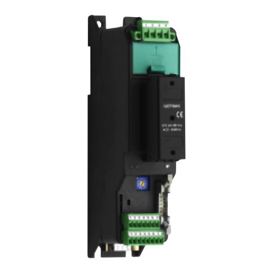
GEFLEX Valves
MODULAR POWER CONTROLLER FOR MOTORIZED VALVES
TABLE OF CONTENTS
Page
1
2
2
3
5
6
7
7
7
7
8
9
10
GRAPHIC SYMBOLS USED
OPERATING INSTRUCTIONS
AND WARNINGS
Code 80346B / Edition 0.3 - 07/09
Indicates a suggestion based on the experience of the
GEFRAN Technical Staff, which could prove
especially useful under given circumstances
Indicates a reference to Detailed Technical
Documents available on the GEFRAN web site
www.gefran.com
10
11
11
12
12
13
13
14
14
14
15
16
17
1
Advertisement
Table of Contents

Subscribe to Our Youtube Channel
Related Manuals for gefran GEFLEX


Summary of Contents for gefran GEFLEX
-
Page 1: Table Of Contents
Indicates a reference to Detailed Technical Indicates the contents of the various manual sections, the general Documents available on the GEFRAN web site warnings, notes, and other points to which the reader's attention www.gefran.com should be drawn... -
Page 2: Preliminary Instructions
Instructions for Use, as well as for the GEFLEX Multifunction Master model, the "Programming and General description Configuration manual”. -
Page 3: Installation And Connection
Direct Current. in accordance with EEC Directive EMC 2004/108/CE. Series GEFLEX Multifunction controllers are mainly designed GEFRAN S.p.A. declines all responsibility for any to operate in industrial environments, installed on the damage to persons or property caused by... -
Page 4: Overall Dimensions And Mounting Dimensions
2.1 Overall dimensions and mounting dimensions 1) Position each GEFLEX module with the longer side aligned current is less than or equal to 75% of the maximum current with the vertical axis of the electrical panel to increase shown on the GEFLEX data plate. -
Page 5: Description Of Base
7) Attach the protective cover of the power terminals and 9) If the module is a Slave (GFX-S2...) or Expansion (GFX- connect the wire to the ground terminal. E2...), attach the flat wire to the corresponding connector "J3" of the module immediately to the left (see "Connection 8) If the module is a Master (GFX-M2...), wire its connector to Examples"). -
Page 6: Installation Examples
2.3 Connection examples AIR FLOW 80346B_MHW_GFX-VALVOLE_0709_ENG... -
Page 7: Electrical Connections
Geflex Master module is not powered. • The "OUT3" relay can be energized by the "rL3" command of the Geflex Master and by the "rL5" command of each Geflex Slave. This "OR" function of alarms among the devices can be used, for example, for a "maximum temperature setpoint" alarm in each zone to be heated by appropriately configuring the "Ax.r"... -
Page 8: Input / Output / Power Supply Connections
3.4 Input / Output / Power Supply connections Amplified probe Current 0...20mA d.c. Amplified probe Voltage 0...10V d.c. Potentiometer 1KΩ...100KΩ 1 2 3 4 5 LIN INP Pt100 LIN INP Idc (20mA) 3 wires Vdc (1V) Digital input Power supply (18...32Vdc) OUT 4 (AL2) OUT 3 (AL1) OUT 2 (COOL) -
Page 9: Serial Connections
We advise you to connect pins 6 to 7 and pins 8 to 9 on the CANopen conformity connector of the last Geflex on the Modbus network to insert the line termination. It is also advisable to connect the "GND" signal between From CANbus network Modbus devices having a line distance >... -
Page 10: Connection Of Master+Slave Modules
ModBus protocol. Geflex Masters are to be considered slaves to the network For the other protocols, refer to the specific Geflex Profibus and master, which is usually a supervision terminal or PLC. Geflex CANopen manuals. -
Page 11: Autobaud" Sequence
1.0x. In later versions, when the rotary selector is moved, the green "STATUS" LED 3) Set the rotary selector on the Geflex modules to be installed remains on steadily for about 6 seconds, after which (or on all the module in case of a first installation) to “0”. -
Page 12: Change" Sequence
(decimal part). 4.4 Software On/Off This function is obtained with the digital input if configured (diG 7) In case of Geflex, Heat and Cool bit of status word = 6).). STATUS_ST_RAM and POWER are reset. All outputs (control and alarms) are OFF (logic level 0, relays... -
Page 13: Adjustment With Motorized Valve
5 • ADJUSTMENT WITH MOTORIZED VALVE In an adjustment process the adjustment valve has the signal, coming from the controller. The servomechanism, for function of varying fuel delivery (frequently corresponding to example, comprises an electric motor, a reducer and a the thermal energy introduced into the process) in relation to mechanical transmission system which actions the valve. -
Page 14: Valve Control Modes
6 • VALVE CONTROL MODES With the controller in manual, the setting of parameter At.ty ≥ 8 position. allows direct control of the valve open and close commands; Calibration is requested to memorise the extreme position of the instrument indicates the presumed or real position (for type the potentiometer, minimum and maximum. -
Page 15: Technical Specifications
Power supply for amplified probe +24Vac ± 25% 40mA max. Serial Serial interface RS485, optoisolated Baude rate 1200, 2400, 4800, 9600, 19200 Protocol for Geflex master MODBUS RTU Optional field bus protocols CANopen 10K...1Mbit/sec PROFIBUS DP 9,6...12Mbit/sec General characteristics Indications 3 LEDs (diagnostics) -
Page 16: Technical-Commercial Information
0/4...20mA, (0...10V) COOLING OUTPUT Potentiometer input Absent Logic DIGITAL INPUT Relays PNP Digital Input Continuous output 0...10V (0/4...20mA) AUXILIARY OUTPUTS Absent 2 Relays GEFRAN spa reserves the right to make aesthetic or functional changes at any time and without notice. 80346B_MHW_GFX-VALVOLE_0709_ENG... -
Page 17: Accessories
Geflex ........
Need help?
Do you have a question about the GEFLEX and is the answer not in the manual?
Questions and answers