Advertisement
• Installation on R-BUSxx backplane
• 6 optically isolated analog inputs at 16 bit
• Configuration of inputs via software
• On board power supply for transducers
This section contains the instructions necessary for correct
installation of the GILOGIK II into the machine control panel
or the host system and for correct connection of the system
power supply, inputs, outputs and interfaces.
Before proceeding with installation read the following
warnings carefully!
Remember that lack of observation of these warnings
could lead to problems of electrical safety and electroma-
gnetic compatibility, as well as invalidating the warranty.
Qualified staff
the installation and use of the system and components are only reserved
at qualified staff.
Conform use
the system and relative components are usable exclusively to the use
previewed in the manual
In order to guarantee a correct and sure operation are indispensable that
the product comes transported, stored correctly, installed, and controlled
second the previewed modalities.
Suitable for use in pollution degree 2 environment.
Open type equipment.
Notes Concerning Electrical Safety and Electromagnetic Compatibility:
- 6 analog inputs with 16 bit A/D conversion
- Sample time for all channels: 200µs
- Digital Filter
- Power supply: via R-BUS(x) 3.3V backplane
Inputs
- Potentiometer min. 2kΩ
- Differential 0...100mV, 0...30mV for strain gauge
- Linear 0...10V, 0...2V
- Linear 0...20mA, 4...20mA (Channels 3,4,5,6)
Input impedance for:
- Potentiometer > 1MΩ
- Linear 0...10V, 0...2V > 1MΩ
- Strain gauge: > 1MΩ
- Linear 0/4...20mA = 100Ω
Accuracy of inputs better than 0,5%
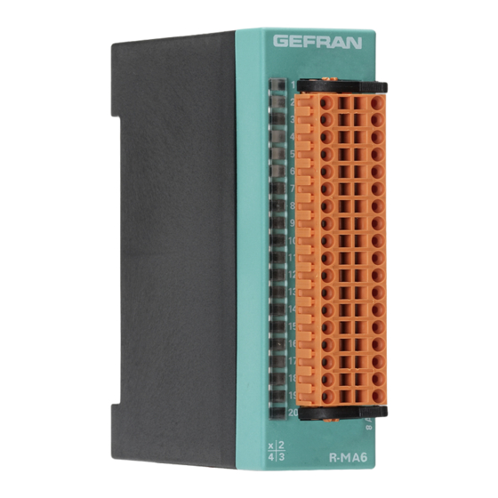
R-MA6
MODULE WITH 6 ANALOG INPUTS + 6 ANALOG OUTPUTS
INSTALLATION AND OPERATION MANUAL
cod. 80130D / Edit 05 - 08/09 - ENG
1 • MAIN FEATURES
I
2 • INSTALLATION AND CONNECTION
3 • TECHNICAL DATA
I
• 6 optically isolated analog outputs at 16 bit ±10V 20mA
• Electronic protection of the outputs
• Diagnostic LEDs
• CE MARKING: EMC Conformity (electromagnetic compatibility)
in accordance with EEC Directive 2004/108/CE. The GILOGIK II
system is mainly designed to operate in industrial environments,
installed on the switchboards or control panels of productive process
machines or plants.
Norm of applicable product EN 61131-2.
The Declaration of conformity is available on GEFRAN web:
www.gefran.com
• UL listed standard: UL508 file E198546
• BT Conformity (low tension)
in accordance with Directive LVD 2006/95/CE.
Inputs and outputs connection
• The externally connected circuits must be doubly isolated.
• To connect the analogue inputs the following is necessary:
- physically separate the input cables from those of the power supply, the
outputs and the power connections.
- use woven and screened cables, with the screen earthed in one point
only.
GEFRAN S.p.A. declines all responsibility for any damage
to persons or property caused by tampering, neglect,
improper use or any use which does not conform to the
characteristics of the controller and to the indications
given in these Instructions for Use.
Power supply for Inputs
24VDC ±25% 500mA max. external (fed to terminals)
• 10V for strain-gauge max 150mA
• 24V for amplified sensors max 500mA
Input isolation: > 2,0kV
Over-voltage on inputs for 1 ms maximum: max. 1kV
For UL: supply with class 2 device
Outputs
- Output power supply 24VDC ± 25% 500mA max
- Management of 6 analog outputs with conversion D/A to 16bit
- Settling time 100µs max.
- Voltage outputs ±10V, max. 20mA for channel
- Electronic protection against short-circuit and overload for each group of
3 channels: 100mA max.
- Linearity better than 0.5%
- Output isolation: > 2,0KV
- Over-voltage on inputs for 1 ms: maximum 1kV
80130D_MHW_R-MA6_0809_ENG
Advertisement
Table of Contents

Related Manuals for gefran R-MA6


Summary of Contents for gefran R-MA6
- Page 1 Before proceeding with installation read the following Norm of applicable product EN 61131-2. warnings carefully! The Declaration of conformity is available on GEFRAN web: Remember that lack of observation of these warnings www.gefran.com could lead to problems of electrical safety and electroma- •...
- Page 2 Green led RUN OUT5 OUT6 Red led FAIL R-MA6 The front connections of the module have: Power supplies 24Vdc ±25% 500mA max., use unipolar cable 0,75mm max., do not attach lug • Transducer inputs: potentiometer, use 3 pin shielded cable with 0.5 mm max. cross-section. Do not attach lug. Connect shielding directly to the grounded plate and as close as possible to the module.
- Page 3 Current Amplified sensor Strain-gauge 10V power supply 0...10V 0/4...20mA 24V power supply 10V power supply on board on board on board GEFRAN spa via Sebina, 74 - 25050 Provaglio d’Iseo (BS) Tel. 03098881 - fax 0309839063 - Internet: http://www.gefran.com 80130D_MHW_R-MA6_0809_ENG...
Need help?
Do you have a question about the R-MA6 and is the answer not in the manual?
Questions and answers