Table of Contents
Advertisement
Quick Links
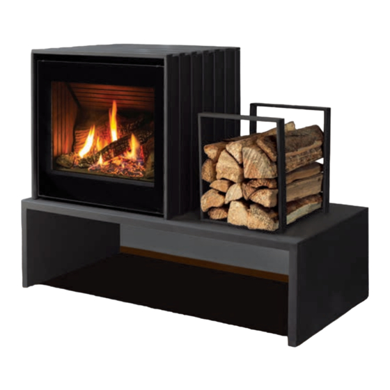
Cube
F R E E S T A N D I N G G A S F I R E P L A C E
OWNER'S MANUAL
WARNING:
If the information in this manual is not followed exactly, a
fire or explosion may result causing property damage, personal injury
or loss of life. Installation and service must be performed by a qualified
installer, service agency or the gas supplier.
C#4001609
CERTIFIED TO: ANSI Z21.88 / CSA 2.33 VENTED GAS FIREPLACE HEATERS
1
50-4315
CSA 2.17 GAS FIRED APPLIANCES FOR HIGH ALTITUDES
Version Française: www.enviro.com/fr.html
Advertisement
Table of Contents

Related Manuals for Enviro Cube


Summary of Contents for Enviro Cube
- Page 1 Installation and service must be performed by a qualified installer, service agency or the gas supplier. C#4001609 CERTIFIED TO: ANSI Z21.88 / CSA 2.33 VENTED GAS FIREPLACE HEATERS 50-4315 CSA 2.17 GAS FIRED APPLIANCES FOR HIGH ALTITUDES Version Française: www.enviro.com/fr.html...
-
Page 2: Safety Precautions
Safety Precautions WARNING: FIRE OR EXPLOSION HAZARD Failure to follow safety warnings exactly could result in serious injury, death, or property damage. - Do not store or use gasoline or other flammable vapors and liquids in the vicinity of this or any other appliance. - WHAT TO DO IF YOU SMELL GAS •... - Page 3 • Do not abuse the glass by striking it or slamming the door shut. TO TOUCH GLASS. • If the Cube unit is pulled out of its installation, and the vent- A barrier designed to reduce the risk of burns from the...
-
Page 4: Table Of Contents
Table of Contents Safety Precautions ........................2 Table of Contents ........................4 Codes And Approvals ........................6 Specifications ..........................7 Dimensions ............................7 Rating Label Location ........................8 Operating Instructions ........................ 9 Pilot Lighting Instructions ........................9 Air Shutter ............................10 Normal Sounds During Operation ......................10 Remote Control Operations ......................11 System Description ..........................11... - Page 5 Table of Contents Freestanding Drafthood Adaptor - (50-841 & 50-4176) ...............35 Gas Line Connection and Testing ......................39 Electrical Requirements ........................40 Secondary Installation ......................41 Installation of Optional Fan Kit (50-4304) ..................41 Installation of Log Set and Embers ....................41 Installation of Optional Panel Set (50-1038)..................44 Removal of Safety Screen .........................45 Trouble Shooting ........................
-
Page 6: Codes And Approvals
This appliance has been tested by INTERTEK and found to comply with the established VENTED GAS FIREPLACE HEATER standards in CANADA and the USA as follows: VENTED GAS FIREPLACE HEATER (Cube; NG/LPG) TESTED TO: ANSI Z21.88 / CSA 2.33 VENTED GAS FIREPLACE HEATERS CSA 2.17 GAS FIRED APPLIANCES FOR HIGH ALTITUDES... -
Page 7: Specifications
(CO) poisoning and possible death. imensions 23 - 3/4” 21 - 3/8” [603mm] [543mm] 21” [533mm] 22 - 3/8” 35” 19 - 3/8” [568mm] [889mm] [492mm] ELECTRICAL 3 - 7/8” [98mm] 24” 17 - 7/8” [610mm] [454mm] Figure 1: Cube Exterior Dimensions - Table... -
Page 8: Rating Label Location
[22 mm] [889 mm] [492 mm] 12 - 1/2” [318 mm] 44” [1118 mm] Figure 2: Cube Exterior Dimensions - Long Table ating abeL ocation The Rating Label is located on a plate hanging on the back left of the unit. -
Page 9: Operating Instructions
Operating Instructions For Your Safety, Read Safety Precautions And Lighting Instructions Before Operating WARNING: IF YOU DO NOT FOLLOW THESE INSTRUCTIONS EXACTLY A FIRE OR EXPLOSION MAY RESULT, CAUSING PROPERTY DAMAGE, PERSONAL INJURY OF LOSS OF LIFE. iLot ighting nstRuctions FOR YOUR SAFETY READ BEFORE OPERATING WARNING: IF YOU DO NOT FOLLOW THESE INSTRUCTIONS EXACTLY, A FIRE OR EXPLOSION... -
Page 10: Air Shutter
PeRation Table 2: Normal Sounds Component Sound & Reason Cube Creaking when heating up or cooling down. Burner Light pop or poof when turned off; this is more common with LP units. Temperature Sensor Clinking when it senses to turn the blower on or off. -
Page 11: Remote Control Operations
PeRations Proflame 2 is a modular remote control system that directs the functions of the Cube. The Proflame 2 TMFSLA is configured to control the on/off main burner operation, its flame levels and provides on/off and Smart thermostatic control of the appliance. The system also controls the fan speed through six (6) levels. -
Page 12: Integrated Fireplace Controller (Ifc)
Operating Instructions Key Lock Transmission Low battery alarm Thermostat OFF/ Room ON/SMART Temperature CPI mode Set Point Aux ON Temperature/Level/State Flame ON Split Flow Dimmer ON Comfort fan Figure 6: Proflame 2 Transmitter LCD Screen. (iFc) ntegRateD iRePLace ontRoLLeR The Proflame 2 IFC (Figure 7) connects directly to the gas valve, split flow valve, stepper motor, pilot and convection fan with a wiring harness. -
Page 13: Operating Procedure
When the Cube is turned off press the mode key to index to the constant pilot (CPI) mode icon (see Figure 9). Pressing the up arrow key will select Continuous Pilot Ignition (CPI) and pressing the down arrow key will return to IPI. - Page 14 Figure 12: Remote Control’s Flame Levels. Fan Control (if equipped) The Cube has an optional convection fan kit that can be controlled with the Transmitter. The fan speed can be adjusted through six (6) speeds. To control the fan press the Mode key to index to the fan control icon.
- Page 15 Operating Instructions Auxiliary Control This function is not used on the Cube and can be disregarded. Figure 14: Auxiliary Control (not used) Dimmer Control This function is not used on the Cube and can be disregarded. Figure 15: Dimmer Control Key lock This function will lock the keys to avoid unsupervised operation.
-
Page 16: Maintenance And Service
Do not operate with the glass front removed, cracked or broken. Removal and replacement of the glass from the door must be done by a licensed or qualified service person. The glass must be purchased from an ENVIRO dealer. No substitute materials are allowed. -
Page 17: Back Cover And Top Plate Removal
Maintenance And Service Figure 18: Safety Screen Removal Figure 19: Outer Glass Removal oveR anD Late emovaL Turn the unit off and wait for it to fully cool down before proceeding. Remove the screen and outer glass to allow access to the glass door (see section “Screen and Outer Glass Removal” on page 16). The back cover is secured to the unit with four (4) #8 T20 screws, two on each side. -
Page 18: Side Panel Removal
Maintenance And Service aneL emovaL Turn the unit off and wait for it to fully cool down before proceeding. Remove the screen and outer glass to allow access to the glass door (see section “Screen and Outer Glass Removal” on page 16). Remove the back cover and top plate as shown in section “Back Cover and Top Plate Removal”... -
Page 19: Fuel Conversion
The installation is not proper or complete until the operation of the converted appliance is checked as specified in the manufacturer’s instructions supplied with the kit. Kit Parts List for all Cube IPI models: 1 - Orifice (NG: #39) or (LP: #53) 1 - Pilot Orifice (NG: 0.2) or (LP: 0.14) - Page 20 Maintenance And Service 6. Convert the burner orifice: a. Remove the main burner orifice with a 1/2” socket b. Put a bead of pipe-thread sealant into the orifice mount. DO NOT OVER-TIGHTEN c. Install the new orifice: 7. Convert the SIT gas valve: a.
-
Page 21: Initial Installation
Initial Installation QUALIFIED INSTALLERS ONLY Warning: Operation of this heater when not connected to a properly installed and maintained venting system can result in carbon monoxide (CO) poisoning and possible death. RePaRation nstaLLation • Remove the packaging from the appliance, and check to make sure there is no damage. If damage is found, please report it to both the carrier and your dealer as soon as possible. - Page 22 Initial Installation QUALIFIED INSTALLERS ONLY Your total vent pipe length must be within the Round Support shaded area of Figure 34. If a 90° elbow is used Box/Wall Thimble in the horizontal plane, 36” (91.4 cm) must be subtracted from the allowable horizontal run. There are three (3) permitted types of Direct Vent System installations: horizontal (Figure 29), vertical Horizontal...
-
Page 23: Vent Termination Restrictions
Initial Installation QUALIFIED INSTALLERS ONLY eRmination estRictions Fixed Closed Fixed Openable Closed Openable Termination Cap Air Supply Inlet Gas Meter Restriction Zone (Termination not allowed) Figure 32: Vent Termination Restrictions, refer to Table 3. Table 3: Vent termination clearances, refer to Figure 32. Letter Canadian Installation US Installation... -
Page 24: Approved Vent Parts
Initial Installation QUALIFIED INSTALLERS ONLY PPRoveD aRts WARNING: Do not mix parts from different vent manufacturers’ systems. EXCEPTION TO WARNING: This product has been evaluated by Intertek for using a DirectVent Pro starting collar in conjunction with other venting systems. Use of this system with the DirectVent Pro starting collar is deemed acceptable and does not affect the Intertek listing of the appliance. -
Page 25: Vent Configurations
Initial Installation QUALIFIED INSTALLERS ONLY onFiguRations Figure 34 & Figure 35 show the range of venting options, they show possible vent configurations if the unit is top vented (see Figure 34) or rear vented (see Figure 35), for vertical and horizontal terminations, any layout that remains within the shaded area is acceptable. -
Page 26: Restrictor Settings
The ENVIRO CUBE has been designed with a built in restrictor plate. The restrictor is designed to enhance flame appearance when installing this unit with vertical chimneys as well as installations with longer horizontal vent applications. It does this by controlling the amount of air moving through the vent pipe. -
Page 27: Horizontal Installation
Initial Installation QUALIFIED INSTALLERS ONLY oRizontaL nstaLLation 1. Set the appliance in the desired location. Check to determine if wall studs or roof rafters are in the way when the venting system is attached. If this is the case, you may want to adjust the location of the appliance. - Page 28 Initial Installation QUALIFIED INSTALLERS ONLY NOTES: (a) The four (4) wood screws provided should be replaced with the appropriate fasteners for stucco, brick, concrete, or other types of siding. (b) For buildings with vinyl siding, a vinyl siding standoff, should be installed between the vent cap and the exterior wall (see Figure 40).
-
Page 29: Vertical Installation
Initial Installation QUALIFIED INSTALLERS ONLY eRticaL nstaLLation 1. Check the instructions for required clearances (air spaces) to combustibles when passing through ceilings, walls, roofs, enclosures, attic rafters, or other nearby combustible surfaces. Do not pack air spaces with insulation. 2. Set the gas appliance in the desired location. Drop a plumb bob down from the ceiling to the position of the appliance flue exit, and mark the location where the vent will penetrate the ceiling. - Page 30 Initial Installation QUALIFIED INSTALLERS ONLY 7. Slip the flashing over the pipe section protruding through the roof. Secure the base of the flashing to the roof with roofing nails. Use a non-hardening sealant between the uphill edge of the flashing and the roof. Insure the roofing material overlaps the top edge of the flashing as shown in Figure 43.
-
Page 31: Cathedral Ceiling Installation
Initial Installation QUALIFIED INSTALLERS ONLY Nails Ceiling firestop plumber’s tape connected to wall strap Ceiling Wall strap Use clearances to as defined by appliance and vent pipe manufacturers. 45° elbows (x2) Second floor Figure 46: Multi-Story Vent Pipe Installation. Figure 45: Use of Wall Straps. atheDRaL eiLing nstaLLation... -
Page 32: Corner Installations
Initial Installation QUALIFIED INSTALLERS ONLY 5. Using tin snips, cut the “Support Box” from the top corners down to the roof line, and fold the resulting flaps over the roof sheathing (Figure 48). Before nailing it in to the roof, run a bead of non-hardening mastic around the top edges of the “Support Box”, to make a seal between the box and the roof. -
Page 33: Converting Top Vented Into Rear Vented
Initial Installation QUALIFIED INSTALLERS ONLY onveRting enteD into enteD This unit can be converted to a rear vented unit with a 36” (915mm) snorkel for some installation applications. To convert this unit to a rear vented model, the flue pipe adapter must be turned to the rear vent position: 1. -
Page 34: Installation Of Rear Vented Appliance
Initial Installation QUALIFIED INSTALLERS ONLY nstaLLation oF enteD PPLiance 1. Place the unit into position. Minimum vent terminal 36" 2. Attach a small section of pipe on the unit and mark exterior (91.4cm) high snorkel kit. wall where vent would pass through the wall. Siding 3. -
Page 35: Installation Of Top Vented; Vertical Termination
DaPtoR This Drafthood Adaptor is a complete assembly and is ready to fit onto the Cube in a vertical vent application only. With the Drafthood Adaptor correctly installed and wired to the IFC the Cube may be vented like a B-Vent Fireplace. - Page 36 Initial Installation QUALIFIED INSTALLERS ONLY DRAFTHOOD WIRING: In order to connect the Drafthood Adaptor to the IFC the spill switch wires must first be modified as instructed below. Step 1: Cut off the connectors from the one end of the wires.
- Page 37 Initial Installation QUALIFIED INSTALLERS ONLY VENTING OF A FIREPLACE FITTED WITH THE DRAFTHOOD ADAPTOR: Note: Please refer to the chimney manufacturer’s installation instructions prior to commencing the installation. This unit may be vented to an existing masonry chimney, or where no masonry chimney is available, an approved “B-vent”...
- Page 38 Initial Installation QUALIFIED INSTALLERS ONLY AUTOMATIC SAFETY SHUT DOWN: If the spill switch is activated and shuts off the main burner the following procedure should be followed. • Is the pilot flame still on? If not, the reason for the fireplace shut down is not the spill switch. •...
-
Page 39: Gas Line Connection And Testing
Initial Installation QUALIFIED INSTALLERS ONLY onnection anD esting WARNING: Only persons licensed to work with gas piping may make the necessary gas connections to this appliance. GAS LINE CONNECTION • This stove is equipped with a certified flexible pipe located on the right side of the unit terminating in a ⅜”... -
Page 40: Electrical Requirements
Initial Installation QUALIFIED INSTALLERS ONLY LectRicaL equiRements The fireplace must be electrically connected and grounded in accordance with local codes or, in the absence of local codes, with the current CSA C22.1 Canadian Electrical Code Part 1, Safety Standards For Electrical Installations, or The National Electrical Code ANSI / NFPA 70 in the US. -
Page 41: Secondary Installation
If over time, through cleaning and servicing, these embers require replacement, contact the nearest ENVIRO dealer replacement embers. Note: Log set shown with optional panel set (50-1038) installed. Figure 67: Step 2 of Log Placement. - Page 42 Secondary Installation 1. Carefully remove logs from box. Check to ensure there is no damage. It is very important to install all logs in their proper position to insure safe, optimum operating conditions. 2. Place the log set into the firebox. Locate each log by seating it down onto the burner tray support pins.
- Page 43 ENVIRO dealer. See section “Cleaning The Glass” on page 16 Figure 71: Log Placement with Rock Wool.
-
Page 44: Installation Of Optional Panel Set (50-1038)
Secondary Installation (50-1038) nstaLLation oF PtionaL aneL Do not install when the unit is hot. The panel set is fragile. Handle panels with care and avoid knocking them on the placement pins or any other object. Figure 74: Panel bracket, slots shown. 1. -
Page 45: Removal Of Safety Screen
Secondary Installation emovaL oF aFety cReen If necessary, the safety screen can be removed from its assembly for cleaning or replacement by following the steps below. 1. Turn off the stove and allow it to fully cool down. Remove the safety screen assembly from the unit. Refer to section “Screen and Outer Glass Removal” on page 16 Lay the screen assembly face down on a soft surface to prevent scratching the paint. -
Page 46: Trouble Shooting
Trouble Shooting Problem Possible Cause Solution The main burner does not The gas valve may not be on. • Check that the gas control knob is in the “ON” position. ignite when called for. Thermostat is not calling for • Adjust the thermostat several degrees above ambient heat. -
Page 47: Parts List
Cube Venturi Adjustment Rod 50-4314 S.I.T. 885 Valve w/NG Stepper Motor 50-2682 Westport Burner Assembly 30-055 Cube IPI Fan Kit 150 CFM - SIT 50-4304 PSE IPI Pilot Assembly (2021) 50-4058 IPI Pilot Orifice (2021) 50-4080 Blank Orifice #73 - All Gas Models... -
Page 48: Parts Diagram
Parts Diagram... - Page 49 Sherwood Industries Ltd. (“Sherwood”) hereby warrants, subject to the terms and conditions herein set forth, this product against defects in material and workmanship An expanded list of exclusions is available at www.enviro.com/help/warranty.html during the specified warranty period starting from the date of original purchase at retail.
-
Page 50: Installation Data Sheet
� _________________________________________ NATURAL GAS (NAT) PROPANE(LPG) _________________________________________ INLET GAS PRESSURE:_________in wc PHONE:___________________________________ MAIN BURNER ORIFICE:__________# DMS PILOT ORIFICE #_________OR________in diam. INSTALLER’S SIGNATURE: _________________________________________ MANUFACTURED BY: SHERWOOD INDUSTRIES LTD. 6782 OLDFIELD RD. SAANICHTON, BC, CANADA V8M 2A3 www.enviro.com Winter 2023 C-16737...
Need help?
Do you have a question about the Cube and is the answer not in the manual?
Questions and answers