Table of Contents
Advertisement
Quick Links
ETP SRB81-3400-25-HA-D
Printed Matter No. 9839 1652 01
Publication Date 2020-07-16
Valid from Serial No. A1740001
Valid to Serial No. A2639999
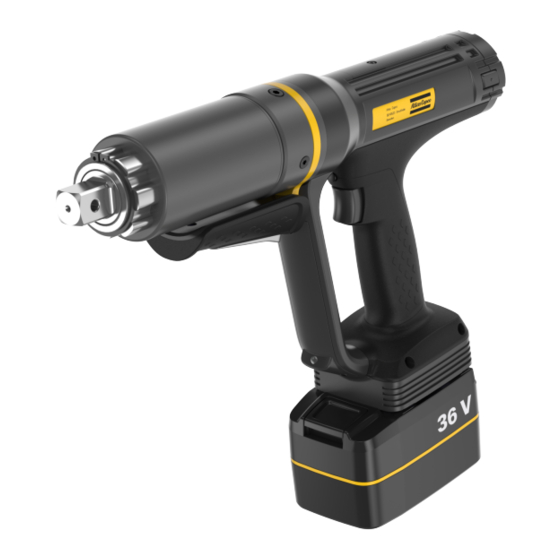
ETP SRB81-3400-25-HA-D
(1020-3400 Nm)
Read all safety warnings and instructions
Failure to follow the safety warnings and instructions may result in
electric shock, fire and/or serious injury.
Save all warnings and instructions for future reference
8433250001
WARNING
Battery-Powered Nutrunner
Product Instructions
Advertisement
Table of Contents

Related Manuals for Atlas Copco ETP SRB81-3400-25-HA-D


Summary of Contents for Atlas Copco ETP SRB81-3400-25-HA-D
- Page 1 ETP SRB81-3400-25-HA-D Printed Matter No. 9839 1652 01 Battery-Powered Nutrunner Publication Date 2020-07-16 Valid from Serial No. A1740001 Product Instructions Valid to Serial No. A2639999 ETP SRB81-3400-25-HA-D 8433250001 (1020-3400 Nm) WARNING Read all safety warnings and instructions Failure to follow the safety warnings and instructions may result in electric shock, fire and/or serious injury.
-
Page 2: Table Of Contents
RHMI ..................... 8 Service ........................ 10 Preventing ESD problems ................ 10 Maintenance Instructions................ 10 Service recommendations .............. 10 Dismantling/Assembling Instructions .............. 10 Dismantling.................. 10 Assembling .................. 16 Troubleshooting.................... 22 Overheated tool .................... 22 Recycling ....................... 23 Environmental Regulations................ 23 Recycling information .................. 23 © Atlas Copco Industrial Technique AB - 9839 1652 01... -
Page 3: Product Information
■ Damage to parts that occurs as a result of inadequate maintenance or performed by parties other than Atlas Copco or their Certified Service Partners during the warranty period is not covered by the warranty. ■ To avoid damage or destruction of tool parts, service the tool according to the recommended mainte- nance schedules and follow the correct instructions. -
Page 4: Servaid
Please consult the Atlas Copco website for more information www.atlascopco.com/sds. Product safety video for nutrunners Learn more about safety features on Atlas Copco nutrunners and what measures the operator has to take for a safe operation. Click the link or scan the QR code below to view the video: https://www.youtube.com/watch?v=FAh6yttvUpw... -
Page 5: Service Overview
If the product is not working properly, take it out of service and inspect it. If no detailed information about preventive maintenance is included, follow these general guidelines: ■ Clean appropriate parts accurately ■ Replace any defective or worn parts © Atlas Copco Industrial Technique AB - 9839 1652 01... -
Page 6: Installation
To remove the battery pack, press the button on the battery and push it out. Since a battery pack slowly discharge itself, keep the battery pack in the charging unit that provides a trickle charge. © Atlas Copco Industrial Technique AB - 9839 1652 01... -
Page 7: Operation
Check that the tool is in the correct running direction by turning the reverse button or reverse ring : Pistol Grip Models (with side buttons) ■ Press in the reverse switch on the right hand side of the tool, to set the direction clockwise (CW). © Atlas Copco Industrial Technique AB - 9839 1652 01... -
Page 8: Special Precaution
If the tool starts; stop work. RHMI Overview Navigation button Display screen Confirmation button ■ short press to confirm selection ■ long press to go back to previous menu Navigation button © Atlas Copco Industrial Technique AB - 9839 1652 01... - Page 9 ■ Configuration Configure tool button, front light settings, enable/disable web-HMI(only available for -HA and -HA-X tools in smart mode). ■ Tightening results Show a list of the last tightening results. © Atlas Copco Industrial Technique AB - 9839 1652 01...
-
Page 10: Service
Turn the locking ring and pull out the front gear. Dismantling the Dual Trigger Remove the locking screw. Slightly turn the dual trigger to uncover the screw on the front lid. © Atlas Copco Industrial Technique AB - 9839 1652 01... - Page 11 Dismantling the Power Module Remove the screws and pull out the power module. Dismantling the HMI Remove the screws and the back cover. Pull out the HMI and detach the cable. © Atlas Copco Industrial Technique AB - 9839 1652 01...
- Page 12 Use pliers to remove the locking pin. Remove the start trigger. Dismantling the Function Button and Configuration Board Lift the function button from the slot to remove it. Lift the configuration board to remove it. © Atlas Copco Industrial Technique AB - 9839 1652 01...
- Page 13 Remove the screws, followed by the internal gear and the intermediate shaft. Remove the screws to be able to pull out the gear identification board. Dismantling the Front Bearing Shield Remove the screws to remove the bearing shield. © Atlas Copco Industrial Technique AB - 9839 1652 01...
- Page 14 Dismantling the Commutation Board Remove the screws. Remove the locking ring to remove the commutation board. Dismantling the Commutation Magnet Use plier 4080 1180 80 to grab and remove the commutation magnet. © Atlas Copco Industrial Technique AB - 9839 1652 01...
- Page 15 Remove the locking screw. Remove the bearing shield. Dismantling the Accessory Board Remove the screw. Remove the accessory lid. Remove the screw. Pull out the accessory board and disconnect the cable. © Atlas Copco Industrial Technique AB - 9839 1652 01...
-
Page 16: Assembling
Tighten the screw on the accessory board Tighten the screw on the lid. Assembling the Rear Bearing Insert the bearing shield. Tighten the locking screw. Assembling the Commutation Magnet Insert the commutation magnet. © Atlas Copco Industrial Technique AB - 9839 1652 01... - Page 17 Tighten the screws to fasten the locking ring. Assembling the Front Bearing Shield Insert the wave spring. Install the bearing shield. And feed the cable through the channel to be able to attach it. Tighten the screws. © Atlas Copco Industrial Technique AB - 9839 1652 01...
- Page 18 Tighten the screw to fasten the main board. Assembling the Function Button and Configuration Board Insert the configuration board and attach the cable. Insert the function button into the slot. © Atlas Copco Industrial Technique AB - 9839 1652 01...
- Page 19 Slightly press the trigger (A) and insert the locking pin (B) with pliers. Assembling the Handle Tighten the screws to attach the handle. Assembling the HMI Install the HMI and attach the cable. Install the back cover and fasten the screws. © Atlas Copco Industrial Technique AB - 9839 1652 01...
- Page 20 Attach the cables on the front lid. Tighten the screws to fasten the front lid. Turn the dual trigger to the correct position. Tighten the locking screw of the trigger. © Atlas Copco Industrial Technique AB - 9839 1652 01...
- Page 21 ETP SRB81-3400-25-HA-D Service Assembling the Front Gear Install the front gear and turn the locking ring to the correct position. Tighten the screw. © Atlas Copco Industrial Technique AB - 9839 1652 01...
-
Page 22: Troubleshooting
The tool can handle any normal line jobs that an operator sustains with the proper adjustments. The tool temperature can be influenced by the following parameters: ■ torque above rated ■ too low speed ■ very high prevailing torque ■ very soft joints ■ short cycle time © Atlas Copco Industrial Technique AB - 9839 1652 01... -
Page 23: Recycling
Metal, aluminium and steel Accessory board Electronics Screw Metal, steel Accessory lid Metal, aluminium Screw Metal, steel Rotor Metal, Neodymium Rear bearing shield Metal, aluminium Screw Metal, steel Commutation board Electronics © Atlas Copco Industrial Technique AB - 9839 1652 01... - Page 24 Dual trigger base Metal, Zinc Switch Electronics Spring Metal, steel Metal, steel Trigger holder Metal, steel Screw Metal, steel Spring Metal, steel Trigger Metal, steel Dual trigger grip Plastic, other, PA © Atlas Copco Industrial Technique AB - 9839 1652 01...
- Page 28 Original instructions © Copyright 2020, Atlas Copco Industrial Technique AB. All rights reserved. Any unauthorized use or copying of the contents or part thereof is prohibited. Atlas Copco Industrial This applies in particular to trademarks, model denominations, part numbers Technique AB and drawings.
Need help?
Do you have a question about the ETP SRB81-3400-25-HA-D and is the answer not in the manual?
Questions and answers