Table of Contents
Advertisement
Quick Links
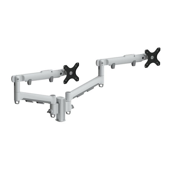
Dual Dynamic Arm Mount F clamp
COMPONENT CHECKLIST
AWM-FF
F Clamp
(x1)
CONTENTS
F Clamp
Page 2
135 Post
Page 3
Channel Clamp
Page 4
Dynamic Arm
Page 5
IMPORTANT INFORMATION
! Please ensure this product is installed as per these installation instructions.
! Do not remove/ throw away the plastic cap on channel clamp and arm links.
! This product is compatible with Atdec AWM Series products.
! Product must only be installed on a solid work surface capable of supporting the weight of all equipment being mounted.
! Curved monitors, deep devices (such as all-in-one PCs) and offset VESA locations exert additional leverage that can exceed
the capacity of the mount even though the monitor weight may be within the stated range.
! The manufacturer accepts no responsibility for incorrect installation.
AWM-P13
AWM-LC
135 Post
Channel
(x1)
Clamp
AWM-FF
Component Checklist + Clamp Installation
AWM-P13
Component Checklist + Post Installation
AWM-LC
Component Checklist + Clamp Installation
AWM-AD
Component Checklist + Arm Installation
AWM-AD
Dynamic
Arm
(x2)
Installation Guide
AWMS-2-D13-F
RANGE
REQUIRED TOOLS
• Phillips Head
Screwdriver
(x2)
May be supplied as:
AWM-ADC
AWMS-2-D13-F Page 1 of 7
Advertisement
Table of Contents

Related Manuals for Atdec AWMS-2-D13-F


Summary of Contents for Atdec AWMS-2-D13-F
- Page 1 ! Do not remove/ throw away the plastic cap on channel clamp and arm links. ! This product is compatible with Atdec AWM Series products. ! Product must only be installed on a solid work surface capable of supporting the weight of all equipment being mounted.
- Page 2 (1 3/8” - 3”) behind the worksurface, perform Step 3.1 before this step. 3. Fit fixing to work surface 3.1 Place in desired location 3.2 Screw in on worksurface pressure plate and tighten firmly. Mounting surface Hex Key AWMS-2-D13-F Page 2 of 7...
- Page 3 Load cables into cable in the other side. cover Cables can exit from the side of the cable cover AWMS-2-D13-F Page 3 of 7...
- Page 4 2.3 Place rotation ring in the desired position and replace plastic sleeve. NOTE: Place the rotation ring depending on what post channel the arm will be attached to. The tag should always face towards the user. 2. Lift Default Position 360° 1. Press 180° Flipped Position AWMS-2-D13-F Page 4 of 7...
- Page 5 100mm NOTE: Be sure to use a screw length that suits the monitor. 75mm 12mm 100mm 75mm Flush Spacer NOTE: For other sizes, use a suitable adaptor plate Too long Too short (sold separately). AWMS-2-D13-F Page 5 of 7...
- Page 6 Monitor Falls Monitor ‘Floats’ Monitor Springs (from top) (from bottom) (all positions) Increase Tension Reduce Tension Balanced AWMS-2-D13-F Page 6 of 7...
- Page 7 No portion of this document or any artwork contained herein should be reproduced in any way without the express written consent of Atdec Pty Ltd. Due to continuing product development, the manufacturer reserves the right to alter specifications without notice. ©20230119B...
Need help?
Do you have a question about the AWMS-2-D13-F and is the answer not in the manual?
Questions and answers