Table of Contents
Advertisement
Quick Links
Advertisement
Table of Contents

Summary of Contents for Hofmann MC10 HS
- Page 1 Operator’s Manual Unbalance measuring system MC10 HS Ref. No. 025329 025330-251-de Rev. 1.3 202008 025330 Translation of Original Operator’s Manual Hofmann Mess- und Auswuchttechnik GmbH & Co. KG I 64319 Pfungstadt I Germany I www.hofmann-global.com...
- Page 2 All rights reserved. No part of this document may be reproduced in any form (print, photocopy, microfilm or by any other means) nor stored, manipulated, copied or distributed by electronic sy- stems without written permission from Hofmann Mess- und Auswuchttechnik GmbH & Co. KG. Keep Operator’s Manual in a safe place for future use.
-
Page 3: Table Of Contents
MC10 HS Table Of Contents Table of Contents General Instructions ............1 - 1 Manufacturer and Designation . - Page 4 Table of Contents MC10 HS Displays .............4 - 24 4.9.1...
- Page 5 MC10 HS Table Of Contents Glossary ..............7 - 1 Technical specifications .
- Page 6 Table of Contents MC10 HS...
-
Page 7: General Instructions
EC declaration of conformity and for it to carry the CE label. The unbalance measuring system was built by: Hofmann Mess- und Auswuchttechnik GmbH & Co. KG, Werner-von-Siemens-Straße 21 D-64319 Pfungstadt and its full designation is: Unbalance measuring system MC10 HS ... -
Page 8: Industrial Property Rights
- Industrial Property Rights MC10 HS Industrial Property Rights The unbalance measuring system MC10 HS is the intellectual property of Hofmann Mess- und Auswuchttechnik GmbH & Co. All rights to the unbalance measuring system, the measuring principle, relevant drawings etc. are the property of the manufac- turer and are subject to the German copyright legislation "Gesetz... -
Page 9: Information Symbols
General Instructions MC10 HS - About this Manual 1.4.4 Information Symbols INFORMATION are used for additional information instructs you to act instructs you to carry out a step in a procedure shows how the machine will react ... - Page 10 General Instructions - About this Manual MC10 HS 1 - 4...
-
Page 11: Unbalance Measuring System
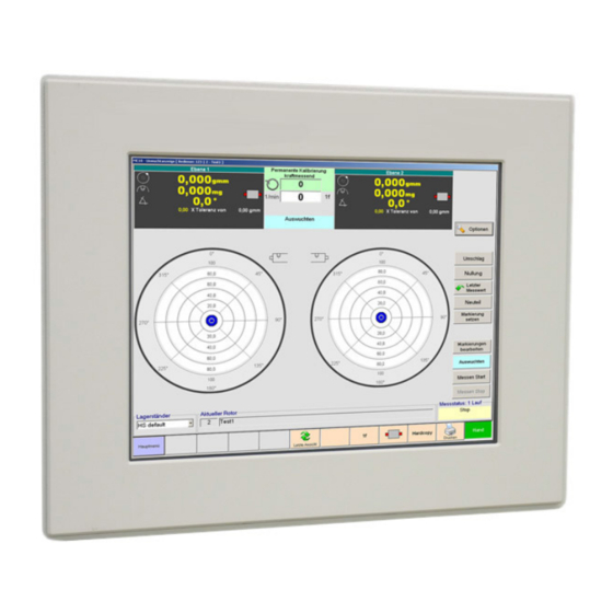
Unbalance measuring system MC10 HS - Features Unbalance measuring system The unbalance measuring system MC10 HS provides the latest touch screen technology for your application. The operational concept allows for simple set up and operation of your machine. For your tasks at hand, it is the first choice for precision balancing today and in the future. - Page 12 Unbalance measuring system - Features MC10 HS 2 - 2...
-
Page 13: Installation And Support
3.1.2 Software Installation The MC software is factory installed on the measuring computer. 3.1.3 Software Update Installation Software updates are installed by Hofmann service personnel. 3.1.4 Software Re-installation Software is re-installed by Hofmann service personnel. System Maintenance INFORMATION If the machine is operated around the clock, the unbalance meas- uring system should be shut down and restarted at least once a week, to free the memory of temporary Windows files. - Page 14 Installation and Support - System Maintenance MC10 HS 3 - 2...
-
Page 15: Basic Operation
Basic Operation MC10 HS - Operator Controls Basic Operation To work with the program, you should be familiar with the Windows environment. For questions regarding menu commands, dialogue boxes, scroll bars or oth- er elements of the user interface, please read the Windows literature. - Page 16 Basic Operation - Operator Controls MC10 HS To clean the touch screen ATTENTION Unplug power cord before cleaning device. Also refer to separate manufacturer's operator's manual. ATTENTION Ensure that no liquids enter through openings into the interior of the housing while cleaning.
-
Page 17: Screen Keypads
Basic Operation MC10 HS - Operator Controls 4.1.2 Screen Keypads Virtual keypads appear on the screen, when text or numbers need to be entered using your fingertip. To enter letters / numbers etc. Press the appropriate key area. Confirm with "Ok" or "Close". -
Page 18: Selection
Basic Operation - Operator Controls MC10 HS 4.1.3 Selection 4.1.3.1 Selection using keypads Press keypad. Selection is highlighted by colour. 4.1.3.2 Selection using drop-down menus Press down arrow. A menu pops up. Current selection is marked. -
Page 19: Operational Restrictions
Basic Operation MC10 HS - Operational Restrictions Operational Restrictions INFORMATION Some particular functions may be blocked for the cur- rently selected access group (Operator, Supervisor). The associated values and actions are greyed out. Refer to Chapter 5.6 - Access Privileges. -
Page 20: Main Menu
Basic Operation - Main Menu MC10 HS Main Menu On all program screens: Press the "Main Menu" key. The Main Menu appears: Fig. 4-1: Main Menu 4.4.1 "Operation" submenu Rotor database Create, change, copy, save... rotor data Unbalance Display... -
Page 21: Measure Settings" Submenu
Basic Operation MC10 HS - Main Menu 4.4.2 "Measure Settings" submenu Rotor setup Create and change rotor and correction data, enter units and tolerances Data acquisition setup Display and set parameters for data acquisition Calibration Display and set calibration parameters, perform cali- bration 4.4.3... -
Page 22: Unbalance Display
Basic Operation - Unbalance Display MC10 HS Unbalance Display After the program start or after pressing the "Unbal- ance Display" key, the unbalance display appears: Fig. 4-2: Unbalance Display 1 - Indication of unbalance amount and angle, type of calibration, direction of rotation, rotation-... - Page 23 Basic Operation MC10 HS - Unbalance Display Measuring status refer to table below Measuring status Manual / Automatic Manual or automatic mode. Measuring / Measuring Display of measurement status. complete / Stable In tolerance / Out of tole- Assessment of measurement rance / Correction required result.
-
Page 24: Displaying Unbalance
Basic Operation - Unbalance Display MC10 HS 4.5.1 Displaying Unbalance Amount and angle Magnitude of unbalance in unbalance and weight unit Unbalance location in degrees (°) Meaning of the different colours and numbers: Green Rotor unbalance in tolerance. -
Page 25: Setting The Display
Basic Operation MC10 HS - Unbalance Display 4.5.2 Setting the Display 4.5.2.1 Polar Graph Unbalance Display \ Options. Select "Polar Graph" tab. Change settings: Set 0° Position Select 0° position in the polar graph. Top / Bottom / Right / Left... -
Page 26: Indexing Indicator (Option)
Basic Operation - Unbalance Display MC10 HS 4.5.2.3 Display settings Unbalance Display \ Options. Select "Display Settings" tab. Enter values or change settings: Scaling Auto / Let scaling of the polar display User defined for both planes be adapted au-... -
Page 27: Command Keys
Basic Operation MC10 HS - Unbalance Display 4.5.4 Command Keys Name Function Meaning Options Command Open "Settings Polar Dis- play". Remount Command Perform remount balancing or read last value. "ON": "ON": Unbalance display with offsetting of zeroing value. Zeroing Command Zeroing ON / OFF "ON": Attention! The indica-... -
Page 28: Command Bar
Basic Operation - Unbalance Display MC10 HS 4.5.5 Command Bar The command bar features shortcuts for Main Menu commands on the left hand side. This area has a dif- ferent allocation depending on the display. Fig. 4-3: Command bar on the measuring screen... -
Page 29: Unbalance Plotting
Basic Operation MC10 HS - Unbalance plotting Unbalance plotting Curve shape Press the "Unbalance Plotting" key: Note "ATTENTION: Run-up / Run-down" is dis- played. Press "Curve" (A) key. Fig. 4-4: Unbalance plotting 1 - Indication of unbalance amount and angle,... - Page 30 Basic Operation - Unbalance plotting MC10 HS Indicator RH / LH rotation 1/min (RPM) Indicator Currently measured speed Indicator direct speed optional - double sample rate for diagnosis Current rotor Indication of currently selected rotor type Measuring status refer to table below...
-
Page 31: Setting The Plots
Basic Operation MC10 HS - Unbalance plotting 4.6.1 Setting the Plots 4.6.1.1 Display settings Unbalance Plotting \ Options. Select "Display Settings" tab. Change settings: Scaling Auto / Let scaling of the x-axis for both User defined graphs be adapted automatical- (top) ly or define as required. -
Page 32: Command Keys
Basic Operation - Unbalance plotting MC10 HS Polar graph Press the "Unbalance Plotting" key. Note "ATTENTION: Run-up / Run-down" is dis- played. Press "Polar" (A) key. Fig. 4-5: Unbalance plotting 1 - Indication of unbalance amount and angle,... - Page 33 Basic Operation MC10 HS - Unbalance plotting Current rotor Indication of currently selected rotor type Measuring status refer to table below Measuring status Manual / Automatic Manual or automatic mode. Measuring / Measuring Display of measurement status. complete / Stable...
- Page 34 Basic Operation - Unbalance plotting MC10 HS Enter values or change settings: No Filter Switch filter function on / off completely. Speed increment Selection and set-up of the filter function. Speed tolerance Only one of the four possible fil- Amplitude tolerance ters can be selected.
- Page 35 Basic Operation MC10 HS - Unbalance plotting 4.6.3 Command Keys Name Function Meaning Options Command Window for polar graph (only for polar), call up display set- tings and measurement ac- quisition. Load Measure- Load saved measurements ment into the unbalance plot.
- Page 36 Basic Operation - Unbalance plotting MC10 HS 4.6.4 Command Bar The command bar features shortcuts for Main Menu commands on the left hand side. This area has a dif- ferent allocation depending on the display. Fig. 4-6: Command bar on the measuring screen...
-
Page 37: Changing Settings
Basic Operation MC10 HS - Changing Settings Changing Settings Touch field that requires changing. The on-screen keyboard appears Delete value with "Del" key or and/or enter value with the keys. INFORMATION Values differing from the stored configuration appear in white characters on a red background. -
Page 38: Selecting Operating Language
Basic Operation - Selecting Operating Language MC10 HS Selecting Operating Language Press "Language" key in the command bar. The "Language" window appears. Press key indicating desired language. The "Language" window disappears. The currently active language is shown in the command bar. -
Page 39: Saving Data
Basic Operation MC10 HS - Saving Data 4.10 Saving Data INFORMATION Various data can be saved in PDF format locally to removable storage devices or to connected net- work drives. Example for rotor database Press the "Rotor Database" key. ... - Page 40 Basic Operation - Saving Data MC10 HS 4 - 26...
-
Page 41: Operation
Operation MC10 HS - Measuring Unbalance Operation INFORMATION The possibility to perform the following operational steps depends on the access privileges set for the re- spective access group. Measuring Unbalance Unbalance Display ATTENTION Do not leave the unbalance display during the auto- matic operation. -
Page 42: Editing Rotor Data
Operation - Editing Rotor Data MC10 HS Editing Rotor Data Access privileges may have to be activated by the supervisor. Expand list of rotors by 100 lines. Sort list of rotors alphabetically. 5.2.1 Selecting a Rotor Perform required re-tooling work. -
Page 43: Deleting A Rotor
Operation MC10 HS - Editing Rotor Data 5.2.4 Deleting a Rotor Main Menu \ Rotor Database. Mark the rotor, you want to delete. Press the "Delete Rotor" key and confirm by pressing "Yes". Press the "Close" key. -
Page 44: Exporting A Rotor
Operation - Editing Rotor Data MC10 HS 5.2.7 Exporting a Rotor Main Menu \ Rotor Database. Mark rotor to be exported. Press "Export" key. The Save dialogue appears. Select drive and location for saving. Enter file name. -
Page 45: Printing The Database
Operation MC10 HS - Editing Rotor Data 5.2.10 Printing the Database Main Menu \ Rotor Database. Press the "Print Database" key. The printing dialogue appears. If required, press "Configuration" key and se- lect printer. Press the "Print..." key. -
Page 46: Setup Rotor Data - Geometry
Operation - Editing Rotor Data MC10 HS 5.2.11 Setup Rotor Data - Geometry Main menu \ Rotor settings Select "Geometry" tab. Enter values or change settings: Rotor dimensions Enter dimensions of the rotor. Radius / Diameter Select diameter or radius. - Page 47 Operation MC10 HS - Editing Rotor Data 5.2.11.1 Enter simulation unbalance Press "Bias unbalance" key. The "Bias unbalance" table appears. Enter values: Weight, radius, angle Mass, radius and angle of simula- tion unbalance. Unbalance Resulting simulation unbalance.
-
Page 48: Setup Rotor Data - Units And Tolerances
Operation - Editing Rotor Data MC10 HS 5.2.12 Setup Rotor Data - Units and Toler- ances Main menu \ Rotor settings. Select "Units & Tolerances" tab. Enter values or change settings: Tolerance Setup Enter balancing tolerances and cor- rection limits. -
Page 49: Setup Rotor Data - Correction
Operation MC10 HS - Editing Rotor Data 5.2.13 Setup Rotor Data - Correction Main menu \ Rotor settings. Select "Correction" tab. Enter values or change settings: Unbalance Display Select polar or component cor- rection Indexing offset Offset correction position (grip- per) with respect to 0°-position... -
Page 50: Setup Rotor Data - Tasks
Operation - Editing Rotor Data MC10 HS 5.2.14 Setup Rotor Data - tasks INFORMATION The field can be used to enter retooling information for the currently selected rotor. Main menu \ Rotor settings. Select "Necessary Work" tab. Select function. -
Page 51: Setup Rotor Data - Measure Drive
Operation MC10 HS - Editing Rotor Data 5.2.15 Setup Rotor Data - Measure Drive Main menu \ Rotor settings. Select „Measure Drive 1" (or 2) tab. Enter values or change settings: Measure / Correct Choose Measure or Measure... -
Page 52: Setup Rotor Data - Measure Drive 3 / Turn Drive
Operation - Editing Rotor Data MC10 HS 5.2.16 Setup Rotor Data - Measure drive 3 / Turn Drive Main menu \ Rotor settings. Select „Measure Drive 3 / Turn Drive“ tab. Enter values or change settings:. Runup / Rundown... -
Page 53: Changing Settings
All parameters have a direct impact on the measure- ment data acquisition and, thus, on the measuring capability of the measurement electronics. Changes should only be carried out by Hofmann ser- vice personnel. 5.3.1.1 Measure Settings Main Menu \ Data Acquisition Setup. - Page 54 Operation - Changing Settings MC10 HS Measuring cycles setup Measure cycles Number of measuring runs dur- ing measurement Calibration cycles Number of measuring runs dur- ing calibration Index Bal. cycles Number of measuring runs dur- ing remount balancing Zeroing cycles...
-
Page 55: Changing Mc10 Settings
Operation MC10 HS - Changing Settings 5.3.2 Changing MC10 Settings 5.3.2.1 General MC10 settings Main Menu \ Setup MC10. Start actions, enter values or make settings: Configuration INFORMATION The configuration comprises all the settings of the un- balance measuring system and the interfaces to the balancing machine. - Page 56 Operation - Changing Settings MC10 HS Options Use OnScreen Keyboard Setting active: Use on-screen keyboard Setting not active: Use separate keyboard Confirm Termination Setting active: Confirm program end in a sepa- rate window. Setting not active: Quit program without special confirmation.
- Page 57 Operation MC10 HS - Changing Settings 5.3.2.2 MC10 settings EKS Main Menu \ Setup MC10 \ EKS. Change settings: INFORMATION This function is only available for the access group "Maintenance". Status KeyIn: Key inserted - field yel- KeyOut: Key not inserted - field...
-
Page 58: Calibrating
Operation - Calibrating MC10 HS Calibrating INFORMATION Refer to Calibration. 5.4.1 Carrying Out the Calibration The machine is ready for operation and set up on the calibration rotor. Main Menu \ Calibration. Select permanent calibration. Enter values: ... - Page 59 Operation MC10 HS - Calibrating INFORMATION By definition the 0° position is pointing from the cen- tre of the axis horizontally forward to the operator. Machine bed Operator side Index setting position for test weights Machine control: Manual \ Correction \ Data/Adjust.: Press "Turn Drive"...
-
Page 60: Remount Balancing (Option)
Operation - Remount Balancing (Option) MC10 HS Remount Balancing (Option) For universal shaft drive INFORMATION Refer to chapter 7 Remount balancing. Rotor data set has been created. The machine is ready for operation and set up on the rotor. -
Page 61: Deleting Tool Error Compensation Values
Operation MC10 HS - Remount Balancing (Option) Remove rotor. INFORMATION Remount balancing and the determination of tool er- ror compensation values is now complete. The tool error compensation values are included in the dis- played measurement values. 5.5.2 Deleting Tool Error Compensation Values Press "Index. -
Page 62: Access Privileges
Operation - Access Privileges MC10 HS Access Privileges Access groups Operator / Supervisor / Service MC10 always starts with the "Operator" access group. Colour change The access groups are assigned different colours. The colour of the currently selected access group is to be found in the writing on the label (1) and on the keys of the command bar (2). -
Page 63: Other Functions
Other Functions MC10 HS - Machine Performance Counters Other Functions Machine Performance Counters Counters available: Total Type-specific Job-specific Main Menu \ Machine Performance Counters To display the type-specific piece figures, se- lect the type. To display the job-specific piece figures, select ... -
Page 64: Job Management
Other Functions - Machine Performance Counters MC10 HS 6.1.4 Job Management Main Menu \ Machine Performance Counters. Press the "Job management..." key. Create a new job or Select an existing job or Delete a job. ... -
Page 65: Generating A Report
Other Functions MC10 HS - Generating a Report Generating a Report INFORMATION The report shows the initial unbalance (1. measure- ment) and the residual unbalance after a correction (2. measurement) for a rotor together with the rotor data and editable header data. -
Page 66: Editing The Print List
Other Functions - Generating a Report MC10 HS 6.2.5 Editing the Print List Select "Print list" tab. Delete individual or all list entries as required. Press the "Apply" key. 6.2.6 Printing a Multiple Report Select "Print list" tab. -
Page 67: Viewing And Managing System Information
Other Functions MC10 HS - Viewing and Managing System Information Viewing and Managing System Information 6.3.1 System Diagnostics Main Menu \ System Diagnostics Possible actions: Displaying System Information Date and Time Date and time for printouts etc. are obtained from the ©... - Page 68 Other Functions - Date and Time MC10 HS 6 - 6...
- Page 69 Glossary MC10 HS Glossary Calibration The basics With calibration, the sensitivity of the unbalance measuring sys- tem is adjusted to the signals of the encoders in the machine. The signal magnitudes and phases are assigned to the calibration un- balances, which are attached to the test rotor.
- Page 70 Glossary MC10 HS rotor (weight and dimension). It must, however, be guaranteed that the attachment radius and attachment angle can be precisely matched. Machine Calibration With this calibration, the specific parameters of the measuring device are determined. The installation of the machine, the components of the measuring device, such as the encoders and springs, and the test rotor used all effect the values measured.
- Page 71 Glossary MC10 HS Predefined unbalance In some areas of balancing technology, it is necessary to work with simulation unbalances in serial balancing in order to simu- late unbalances, which occur when the workpiece is in practical use, e.g. screws, feather keys (half cylinder) and other connect- ing and attachment parts.
- Page 72 Glossary MC10 HS 7 - 4...
- Page 73 Technical specifications MC10 HS - Software Technical specifications Software Version............MC10 3.20 Computer Specifications RAM..............min. 128 MB Hard disk............. min. 40 GB Operating system....WINDOWS XP Professional Measuring Equipment Measuring range..........60 - 6,000 rpm Electrical Equipment Mains voltage (10%) ..........230 V Mains frequency ............
- Page 74 Technical specifications - Electrical Equipment MC10 HS 8 - 2...
Need help?
Do you have a question about the MC10 HS and is the answer not in the manual?
Questions and answers