
Related Manuals for Rittal DK 7320.100


Summary of Contents for Rittal DK 7320.100
-
Page 1: Documentation Notes
CMC-TC Processing Unit II DK 7320.100 Assembly, Installation and Operation A29290 28 IT 74... - Page 2 Microsoft Windows is a registered trademark of Microsoft Corporation. Acrobat Reader is a registered trademark of Adobe Systems Incorporated.
-
Page 3: Table Of Contents
Documentation Notes 1 7.3.7 Configuring the NTP......18 Table of Contents 7.3.8 Configuring the PPP......19 Documentation Notes ....... 5 7.3.9 Configuring the Sending of E-Mails .. 19 Associated Documents......5 7.3.10 Configuring the System Name, Contact CE Certification........5 and Location........19 Retention of the Documents ....5 7.3.11 Configuring the Passwords .... - Page 4 1 Documentation Notes 7.7.10 Configuring the Motion Detector..34 7.15 Access Control Using an External Access File ........50 7.7.11 Configuring the Digital Input Module .34 7.7.12 Configuring the Digital Output Relay Maintenance and Cleaning .....51 Module ..........35 8.1.1 Cleaning ..........51 7.7.13 Configuring Switching Combinations for Storage and Disposal......51 the Digital Relay Output Module..35...
-
Page 5: Documentation Notes 1
Other tasks associated with the CMC-TC PU, accessible for subsequent use. such as the assembly and installation of system Rittal cannot accept any liability for damage and components with tested standard connectors, and operational malfunctions that result from the non- the operation and configuration of the CMC-TC PU observance of this guide. -
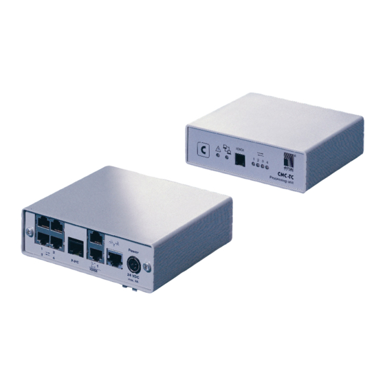
Page 6: Unit Description
DHCP (Dynamic Host Configuration Protocol) Optionally, the CMC-TC PU can also communicate using a Master Unit or using an ISDN or GSM unit. Associated information is available at the Rittal ho- me page (www.rittal.com) or in Catalogue 31. CMC-TC Processing Unit II... -
Page 7: Connectable Sensors
DK 7320.500 ser and is operating-system-independent. Humidity sensor DK 7320.510 The number of Rittal CMC-TC Processing Units in the network is unlimited, provided adequate free IP Analog sensor input mod- DK 7320.520 addresses are available in the network. If this is not ule "4 –... -
Page 8: Accessories
3 Unit Description 3.7 Accessories Number Designation 3.7.1 Required Accessories CMC-TC Processing Unit with net- Depending on the country-specific specifications, work interface RJ -45 socket (10/100 you require an appropriate connection cable for the BaseT) power pack of the CMC-TC PU. Self-adhesive Velcro fasteners Acces- Model... -
Page 9: Optional Accessories
A use different from that described here is consid- ered to be an improper use. Rittal cannot accept any liability for damage resulting from the improper use or the non-observance of this guide. The guides for the used accessories may apply. -
Page 10: Assembly
4 Assembly Assembly • Attach the Velcro fasteners to the housing of the CMC-TC PU and position the CMC-TC PU at the 4.1 Assembly notes required attachment location. Install the CMC-TC PU in an enclosure or in a suit- able housing system so that it also has additional protection from external effects. -
Page 11: Installation 5
5.1 Safety and other notes Fig. 7 Pin assignment (plug) − The Rittal CMC-TC Processing Unit may be op- erated only with connected protective earth con- ductor. The protective earth conductor connec- Pin 1: Gnd... -
Page 12: Establishing The Sensor Connection
5 Installation 5.4 Establishing the sensor connection • Press the C key for at least three seconds to start a manual polling of the ports. 5.4.1 Connect sensor. When the CMC-TC PU has detected and reported a new configuration (see Section 5.4.1) and you have confirmed this by pressing the C key, the acoustic signal is terminated and the Status LED changes from orange to green. -
Page 13: Connecting The Voltage Extension Unit
Installation 5 5.6 Connecting the Voltage Extension Unit 5.7 Connecting the Programming Inter- You can use the P-I²C connection (RJ-45 socket) to face integrate a maximum of two voltage extension units If you want to configure the CMC-TC PU, for exam- (3-phase, DK 7200.520) in the CMC-TC PU. -
Page 14: Commissioning
6 Commissioning The properties of the selected COM ports must be Commissioning specified once. Once you have assembled the CMC-TC PU and installed all connections, you must now configure it. You can do this using either the serial interface (see Section 5.7 Connecting the Programming Interface), the network connection with an internet browser (see Section 7.6 Access Using a Browser) or Telnet... -
Page 15: Operation
Operation 7 Operation 7.1 Becoming Familiar with the Menu Structure The terminal program menu has the following struc- ture: 1 Network Configuration 1.1 IP Configuration 1.3.7 Dayl. Saving Time, End 1.1.1 IP address 1.4 PPP Configuration 1.1.2 IP Subnet Mask 1.4.1 Enable PPP (DialIn) 1.1.3 IP Def. -
Page 16: Operating Notes
7 Operation 1.3 NTP Configuration 1.9.3 Change HTTP Port 7.2 Operating Notes 1.3.1 Enable NTP 1.9.4 Enable SSL The following sections list as tables all the configu- 1.3.2 IP Addr. NTP Server 1 1.9.5 Change HTTPs Port ration parameters of the CMC-TC. The basic opera- 1.3.3 IP Addr. -
Page 17: Configuring The Trap Receiver
Operation 7 Reboot the system to save the settings: Navigation Navigation Main menu – 1 Network Configuration – D Acti- Main menu – 1 Network Configuration – 2 vate Actual Values SNMPv1 IP Access Parameter Explanation Parameter Explanation Activate Actual Activate new values: select SNMPv1 Set the IP address for the PC... -
Page 18: Changing The Snmp Version
7 Operation Navigation 7.3.6 Changing the SNMP Version Main menu – 1 Network Configuration – 3 NTP From software version 2.45, the Processing Unit II Configuration supports two types of SNMP. SNMPv1 and SNMPv3 are available. SNMPv3 provides a higher Parameter Explanation security functionality than SNMPv1. -
Page 19: Configuring The Ppp
Operation 7 D Modem Ty- Select the modem type: ana- logue, ISDN or GSM (when a 7.3.8 Configuring the PPP GSM unit is used as modem, ensure that the SIM card does You can administer the CMC-TC PU from a remote not have a PIN number). -
Page 20: Configuring The Passwords
7 System Con- Set the contact address (e.g. tact xyz@rittal.de). Press the “Backspace” key to clear the 7.3.13 HTTPS (SSL) Function factory setting and then enter the new name. For security, the Processing Unit supports SSL en- cryption. -
Page 21: Configuring The Timeout Window
Operation 7 7.3.15 Configuring the Timeout Window 7.3.18 Configuring the Connected Sen- sors The console and Telnet Timeout window is used for the automatic logout after a defined time. If, for ex- The sensors can be configured using Hyper- ample, a user has not performed any action on the Terminal. -
Page 22: Configuring The Sms Notification (Gsm Unit)
7 Operation View = display. Only the current 7.3.21 Configuring the SMS Notification values are displayed. The set- (ISDN Unit) tings cannot be changed. This function is only active if an ISDN unit is con- No = block web access. The nected. -
Page 23: Calling The Cmc Information Page
Operation 7 7.3.23 Calling the CMC Information Page Transferring Files Using the Serial Interface To display the current information for the Processing Unit, you can display an information page from the You can transfer individual files, such as access Processing Unit. This page displays all settings for files, to the Processing Unit using the serial inter- the network connection, software and hardware face. -
Page 24: Login
7 Operation 7.6.1 Login 7.6.3 Main settings Fig. 22 Login window User name Fig. 24 Main settings Password Login or Clear button General Enter in the login window the http user name and You can use this link to make the same settings as the http password of the Processing Unit. -
Page 25: Configuring The Scheduler
Operation 7 Login) 7.6.4 Configuring the Scheduler You can program up to eight timers. 1. Specify whether the timer is to be active or inac- tive. 2. Now select the day or days when the timer is to be active. 3. -
Page 26: Configuring The Isdn Unit
7 Operation 7.6.7 Configuring the Sending of E-Mails PIN GSM-Card If you have not entered the e-mail addresses of the Enter here the PIN for your GSM card. alarm recipient using Hyperterminal, you can do this Service Centre GSM here now. Proceed as follows. Set the Service Centre number. -
Page 27: Administration
Operation 7 shows when an update was performed and when files were uploaded or downloaded. Fig. 29 Event log Up to 100 messages are recorded. If the storage area is full with 100 messages and a new message is received, the oldest message will be deleted. 7.6.9 Administration Login as administrator on the login page (see 7.6.1 CMC-TC Processing Unit II... -
Page 28: Configuring The Sensors
7 Operation Login). Read/Write: User has read and write rights. The user has access to the unit, and can read and change the settings. Event Logs: No Access: The user does not have any access to the Event Logging page. Own events: If a user only has access to one or more units, the user will see only the Event Log- gings of the units assigned to the user. -
Page 29: General Overview (Sensor Configuration)
Operation 7 Warning and alarm status of the sensor You can enter up to four e-mail addresses that you green: no warning/alarm entered previously at Setup – eMail (SMTP); each yellow: warning number is separated with the ampersand character red: alarm (malfunction) "&"... -
Page 30: Configuring The Humidity Sensor
7 Operation the trap receivers at 7.3.2 Setpoint Low Humidity limit which when un- Configuring the Trap Receiver. dershot causes an alarm mes- sage to be issued. Scheduled Specify which alarm configura- Alarm Off tion should be enabled or dis- Alarm Relay Whether (enable) or not (dis- abled. -
Page 31: Configuring The Access Sensor
Operation 7 previously at Setup – eMail 1 … n Connection number of the sen- (SMTP); each number is sepa- sor. rated with the ampersand char- Type Sensor type. Will be detected acter "&" (e.g. 1&2&3&4). automatically. Accept Accept the changes. Sensor Status Measured input current (as Reset... -
Page 32: Configuring The Vandalism Sensor
7 Operation Send SMS You can enter up to four mobile Alarm Beeper Whether (enable) or not (dis- wireless numbers that you en- able) an audio signal should be tered previously at Setup – issued in the event of a warn- SMS-Unit;... -
Page 33: Configuring The Smoke Detector
Operation 7 ing/alarm message is sent. Enter here a designation that Type Sensor type. Will be detected uniquely identifies your sensor, automatically. e.g. "Air flow status rack 1". Sensor Status Smoke detector status and Alarm Relay Whether (enable) or not (dis- sensor status. -
Page 34: 7.7.10 Configuring The Motion Detector
7 Operation 7.7.10 Configuring the Motion Detector acter "&" (e.g. 1&2&3&4). You configure the motion detector (DK 7320.570) as Accept Accept the changes. follows. Only the status of the sensor is specified. Reset Reset all settings to their de- Navigation fault values;... -
Page 35: Module
Operation 7 trap receivers is to be sent war- Send SMS You can enter up to four mobile ning/alarm messages. Enter the wireless numbers that you en- trap receivers at 7.3.2 tered previously at Setup – Configuring the Trap Receiver. SMS-Unit;... -
Page 36: Configuring The Voltage Monitor
7 Operation is satisfied. switch off = disable relay output; switch on = enable relay output. Accept Accept the changes. Send eMail You can enter up to four e-mail Reset Reset all settings to their de- addresses that you entered fault values;... -
Page 37: Output
Operation 7 Alarm Beeper Whether (enable) or not (dis- Message Text The message text which is also able) an audio signal should be transferred when a warn- issued in the event of a warn- ing/alarm message is sent. ing/alarm. Enter here a designation that uniquely identifies your sensor, Alarm Reset Should a warning/alarm be... -
Page 38: Configuring The Voltage Monitoring For The Voltage Monitor With 16 A Switch Output
7 Operation Setpoint High Voltage limit which when over- shot causes an alarm message Navigation to be issued. Main menu – Setup – Click the sensor name – Setpoint Warn- Voltage limit which when over- Switching combinations shot causes a warning mes- Parameter Explanation sage to be issued. -
Page 39: Configuring The Switch Output For The Voltage Monitor With 16 A Switch Output
Operation 7 7.7.19 Configuring the Switch Output for nations for the Digital Relay Output Module). the Voltage Monitor with 16 A Switch Output Switch Output Manually enable (On) or disable (Off). You configure the switch output of the voltage moni- tor with 16 A switch output (DK 7320.611) as fol- Accept Accept the changes. -
Page 40: Configuring The 48 V Voltage Monitor39 7.7.22 Configuring The Leakage Sensor
7 Operation Parameter Explanation 1 … n Connection number of the sen- 7.7.22 Configuring the Leakage Sensor sor. You configure the leakage sensor (DK 7320.630) as Type Sensor type. Will be detected follows. Only the status of the sensor is specified. automatically. -
Page 41: Configuring The Acoustic Sensor
Operation 7 (SMTP); each number is sepa- rated with the ampersand char- Trap Receiver Specify which of the entered acter "&" (e.g. 1&2&3&4). trap receivers is to be sent war- Accept Accept the changes. ning/alarm messages. Enter the trap receivers at 7.3.2 Reset Reset all settings to their de- Configuring the Trap Receiver. - Page 42 7 Operation sor. Setpoint Warn- Temperature limit which when overshot causes a warning Type Sensor type. Will be detected message to be issued. automatically. Setpoint Low Temperature limit which when Sensor Status Sensor status. Green = OK, red undershot causes an alarm = alarm.
-
Page 43: Configuring The Fan Alarm System (Fas)
Operation 7 acknowledged by the operator Scheduled Specify which alarm configura- (Manual). Alarm Off tion should be enabled or dis- abled. The individual functions Trap Receiver Specify which of the entered can be setup from the "Setup – trap receivers is to be sent war- Timer"... -
Page 44: Perform A Software Update
7 Operation 7.9 Perform a software update. 7.10 Error Messages Download from the internet page www.rimatrix5.com Operating/Alarm LED off. (Security) in the download area, the software update Cause Correction to your PC. Unzip the file into a separate folder, for example, with the name: puupdate. -
Page 45: Structure Of The Mib Of The Processing Unit
Operation 7 Incorrect pass- Check the password. Sensor Sensors Outputs Messages Unit word entered. I/O unit No settings can be made from the browser. Access Unit Cause Correction Web access set From the Web Access menu only to read au- item use HyperTerminal or 40 (4 per thorisation. -
Page 46: Active Psm (4-Way)
7 Operation Representation of the table and the sample table entries of the Access Unit Notifications: Sensors: Note! The numbers in column 2 correspond to the port numbers of the Climate Unit. The Note! shown table entries correspond to the current status and the configuration set- Column 2 indicates the door closing sys- tings for the port. -
Page 47: Display And Operating Elements
Operation 7 Connection to the next module (up to four modules LED display can be cascaded). green Everything OK. 7.12.2 Display and Operating Elements LED display Limit value exceeded. 2-digit 7-segment display, digit height 10 mm, col- our: Red LED display No voltage or fuse has deacti- orange vated the system. -
Page 48: Monitoring Using A Browser
7 Operation cables must not exceed the specified maximum 7.12.6 Monitoring Using a Browser length of 10 m, otherwise Rittal cannot warrant that the product will function correctly. Insert the Cat5 cable in the provided sockets of the PU and in the adaptor cable of the ActivePSM. -
Page 49: Metered Psm
Operation 7 Reset Reset all settings to their de- fault values; any changes are Navigation not accepted. Main menu – Status – Click the second status Parameter Explanation Navigation 1...n Connection number of the sen- Main menu – Status – Click the second status sor. -
Page 50: Access Control Using An External Access File
7 Operation "1234" "0102" user Power User identification: this optional maximum 8- 24 VDC digit decimal number P-I C max. 2,5 A I0I0I (10000-99999999) can be used to specify whether a user identi- fication will be sent with the trap message. I 0I 0I Separator: (e.g. -
Page 51: Maintenance And Cleaning 8
Further information and the current operating guides and updates of the Rittal CMC-TC are available for download under Security on the Rimatrix5 home- page. CMC-TC Processing Unit II... -
Page 52: Technical Specifications
Interfaces CMC-TC Pushbuttons 1 membrane pushbutton, ac- CMC-TC (Computer Multi Control - Top Concept) is knowledge pushbutton a Rittal product used to monitor network enclosure components. Front socket 1 x RJ11 socket (serial interface RS 232) GSM card A GSM card is a telephone card for a mobile tele-... - Page 53 Technical Glossary 12 The SNMP is a simple network management proto- col based on TCP/IP. It was developed to monitor network components on a central management station. Telnet Telnet is a protocol for guest access to a remote server. The Telnet program provides the required client functions of the protocol.
-
Page 54: Declaration Of Conformity
13 Declaration of Conformity 13 Declaration of Conformity CMC-TC Processing Unit II... - Page 55 Declaration of Conformity 13 CMC-TC Processing Unit II...
Need help?
Do you have a question about the DK 7320.100 and is the answer not in the manual?
Questions and answers