Sign In
Upload
Download
Table of Contents
Contents
Add to my manuals
Delete from my manuals
Share
URL of this page:
HTML Link:
Bookmark this page
Add
Manual will be automatically added to "My Manuals"
Print this page
×
Bookmark added
×
Added to my manuals
Manuals
Brands
Unigas Manuals
Indoor Fireplace
P60 Series
Installation, use and maintenance manual
Unigas P60 Series Installation, Use And Maintenance Manual
Hide thumbs
Also See for P60 Series
:
Installation, operation and maintenance manual
(44 pages)
1
Table Of Contents
2
3
4
5
6
7
8
9
10
11
12
13
14
15
16
17
18
19
20
21
22
23
24
25
26
27
28
29
30
31
32
33
34
35
36
37
38
39
40
41
42
43
44
45
46
47
48
49
50
51
52
53
54
55
56
page
of
56
Go
/
56
Contents
Table of Contents
Troubleshooting
Bookmarks
Table of Contents
Table of Contents
Warnings
Part I: Installation Manual
Burner Model Identification
Specifications
Country and Usefulness Gas Categories
Overall Dimensions
Performance Curves
Mountings and Connections
Packing
Fitting the Burner to the Boiler
Matching the Burner to the Boiler
Gas Train Connections
Assembling the Gas Grain
Siemens VGD20
Pressure Adjusting Range
Gas Proving System VPS504
Electrical Connections
Rotation of Fan Motor
Adjustments
Combustion Head Gas Pressure Curves Depending on the Flow Rate
Measuring the Gas Pressure in the Combustion Head
Gas Pressure in Combustion Head Vs. Gas Flow Rate Curves
Adjusting Air and Gas Flow Rates
Startup Output
Adjustments - Brief Description
Adjusting Procedure
Progressive Burners
Fully Modulating Burners
Calibration of Air and Gas Pressure Switches
Calibration of Air Pressure Switch
Calibration of Low Gas Pressure Switch
Adjusting the High Gas Pressure Switch (When Provided)
Part II: Operation
Operation
Part III: Maintenance
Routine Maintenance
Removing the Filter in Themultibloc DUNGS MB-DLE 415 - 420
Inspection and Replacement of the MULTIBLOC DUNGS MBC
Gas Filter Maintenance
Removing the Combustion Head
Adjusting the Electrodes
Replacing the Electrodes
Checking the Detection Current
Seasonal Stop
Burner Disposal
Troubleshooting
Spare Parts
Burner Exploded View
Wiring Diagrams
Appendix
Advertisement
Quick Links
1
Specifications
2
Burner Model Identification
3
Troubleshooting
4
Spare Parts
5
Wiring Diagrams
Download this manual
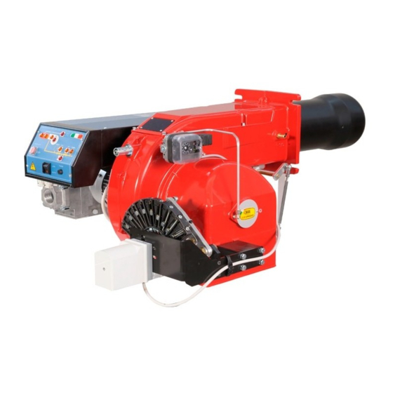
P60-P65
P72-P73A
Gas burners
MANUAL OF INSTALLATION - USE - MAINTENANCE
BURNERS - BRUCIATORI - BRULERS - BRENNER - QUEMADORES - ГОРЕЛКИ
M03956CR 12/2009
Table of
Contents
Previous
Page
Next
Page
1
2
3
4
5
Advertisement
Table of Contents
Need help?
Do you have a question about the P60 Series and is the answer not in the manual?
Ask a question
Questions and answers
Related Manuals for Unigas P60 Series
Indoor Fireplace Unigas P60 M-0.40 Series Installation, Operation And Maintenance Manual
(44 pages)
Burner Unigas P61 Manual Of Installation - Use - Maintenance
Gas burners (61 pages)
Indoor Fireplace Unigas P20 Installation, Operation And Maintanance Manual
Town gas version (52 pages)
Indoor Fireplace Unigas P73A Series Installation, Use And Maintenance Manual
(56 pages)
Indoor Fireplace Unigas IDEA Series Manual Of Installation - Use - Maintenance
(52 pages)
Indoor Fireplace Unigas LG35 Manual Of Installation - Use - Maintenance
(40 pages)
Indoor Fireplace Unigas TP90A Installation, User's, And Maintenance Manual
(56 pages)
Indoor Fireplace Unigas Idea Series Technical Manual Of Installation, Use And Maintenance
Gas burners (44 pages)
Indoor Fireplace Unigas TP1030 Manual
(60 pages)
Indoor Fireplace Unigas IDEA Series Manual Of Installation - Use - Maintenance
(89 pages)
Indoor Fireplace Unigas K590X Manual Of Installation - Use - Maintenance
(120 pages)
Indoor Fireplace Unigas HRX92R MG Series Manual Of Installation - Use - Maintenance
Lmv5x microprocessor-controlled gas - light oil burners (140 pages)
Indoor Fireplace Unigas K590X-FGR EA Manual Of Installation - Use - Maintenance
(49 pages)
Indoor Fireplace Unigas KPBY70 Manual Of Installation - Use - Maintenance
Lmv2x microprocessor-controlled gas - heavy oil burners (193 pages)
Indoor Fireplace Unigas RX92R M Series Manual
Lmv5x microprocessor controlled gas burners (123 pages)
Indoor Fireplace Unigas G225X Manual Of Installation - Use - Maintenance
Microprocessor controlled lmv 2x/3x gas burners (112 pages)
This manual is also suitable for:
P65 series
P73a series
P72 series
Table of Contents
Save PDF
Print
Rename the bookmark
Delete bookmark?
Delete from my manuals?
Login
Sign In
OR
Sign in with Facebook
Sign in with Google
Upload manual
Upload from disk
Upload from URL


Need help?
Do you have a question about the P60 Series and is the answer not in the manual?
Questions and answers