Table of Contents
Advertisement
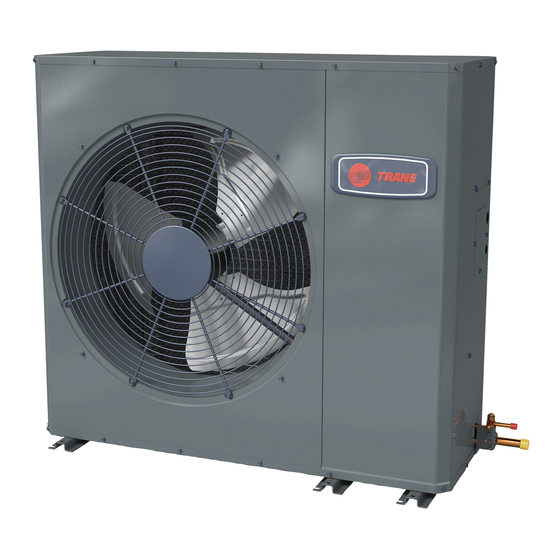
Installer's Guide
Variable Speed ComfortLink™ II
Side Discharge HP Models
For coastal applications where units are installed within one (1) mile of salt water, epoxy coated models are recommended.
These models have an 8 week lead time after order.
4TWL9024A1000A
4TWL9036A1000A
4TWL9048A1000A
4TWL9060A1000A
Only qualified personnel should install and service the equipment. The installation, starting up, and servicing of heating, ventilating,
and air-conditioning equipment can be hazardous and requires specific knowledge and training. Improperly installed, adjusted or
altered equipment by an unqualified person could result in death or serious injury. When working on the equipment, observe all pre-
cautions in the literature and on the tags, stickers, and labels that are attached to the equipment.
March 2020
Epoxy Coated Model
4TWL9024A1COTA
4TWL9036A1COTA
4TWL9048A1COTA
4TWL9060A1COTA
SAFETY WARNING
18-BC100D1-1C-EN
Note: "Graphics in this document are for representation only.
Actual model may differ in appearance."
Advertisement
Table of Contents


Need help?
Do you have a question about the Variable Speed ComfortLink II and is the answer not in the manual?
Questions and answers