Table of Contents
Advertisement
Installation, Operation, and Maintenance
VariTrane™ Variable Air Volume
(VAV) Terminal Air Units
Shutoff, Fan Powered, and CoolSense™
Sensible Cooling
Single-Duct: VCCF, VCEF, VCWF
Dual-Duct: VDDF
Fan-Powered: VPCF, VPEF, VPWF, VSCG, VSEG, VSWG
Fan-Powered Low Height: LPCF, LPEF, LPWF, LSCF, LSEF, LSWF
Chilled Water Sensible Cooling Terminal Units: LDCF, LDEF, LDWF, VDCF, VDEF, VDWF
Only qualified personnel should install and service the equipment. The installation, starting up, and servicing of heating, ventilating, and air-conditioning equipment
can be hazardous and requires specific knowledge and training. Improperly installed, adjusted or altered equipment by an unqualified person could result in death or
serious injury. When working on the equipment, observe all precautions in the literature and on the tags, stickers, and labels that are attached to the equipment.
September 2024
SAFETY WARNING
VAV-SVX08AA-EN
Advertisement
Table of Contents

Related Manuals for Trane VariTrane VCCF


Summary of Contents for Trane VariTrane VCCF
- Page 1 Installation, Operation, and Maintenance VariTrane™ Variable Air Volume (VAV) Terminal Air Units Shutoff, Fan Powered, and CoolSense™ Sensible Cooling Single-Duct: VCCF, VCEF, VCWF Dual-Duct: VDDF Fan-Powered: VPCF, VPEF, VPWF, VSCG, VSEG, VSWG Fan-Powered Low Height: LPCF, LPEF, LPWF, LSCF, LSEF, LSWF Chilled Water Sensible Cooling Terminal Units: LDCF, LDEF, LDWF, VDCF, VDEF, VDWF SAFETY WARNING Only qualified personnel should install and service the equipment.
-
Page 2: Warnings, Cautions, And Notices
(HCFCs). Not all refrigerants containing these compounds bump cap, fall protection, electrical PPE and arc have the same potential impact to the environment. Trane flash clothing). ALWAYS refer to appropriate advocates the responsible handling of all refrigerants. -
Page 3: Revision History
This document and the information in it are the property of Environmental, Health and Safety (EHS) policies Trane, and may not be used or reproduced in whole or in when performing work such as hot work, part without written permission. Trane reserves the right to... -
Page 4: Table Of Contents
Table of Contents General Information ......5 Duct Connections......39 Receiving and Handling . -
Page 5: General Information
These units are shipped completely assembled with the the bill of lading to insure all equipment and accessories exceptions of outlet duct temperature sensors on non- have been received. Contact your local Trane sales VCEF products, water valves, and accessories. Upon representative and notify the trucking company receiving the equipment, complete the following: immediately of any short ship or damaged equipment. -
Page 6: Model Numbers
N.O. 2-position) FM00 = Other Actuator and Control Digit 7, 8, 9— Not Used DD65 = UC400 Basic (Electric Heat Modulating FM01 = Trane Supplied Actuator, Other Control SCR) N.C. = Normally-Closed 000 = N/A DD66 = UC400 Basic plus- Local (Electric heat- N.O. - Page 7 Model Numbers Digit 12, 13, 14, 15 — Controls (continued) Digit 12, 13, 14, 15 — Controls (continued) Digit 12, 13, 14, 15 — Controls (continued) SE57 = Symbio™ 500 DDC- Basic plus Local SE87 = Symbio™ 210e DDC- Basic plus Local SY88 = Symbio™...
- Page 8 P = 3-Way Belimo Valve Piping Package, Analog C = Belimo™ Actuator Actuator Digit 24 — Disconnect Switch G = Trane Analog Actuator (Symbio™ 210/210e, Q = 2-Way Standard Valve Factory Mounted Piping Symbio™ 500, UC210, UC400) Package, Floating Point Actuator...
- Page 9 Model Numbers Digit 40 — Flow Rate 0 = None A = 0.5 gpm, 0.03 l/s B = 1.0 gpm, 0.06 l/s C = 1.5 gpm, 0.09 l/s D = 2.0 gpm, 0.13 l/s E = 2.5 gpm, 0.16 l/s F = 3.0 gpm, 019 l/s G = 3.5 gpm, 0.22 l/s H = 4.0 gpm, 0.25 l/s...
-
Page 10: Dual-Duct Vav Units
0 = Standard Digit 12, 13, 14, 15 — Controls A = Belimo™ Actuator 0 = None B = Trane Analog Actuator (Symbio™ 500, UC400) DD00 = Trane Actuator Only W = With Toggle DD41 = UC400 DDC Basic Variable Air Volume Digit 35 —... -
Page 11: Fan Powered Vav Units
ENCL = Shaft Only In Enclosure DD92 = UC210 DDC-Basic Plus Local (Electric SE75 = Symbio 210e DDC-Basic (Electric heat- DD00 = Trane Actuators Only heat-staged) Remote (Staged) PWM) DD41 = UC400 DDC-Basic (Cooling only) DD95 = UC210 DDC-Control with Modulating SCR SE77 = Symbio 210e DDC-Basic (Water heat-N.O. - Page 12 Digit 24 — Toggle Switch FM00 = Other Actuator and Control Digit 30 — Electric Heater Stage FM01 = Trane Supplied Actuator, Other Control 0 = With Toggle Switch VSCG and VSWG Digit 16 — Insulation W = Unit Disconnect with Toggle Switch VSEG...
- Page 13 B = Spring Return Actuator - Normally Open F = HW Valve, 4.7 Cv C = Spring Return Actuator - Normally Closed G = Trane Analog Actuator - Trane Conrols Only Digit 40 — Hot Water Flow Rate S = Special Actuator 0 = None (No Flow Rate) Digit 35 —...
-
Page 14: Series (Lsxf)
FM00 = Other Actuator and Control DD45 = UC400 DDC - Basic (Electric heat - PWM) (Water heat - N.O. 2-position) Remote (Water - FM01 = Trane Supplied Actuator, Other Control DD47 = UC400 DDC - Basic (Water heat - N.O. Modulating) SE41 = Symbio™... - Page 15 C = Spring return, Normally Closed Digit 25 — Power Fuse SY95 = Symbio 210 DDC - Control with Modulating G = Trane Analog Actuator (UC210 or UC400 only) 0 = None SY96 = Symbio 210 DDC - Space Temp Control Digit 35 —...
- Page 16 P = 3-Way Belimo Valve Piping Package, Analog Actuator Digit 39 — Water Valve 0 = None 1 = Trane HW Valve 0.7 Cv 2 = Trane HW Valve 2.7 Cv 5 = Analog HW Valve, Field Provided (UC210 or UC400 only) 6 = Trane HW Valve 1.7 Cv...
-
Page 17: Fan Powered Vav Units - Parallel
FM00 = Other Actuator and Control Digit 3— Reheat Modulating) Remote (Water- N.C. 2-position) FM01 = Trane Supplied Actuator, Other Ctrl DD60 = UC400 DDC- Basic Plus Local (Water SE41 = Symbio™ 500 DDC-Basic (Cooling only) or C = Cooling Only Heat- N.O. - Page 18 Model Numbers Digit 12, 13, 14, 15 — Controls (continued) Digit 12, 13, 14, 15 — Controls (continued) Digit 18 — Motor Voltage SE71 = Symbio 210e DDC - Basic (Cooling only) SY73 = Symbio 210 DDC - Basic (Water heat- 1 = 115/60/1 Modulating) SE72 = Symbio 210e DDC - Basic (Water heat- N.
- Page 19 Digit 39 — Water Valve A = Belimo™ Actuator Digit 27, 28, 29 — Electric Heat kW G = Trane Analog Actuator (Trane Controls only) 0 = None Digit 35 — Wireless Sensors 1 = Trane HW Valve 0.7 Cv 000 = None 2 = Trane HW Valve 2.7 Cv...
-
Page 20: Fan Powered Low Height Vav Units
Modulating) Remote (Water- N.O. 2-position) FM00 = Other Actuator and Control DD59 =UC400 DDC- Basic plus Local (Water heat- FM01 = Trane Supplied Actuator, Other Ctrl Modulating) Remote (Water- N.C. 2-position) 00 = N/A SE41 = Symbio™ 500 DDC-Basic (Cooling only) or... - Page 21 Model Numbers Digit 12, 13, 14, 15 — Controls (continued) Digit 12, 13, 14, 15 — Controls (continued) Digit 18 — Motor Voltage SE71 = Symbio 210e DDC - Basic (Cooling only) SY73 = Symbio 210 DDC - Basic (Water heat- 1 = 115/60/1 Modulating) SE72 = Symbio 210e DDC - Basic (Water heat- N.
- Page 22 J = 380/50/3 A = Belimo™ Actuator Digit 39 — Water Valve Digit 27, 28, 29 — Electric Heat kW G = Trane Analog Actuator (Trane Controls only) Digit 35 — Wireless Sensors 0 = None 000 = None 1 = Trane HW Valve 0.7 Cv 010 = 1.0 kW...
-
Page 23: Units
Digit 22 — Hot Water Coil Connection FM00 = OTHER Actuator and Control VDEG = Series DOAS Fan Powered - With Electric FM01 = Trane Supplied Actuator, Other Control Heat 1 = Same Side Connection - Coil and Control VDWG = Series DOAS Fan Powered - With Hot Digit 16 —... - Page 24 5 = Analog HW Valve, Field Provided H = 3 Way Belimo Valve Only, Floating Point 6 = HW Valve, 1.7 Cv G = Trane Analog Actuator - Trane Conrols Only Actuator 7 = HW Valve, 5.0 Cv S = Special Actuator J = 2 Way Belimo Valve Piping Package, Floating A = HW Valve, 0.3 Cv, Belimo...
- Page 25 Model Numbers Digit 44 — Chilled Water Valve 0 = None (No Water Valve) 1 = CW VALVE 0.7 Cv 2 = CW VALVE 2.7 Cv 5 = Analog CW Valve, Field Provided 6 = CW Valve 1.7 Cv 7 = CW Valve 5.0 Cv A = CW Valve 0.3 Cv B = CW Valve 0.46 Cv C = CW Valve 0.8 Cv...
-
Page 26: Unit Information
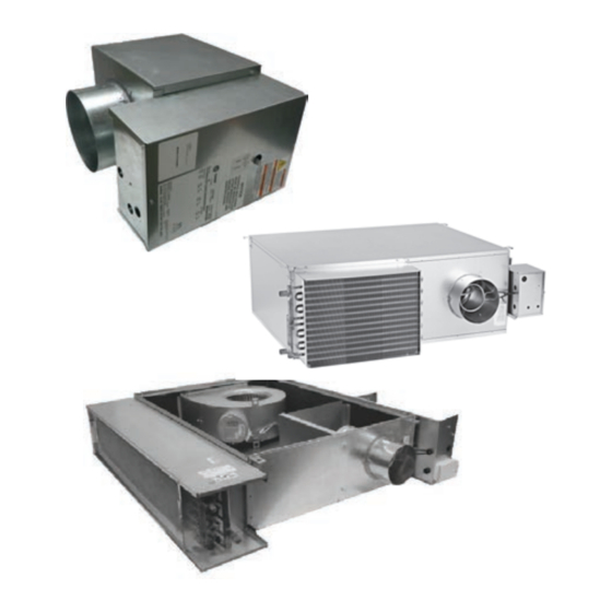
Unit Information Single-Duct VAV Units Typical Single-Duct VAV Units Figure 1. Typical single-duct unit; VCCF VCWF, VCEF The basic unit consists of a sheet metal casing with an air valve, which is used to modulate the air being delivered into the occupied zone. The unit is designed to modulate either cooling or heating air between 40°F and 140°F (4.44°C and 60°C). -
Page 27: Single Duct Hot Water Vav With Factory Installed Piping Package
The typical result is that the air flowing into the zone stays at a constant flow whether the unit is heating or cooling. Factory-installed Trane unit controls available include; • Symbio™ 500 or UC400 — one required per unit Figure 3. -
Page 28: Fan-Powered/Fan-Powered Low Height
Unit Information Fan-Powered/Fan-Powered Low not maintain the desired temperature, reheat will be activated to increase the temperature of the discharge air. Height VAV Units On a parallel unit, the VariTrane™ air valve delivers VariTrane™ fan-powered and low height fan-powered units primary cooling air to the unit outlet. - Page 29 The function of the Trane chilled water sensible cooling it, to detect and prevent any moisture from getting on the terminal units is a little different than traditional VAV ceiling beneath the units or into the occupied space below.
-
Page 30: Unit Installation
RH or LH connection orientation if model number or other energy storing components provided by digit 22 Electrical Connections = F. Trane or others, refer to the appropriate manufacturer’s literature for allowable waiting periods Single Duct Hot Water VAV with for discharge of capacitors. -
Page 31: Installation
Unit Installation Installation limited to the range of 32°F to 225°F. 3. Piping packages are fully compatible with ethylene 1. Determine which is the supply section and which is the glycol and propylene glycol with all concentrations. return section. The strainer is only on the supply side. Flow controls and the proportional water valve are only Maintenance on the return side. -
Page 32: Manual Operation
Discharge Airflow Table 1. Dual-duct VAV unit hanger location dimensions Do NOT rotate the lever before pressing Inlet the button. Size (in) Figure 13. Trane water valve 5–10 23.15 25.25 1.38 Rotate the lever (or use 8mm Allen key) 12–16 23.15 37.25... -
Page 33: Fan-Powered Vav Units And Chilled Water Sensible Cooling Terminal Units
Unit Installation Fan-Powered VAV Units and either hanger straps or by using a threaded rod in conjunction with the hanger brackets that are provided on Chilled Water Sensible Cooling the unit. Care should be exercised to insure that the Terminal Units hanging straps do not block the side access panel. - Page 34 Unit Installation Figure 16. TOP VIEW 1.38 1.38 1.38 1.38 Primary Primary Airflow 1.50 Airflow 1.50 1.60 1.50 1.50 1.60 1.50 1.50 36.75 36.75 1.65 1.50 1.50 Water Coil 1.50 1.65 1.65 Electric Heater 23.15 1.65 Airflow Discharge Outlet Airflow Discharge Outlet DISCHARGE VIEW Table 3.
- Page 35 Unit Installation Figure 17. TOP VIEW 1.38 1.38 1.38 1.38 1.50 Primary Primary 1.50 1.50 1.50 Airflow Airflow 38.35 38.35 1.50 1.65 Water Coil 1.50 1.50 1.50 1.65 Electric Heater 1.65 1.65 23.15 Airflow Discharge Outlet Airflow Discharge Outlet DISCHARGE VIEW Table 4.
- Page 36 Unit Installation Figure 18. Low height parallel DS02/PS02 39.1 39.1 [993] [993] Primary Airflow Primary Airflow Airflow Plenum Airflow Plenum Inlet Inlet 34.3 34.3 [871] [871] 34.3 [871] 34.3 [871] Water Coil Airflow Discharge Outlet Airflow Discharge Outlet 39.1 [993] 39.1 [993] 39.1...
- Page 37 Unit Installation Figure 19. Low height series DS02/PS02/DS03 w/hot water or electric heat 32.3 [821] 32.3 Primary Airflow [821] Primary Airflow Airflow Plenum Inlet Airflow Plenum Inlet 41.2 [1047] 41.2 [1047] 61.2 [1555] Water Coil Airflow Optional Electric Discharge Outlet Heater Airflow Discharge [51]...
-
Page 38: Bracket Locations
Unit Installation Bracket Locations Bracket Locations VDxG Figure 20. Bracket locations VDxG TOP VIEW 1.38 1.50 1.38 1.50 Primary Primary Airflow Airflow 1.60 1.60 36.75 36.75 Water Coil 23.15 Electric Heater Airflow Discharge Outlet Airflow Discharge Outlet DISCHARGE VIEW Table 5. Hanger bracket location dimensions - VDxG (Electric heater only) Fan Size Small... -
Page 39: Duct Connections
Unit Installation Duct Connections Chilled Water Sensible Cooling Terminal Units All VariTrane™ units should be provided with a minimum of 1.5-duct diameters of straight duct prior to the inlet of the Figure 21. Bracket locations — cooling only unit, and unit. -
Page 40: Electrical Installation
Unit Installation Discharge Duct Temperature • Water inlet is always on the airflow downstream side of the hot water coil. Sensor Installation • Water outlet is always on the upstream side of the Note: This process is to be used for control sequences hot water coil. -
Page 41: Chilled Water Sensible Cooling Terminal Units Moisture Sensor Installation
Unit Installation Notes: dedicated outdoor-air unit. Trane chilled water sensible cooling terminal units are built with a drip pan located • Cut loose harness, verify location. beneath and above the cooling coil, with a moisture sensor • Avoid location where excessive vibration,... -
Page 42: Stand-Alone Symbio™ 500 And Uc400
< supply air temperature < zone temperature unit malfunction. +10°F] (5.5°C), the control action remains the same and Trane offers a factory-mounted actuator with a 90-second the Symbio 210, Symbio 210e, or UC210 controls to the drive time. The actuator drives 1° per second. A field- minimum flow set point. -
Page 43: Base Unit Weights
Unit Installation Base Unit Weights Note: Refer to unit submittal for as-built unit weight. Table 6. Single-duct units — lb/kg Single Wall Insulation Dual Wall Insulation Unit Size VCWF VCWF VCCF VCEF VCCF VCEF 1–Row 2–Row 3–Row 4–Row 1–Row 2–Row 3–Row 4–Row 16/7... - Page 44 Unit Installation Table 8. Parallel fan-powered units — lb/kg Single Wall Dual Wall VPxF Unit Size VPWF VPWF Suppressor VPCF VPEF VPCF VPEF 1–Row 2–Row 1–Row 2–Row 0502SQ 81/37 110/550 92/42 95/43 115/52 144/65 126/57 129/59 15.5/7.0 0602SQ 80/36 109/49 91/41 94/43 114/52...
- Page 45 Unit Installation Table 9. Series fan–powered units — lb/kg Single Wall VSWG Unit Size VSCG VSEG 1 Row 2 Row 3 Row 4 Row Small 28.6 44.5 34.5 36.3 37.6 Small Aten 38.6 54.4 44.5 46.3 47.6 Medium 46.3 64.4 53.1 55.3 57.2...
- Page 46 Unit Installation Table 11. Low height series units — lb/kg Single Wall Dual Wall LSxF Unit Size LSWF LSWF Attenuator LSCF LSEF LSCF LSEF 1–Row 2–Row 1–Row 2–Row 04DS02 89/41 107/49 95/43 97/44 112/51 130/59 118/54 120/55 14/6 04PS02 91/42 108/49 97/44 99/45...
-
Page 47: Unit Setup
Unit Setup Figure 26. Flow sensor ΔP vs. airflow delivery 8" x 12" 6” 8" 14" 16" 10" 12" 16" x 24" 4” 5” 0.01 1,000 10,000 Airflow (CFM) Fan Motor Amperage Reference unit submittal data and motor nameplate. Adjusting the SCR Motor Speed Control In order to make units more convenient and efficient to balance, an SCR (silicone control rectifier) is provided as... -
Page 48: Electrically Commutated Motor (Ecm)
210/210e, Symbio™ 500, Tracer® UC210 and UC400) or shunt placement non-Trane unit controller Trane offers an energy efficient ECM as a motor option. The optional Symbio™ 210/210e, Symbio™ 500, Tracer® UC210 and UC400 unit controllers directly interface with The ECM control interface contains two diagnostic LED the ECM to control fan airflow and fan on/off control. - Page 49 100% 10.0 10.0 % setting from Trane unit controller via pulse width modulating signal or ECM control board with manual fan speed adjust setting. ECM control board with 0-10 VDC fan modulation input and separate fan on/ off binary input required.
- Page 50 2100 100% 10.0 10.0 % setting from Trane unit controller via pulse width modulating signal or ECM 1301 control board with manual fan speed adjust setting. 1379 ECM control board with 0-10 VDC fan modulation input and separate fan on/ off binary input required.
- Page 51 100% 10.0 10.0 1010 % setting from Trane unit controller via pulse width modulating signal or ECM 1071 control board with manual fan speed adjust setting. ECM control board with 0-10 VDC fan modulation input and separate fan on/ 1133 off binary input required.
- Page 52 LSxF, LPxF, LDxF DS02 ECM CFM (continued) Airflow Trane Controller ECM Control Board % setting from Trane unit controller via pulse width modulating signal or ECM (Min CFM: 700, Max control board with manual fan speed adjust setting. PWM Signal Signal...
- Page 53 1960 2350 Notes: 1075 1278 % setting from Trane unit controller via pulse width modulating signal or ECM control board with manual fan speed adjust setting. 1155 1375 ECM control board with 0-10 VDC fan modulation input and separate fan...
-
Page 54: Wiring Diagrams
Wiring Diagrams Notes: See programming guides listed below for detailed • Symbio™ 210 BAS-SVX084*-EN class II low voltage unit controls wiring information • Symbio™ 500 BAS-SVX091*-EN on the following: • UC400: VAV-SVX07*-EN • UC210: BAS-SVX62*-EN VAV-SVX08AA-EN... -
Page 55: Wiring - Electric Heater Control Box
DASHED LINE ENCLOSURES AND/OR DASHED DEVICE OUTLINES HIGH TEMPERATURE CUTOUT (MANUAL RESET) INDICATE COMPONENTS THAT ARE OPTIONAL OR GROUPED TOGETHER. SOLID LINES INDICATE WIRING BY TRANE. HIGH TEMPERATURE CUTOUT (AUTO RESET) SUPPLY AIR PROVING SWITCH ALL FIELD WIRING MUST BE IN ACCORDANCE WITH THE CONTROL POWER TRANSFORMER NATIONAL ELECTRIC CODE (NEC), STATE AND LOCAL REQUIREMENTS. - Page 56 DASHED LINE ENCLOSURES AND/OR DASHED DEVICE OUTLINES HIGH TEMPERATURE CUTOUT (MANUAL RESET) INDICATE COMPONENTS THAT ARE OPTIONAL OR GROUPED TOGETHER. SOLID LINES INDICATE WIRING BY TRANE. HIGH TEMPERATURE CUTOUT (AUTO RESET) SUPPLY AIR PROVING SWITCH ALL FIELD WIRING MUST BE IN ACCORDANCE WITH THE CONTROL POWER TRANSFORMER NATIONAL ELECTRIC CODE (NEC), STATE AND LOCAL REQUIREMENTS.
- Page 57 DASHED LINES INDICATE RECOMMENDED FIELD WIRING BY OTHERS. DASHED LINE ENCLOSURES AND/OR DASHED DEVICE OUTLINES INDICATE COMPONENTS THAT ARE OPTIONAL OR GROUPED TOGETHER. SOLID LINES INDICATE WIRING BY TRANE. ALL FIELD WIRING MUST BE IN ACCORDANCE WITH THE NATIONAL ELECTRIC CODE (NEC), STATE AND LOCAL REQUIREMENTS.
- Page 58 HIGH TEMPERATURE CUTOUT (MANUAL RESET) INDICATE COMPONENTS THAT ARE OPTIONAL OR GROUPED HIGH TEMPERATURE CUTOUT (AUTO RESET) TOGETHER. SOLID LINES INDICATE WIRING BY TRANE. SUPPLY AIR PROVING SWITCH CONTROL POWER TRANSFORMER ALL FIELD WIRING MUST BE IN ACCORDANCE WITH THE NATIONAL ELECTRIC CODE (NEC), STATE AND LOCAL REQUIREMENTS.
- Page 59 SINGLE PHASE INDICATE COMPONENTS THAT ARE OPTIONAL OR GROUPED HIGH TEMPERATURE CUTOUT (AUTO RESET) LINE VOLTAGES TOGETHER. SOLID LINES INDICATE WIRING BY TRANE. SUPPLY AIR PROVING SWITCH CONTROL POWER TRANSFORMER ALL FIELD WIRING MUST BE IN ACCORDANCE WITH THE NATIONAL ELECTRIC CODE (NEC), STATE AND LOCAL REQUIREMENTS.
- Page 60 HIGH TEMPERATURE CUTOUT (MANUAL RESET) INDICATE COMPONENTS THAT ARE OPTIONAL OR GROUPED HIGH TEMPERATURE CUTOUT (AUTO RESET) TOGETHER. SOLID LINES INDICATE WIRING BY TRANE. SUPPLY AIR PROVING SWITCH CONTROL POWER TRANSFORMER ALL FIELD WIRING MUST BE IN ACCORDANCE WITH THE NATIONAL ELECTRIC CODE (NEC), STATE AND LOCAL REQUIREMENTS.
- Page 61 Wiring Diagrams Figure 37. Single-duct, single phase, 1 leg VAV-SVX08AA-EN...
- Page 62 DASHED LINE ENCLOSURES AND/OR DASHED DEVICE OUTLINES INDICATE COMPONENTS THAT ARE OPTIONAL OR GROUPED HIGH TEMPERATURE CUTOUT (MANUAL RESET) TOGETHER. SOLID LINES INDICATE WIRING BY TRANE. HIGH TEMPERATURE CUTOUT (AUTO RESET) FAN PROVING SWITCH ALL FIELD WIRING MUST BE IN ACCORDANCE WITH THE CONTROL POWER TRANSFORMER NATIONAL ELECTRIC CODE (NEC), STATE AND LOCAL REQUIREMENTS.
- Page 63 DASHED LINE ENCLOSURES AND/OR DASHED DEVICE OUTLINES SINGLE PHASE INDICATE COMPONENTS THAT ARE OPTIONAL OR GROUPED STAGES TOGETHER. SOLID LINES INDICATE WIRING BY TRANE. LINE VOLTAGES ALL FIELD WIRING MUST BE IN ACCORDANCE WITH THE NATIONAL ELECTRIC CODE (NEC), STATE AND LOCAL REQUIREMENTS.
- Page 64 LINE VOLTAGES DASHED LINE ENCLOSURES AND/OR DASHED DEVICE OUTLINES INDICATE COMPONENTS THAT ARE OPTIONAL OR GROUPED TOGETHER. SOLID LINES INDICATE WIRING BY TRANE. ALL FIELD WIRING MUST BE IN ACCORDANCE WITH THE NATIONAL ELECTRIC CODE (NEC), STATE AND LOCAL REQUIREMENTS.
-
Page 65: Control Box Wiring
Wiring Diagrams Control Box Wiring Figure 41. Single-duct control box VAV-SVX08AA-EN... - Page 66 Wiring Diagrams Figure 42. Fan-powered units with PSC motors VAV-SVX08AA-EN...
- Page 67 Wiring Diagrams Figure 43. Fan-powered units with ECM motor VAV-SVX08AA-EN...
- Page 68 Wiring Diagrams Figure 44. Fan-powered units with ECV motor VAV-SVX08AA-EN...
-
Page 69: Maintenance
For three phase applications, or other energy storing components provided by a Manager-Subordinate configuration is used to switch two Trane or others, refer to the appropriate legs of three phase power to the heater stage. The manufacturer’s literature for allowable waiting periods Manager Relay controls one leg independently, and for discharge of capacitors. - Page 70 Maintenance Figure 46. Typical heat sink fin orientation unit must be mounted with a minimum of 1 inch clearance in front of the slots. When the 0-10 VDC control voltage is present at the Manager relay in both single and three phase applications, an ON indicating LED light on the Manager relay will blink continually (approximately 0.5 seconds on, 1.0 seconds off).
- Page 71 Notes VAV-SVX08AA-EN...
- Page 72 For more information, please visit trane.com or tranetechnologies.com. Trane has a policy of continuous product and product data improvements and reserves the right to change design and specifications without notice. We are committed to using environmentally conscious print practices.
Need help?
Do you have a question about the VariTrane VCCF and is the answer not in the manual?
Questions and answers