Table of Contents
Advertisement
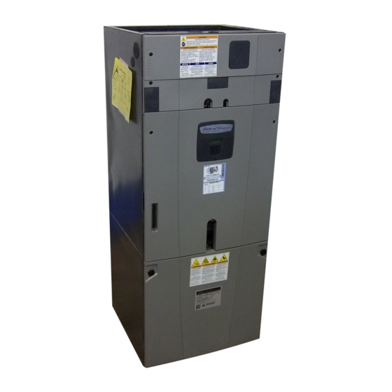
Hyperion Field Reference Data TAM8
Air Handler - Convertible
Models: Series 8 Air Handlers 2-5 Ton
*AM8A0A24V21CA, *AM8A0B30V21CA
*AM8A0C36V31CA, *AM8A0C42V31CA
*AM8A0C48V41CA, *AM8A0C60V51CA
* May be "A" or "T"
For use with BAYEV or BAYW series heaters ONLY
WARNING:
IMPORTANT --- This document contains a wiring diagram and service information. This is customer property and is to remain with this unit.
Please return to service information pack upon completion of work.
▲
!
SAFETY HAZARD!
This information is intended for use
by individuals possessing adequate backgrounds of electrical and
mechanical experience. Any attempt to repair a central air condition-
ing product may result in personal injury and/or property damage.
The manufacture or seller cannot be responsible for the interpreta-
tion of this information, nor can it assume any liability in connection
with its use.
!
▲
LIVE ELECTRICAL COMPONENTS!
lation, testing, servicing, and troubleshooting of this product, it may
be necessary to work with live electrical components. Failure to fol-
low all electrical safety precautions when exposed to live electrical
components could result in death or serious injury.
NOTE: This unit as shipped is ONLY compatible with
Trane and American Standard communicating thermostats
and outdoor units. (24VAC thermostats cannot be used)
With the addition of a BAYCC24VK01 accessory, this unit
can be compatible with a 24VAC single or multistage heat
pump or air conditioner.
Table of Contents
Product Specifications. .................................................................................................... 2
Wiring Diagram. ............................................................................................................... 3
Sequence of Operation. ................................................................................................... 4
Control Layout - Refrigerant Dip Switch .......................................................................... 6
Airflow Performance. ........................................................................................................ 7
Heater Attribute Data. .................................................................................................... 13
Control Layout - LEDs. ................................................................................................... 16
Alert Codes. ................................................................................................................... 22
EEV Test Procedures. .................................................................................................... 23
EVC Thermal Resistance and Voltage Table. ................................................................ 24
AFC Supply Air Temperature Sensor Table. ................................................................... 25
Display Assembly Menus. .............................................................................................. 26
Troubleshooting. ............................................................................................................ 32
NOTICE: Since the manufacturer has a policy of continuous product and product data improvement, it reserves the right to change design and specifications without notice.
© 2011 Trane
HAZARDOUS VOLTAGE - DISCONNECT POWER BEFORE SERVICING
WARNING
WARNING
During instal-
!
▲
PRESSURIZED REFRIGERANT!
OIL AND REFRIGERANT UNDER HIGH PRESSURE. RECOVER
REFRIGERANT TO RELIEVE PRESSURE BEFORE OPENING THE
SYSTEM.
DO NOT USE NON-APPROVED REFRIGERANTS OR REFRIGERANT
SUBSTITUTES OR REFRIGERANT ADDITIVES.
Note: This unit is certified to UL 1995.
The interior cabinet wall meets the following:
- UL94-5VA Flame Class Listed
- UL723 Steiner Tunnel Listed for 25/50 Flame/
Smoke
- UL746C Listed for Exposure to Ultraviolet Light,
Water Exposure and Immersion
WARNING
SYSTEM CONTAINS
Advertisement
Table of Contents

Related Manuals for Trane Hyperion AM8A0A24V21CA Series


Summary of Contents for Trane Hyperion AM8A0A24V21CA Series
-
Page 1: Table Of Contents
Water Exposure and Immersion NOTE: This unit as shipped is ONLY compatible with Trane and American Standard communicating thermostats and outdoor units. (24VAC thermostats cannot be used) With the addition of a BAYCC24VK01 accessory, this unit can be compatible with a 24VAC single or multistage heat pump or air conditioner. -
Page 2: Product Specifications
PRODUCT SPECIFICATIONS *AM8A0A24V21CA *AM8A0B30V21CA MODEL *AM8A0C36V31CA RATED VOLTS/PH/HZ. 200-230/1/60 200-230/1/60 200-230/1/60 See O.D. Specifications See O.D. Specifications See O.D. Specifications RATINGS 1 Plate Fin Plate Fin INDOOR COIL — Type Plate Fin 3 - 14 Rows — F.P.I. 3 - 14 3 - 14 3.67 5.04... -
Page 3: Wiring Diagram
TAM83... -
Page 4: Sequence Of Operation
• HHC= Hydronic Heat Control 5. When a request for cooling is removed, the AFC will turn off the blower motor after any user selected This unit as shipped is ONLY compatible with Trane fan-off delays have expired. and American Standard communicating thermo- NOTE: Delay profiles from the thermostat may change stats and OD units. - Page 5 NOTE: The EHC has “lead-lag or rotating” logic built in Important: The switch action must be selected in the that energizes the electric heat relays based upon Configuration Menu section of the Display Assem- cycle counts. To verify operation of all heating bly to either “Disable Cool”...
-
Page 6: Control Layout - Refrigerant Dip Switch
Fault Reporting Control boards in this unit store active and historical faults. Each control board will report active faults continuously and will report the last four faults stored after a power cycle of the unit. See Fault Table section for list of fault codes The active and historical faults can also be accessed through the Alert Menu in the Display Assembly. -
Page 7: Airflow Performance
TAM87... - Page 8 TAM88...
- Page 9 TAM89...
- Page 10 TAM810...
- Page 11 TAM811...
- Page 12 TAM812...
-
Page 13: Heater Attribute Data
AM8 HEATER ATTRIBUTE DATA Heater Attribute Data *AM8A0A24V21SA 240 Volt 208 Volt No. of Capacity Heater Minimum Maximum Capacity Heater Minimum Maximum Heater Model No. Circuits Amps per Circuit Overload Amps per Circuit Overload Circuit Ampacity Protection Circuit Ampacity Protection BTUH BTUH No Heater... - Page 14 AM8 HEATER ATTRIBUTE DATA Heater Attribute Data *AM8A0C42V31SA 240 Volt 208 Volt No. of Capacity Heater Minimum Maximum Capacity Heater Minimum Maximum Heater Model No. Circuits Amps per Circuit Overload Amps per Circuit Overload Circuit Ampacity Protection Circuit Ampacity Protection BTUH BTUH No Heater...
- Page 15 SUBCOOLING ADJUSTMENT Indoor Unit Model No. Outdoor Unit Model No. Subcooling *AM8A0B30V21CA 4A6H6024E, 4TWX6024E 9° *AM8A0C36V31CA 4A6H6036E, 4TWX6036E 10° *AM8A0C48V41CA 4A6H6048E, 4TWX6048E 8° *AM8A0B30V21CA 4A7A6024E, 4TTX6024E 8° *AM8A0C36V31CA 4A7A6036E, 4TTX6036E 8° *AM8A0C48V41CA 4A7A6048E, 4TTX6048E 8° *AM8A0B30V21CA 4TWZ0024A, 4A6Z0024A 9° *AM8A0C36V31CA 4TWZ0036A, 4A6Z0036A 10°...
-
Page 16: Control Layout - Leds
Air Handler Control Panel - LEDs TAM816... - Page 17 AFC BM (Bit Master) LED (GREEN LED) WIRE AFC BM LED Description Solid ON Normal operation AFC COMM LED (AMBER LED) AFC COMM LED Description Device count Number of communicating devices* STATUS * Examples: communicating thermostat, communicating air cleaner, etc. BM LED UNIT COMM...
- Page 18 EVC STATUS CODES (GREEN LED) EVC STATUS LED (Non Heat Pump Systems) Flash STATUS Cool mode selected / No active call Active call for 1st stage cooling UNIT Active call for 2nd stage cooling STATUS UNIT FAULT FAULT NOTE: (1) Single stage OD systems will report 2nd stage flash codes EVC STATUS LED (Heat Pump Systems) R410A / R22 OPEN...
- Page 19 On a call for heat, STATUS LED will flash per the table above every 4 seconds EHC FAULT CODES (RED LED) EHC Fault Description No fault Internal communication error Heat relay stuck open Heat relay stuck closed Non‐cycling limit (NTCO) or element open Cycling limit (CTCO)open Configuration error Blower interlock relay stuck open or stuck closed NOTES: 1) Confirm heater model and kw jumper match UNIT STATUS TRANE U.S. INC. UNIT +13.8V STATUS FAULT FAULT TAM819...
- Page 20 Standby or idle (see note) 2 per second Heating demand is present HHC UNIT LED (BLUE LED) Unit LED Description 1 Flash Normal (1 flash every 4 seconds) Rapid Communication Busy Error (2 flashes per second) SOLID ON Communications cannot be established with the AFC No Power FAULT 13.8V DATA A DATA B STATUS FAULT MOV1 13.8VDC STATUS UNIT UNIT MCLR TRANE U.S. INC. TAM820...
- Page 21 1 Flash per 4 seconds 1st Stage 2 Flash per 4 seconds 2nd Stage CCM FAULT LED (RED LED) CCM FAULT LED Description 3 Flash Communication Error TRANE U.S. INC TRANE U.S. INC CR28 STATUS LED4 STATUS CR43 CR44 LED3...
-
Page 22: Alert Codes
ALERT CODES FOR *AM8 Alert Display Notification Alert Group A/TCONT900 A/TZONE 950 Alert Description Possible Cause Fault Fault Fault Fault Code Assembly Text Level Code Code Code Code Control failure CNTRL FLT ERR18 ERR 18.0 Critical Internal Control Error Control fault, replace AFC More than one ID unit connected on the Twinning fault TWIN ERR... -
Page 23: Eev Test Procedures
EEV TEST PROCEDURES Temperature Sensor (GT) Evaporator Temperature Sensor (ET) Note: Some future models may not have external check valve. Electronic Expansion Valve Test Option 1 Access the Unit Test option through Display Assembly under the Control Menu. Electronic Expansion Valve Test Option 2 Note: Close Valve and Open Valve Tests are active in any mode of operation Test Pins: OPEN, CLOSE, TEST (See J4 on EVC Board) Close Valve Test... -
Page 24: Evc Thermal Resistance And Voltage Table
EVC THERMAL RESISTANCE AND VOLTAGE TABLE Volts DC at plug J3 Volts DC at plug J3 TEMP TEMP TEMP TEMP THERMISTOR THERMISTOR EVAP TEMP (ET) - Orange to Orange EVAP TEMP (ET) - Orange to Orange RESISTANCE RESISTANCE GAS TEMP (GT) - Black to Black GAS TEMP (GT) - Black to Black (OHMS) (OHMS) -
Page 25: Afc Supply Air Temperature Sensor Table
AFC SUPPLY AIR TEMPERATURE SENSOR TABLE Thermistor Thermistor Temp. Temp. Volts DC Temp. Temp. Volts DC Resistance Resistance °F °C @ plug J10 °F °C @ plug J10 Ohms Ohms -17.8 83247 2.946 -17.2 80645 2.936 24.4 9990 1.649 Airflow Control (AFC) -16.7 78133 2.926... -
Page 26: Display Assembly Menus
Display Assembly Display Assembly Push up & down to scroll Viewing Window through setup menu Push center button Push left & right to scroll to make selection through menu options Display Assembly General Notes Display Assembly General Notes • Home Screen o The System Status is shown continuously on the Home Screen. - Page 27 Display Assembly Home Menu Home Screen Auto scroll SYSTEM STATUS UNIT DATA ↕ UNIT CONTROLS ↕ XXXXXXXXXXXXXX ↔ ↔ ↔ ALERT 1 <Cntrl> UNIT MODEL # ↕ AFC SW BUILD ↕ AFC SW VERSION <Alert short text> XXXXXXXXXXXXXXX XXXXXXXXXX ↔ XXXXXXXXXX ↔...
- Page 28 Monitor Menu Technician Monitor Menu • The Monitor menu allows the technician to monitor the different aspects of the system while the air handler is running. No changes can be made in the Monitor Menu. • Superheat is only shown in cooling and defrost modes •...
- Page 29 Alert Menu MONITOR CONFIG ALERT MENU ↕ menu menu ↔ ACTIVE ALERTS ↕ ALERT HISTORY ↕ ↔ ↔ BLW COMM ERR AF ↕ <Alert shrt text><Cntrl>↕ <Alert shrt text><Cntrl>↕ <Alert shrt text><Cntrl>↕ AH CB BI AH CH CC BI ## ↔ DDDD:HH:MM:SS ↔...
- Page 30 Config Menu ALERT CONTROL Note: CONFIG MENU ↕ menu menu “ “ denotes active value ↔ “*” indicates factory value AIRFLOW MODE ↔↕ AIRFLOW MODE ↔ TRQ* COOL CFM/TON ↔↕ XXX* COOL CFM/TON & HEAT CFM/TON OPTIONS: 290 – 450 CFM/TON HEAT CFM/TON ↔↕...
- Page 31 Control Menu CONFIG MONITOR CONTROL MENU ↕ menu ↔ menu EVC TEST ↔↕ EVC TEST ↔↕ OPEN CLOSE CONTROL CFM ↔↕ XXXX XXXX UNIT TEST ↕ TEST IN PROGRESS TEST IN PROGRESS TEST IN PROGRESS TEST COMPLETE START? YES <ENTER> EXPANSION VALVE BLOWER RUN AUXILIARY HEAT...
-
Page 32: Troubleshooting
Troubleshooting Verify connections for sensors are plugged in and connected properly Sensor Check Start Here Turn System switch on thermostat to Measure VDC at J3 connector on EVC. Wait 10 minutes Measure return air temperature OFF and Fan to ON position (See EVC table for J3 location) Does voltage(s) measured correspond Proceed to next... - Page 33 HIGH SUPERHEAT Superheat above 30F at OD unit Start Here Verify that OD Verify line set is Is subcooling at the Perform condenser coils properly sized for outdoor unit temperature are clean application between 8-12F? sensor check Add refrigerant until subcooling Is liquid line temperature Verify line set size reaches ~10F...
- Page 34 LOW SUPERHEAT Superheat below 3F at OD unit Start Here Insure ID motor is running Is filter, coil, Clean or replace and blower as needed wheel clean? Perform sensor check Perform “CLOSE VALVE” test at EVC. Perform “OPEN Does suction VALVE”...
- Page 35 TAM835...
- Page 36 05/11 Trane 6200 Troup Highway Tyler, TX 75707 www.trane.com The manufacturer has a policy of continuous product and product data improvement, and it reserves the right to change design and specifications without notice. For more information contact your local dealer (distributor)
Need help?
Do you have a question about the Hyperion AM8A0A24V21CA Series and is the answer not in the manual?
Questions and answers