
Related Manuals for Carrier Connect 33CONNECTSTAT43


Summary of Contents for Carrier Connect 33CONNECTSTAT43
- Page 1 Carrier Connect™ Wi-Fi Thermostat 33CONNECTSTAT43 Installation Guide ©2022 Carrier. All rights reserved. • Catalog No. 11-808-728-01 • 12/2/2022...
- Page 2 Verify that you have the most current version of this document from www.hvacpartners.com, the Carrier Partner Community website, or your local Carrier office. Important changes are listed in Document revision history at the end of this document. ©2022 Carrier. All rights reserved.
-
Page 3: Table Of Contents
Using the Connect website or app........................10 Configuring the system ............................13 To configure advanced SYSTEM SETTINGS ....................14 Operating your system using the Carrier® Connect™ Wi-Fi Thermostat ............22 Occupancy ................................22 Supply fan ................................22 Cooling ................................. 23 Econ enable ................................ - Page 4 Contents Appendix: BACnet Points List ..........................43 Document revision history..........................49...
-
Page 5: What Is The Carrier Connect™ Wi-Fi Thermostat
What is the Carrier Connect™ Wi-Fi Thermostat? The Carrier® Connect™ Wi-Fi Thermostat (Part #33CONNECTSTAT43) is a thermistor-based wireless thermostat that can sense a 10K Type II OAT or a remote space or return air sensor and can control up to 4 heating and 3 cooling stages. -
Page 6: Wiring The Carrier® Connect™ Wi-Fi Thermostat
Wiring the Carrier® Connect™ Wi-Fi Thermostat Wiring the Carrier® Connect™ Wi-Fi Thermostat To wire the thermostat to equipment Packaged Rooftop Units Hydronic Fan Coil 33CONNECTSTAT43 ©2022 Carrier. Installation Guide All rights reserved. - Page 7 Wiring the Carrier® Connect™ Wi-Fi Thermostat Dual fuel systems Furnace/AC System (Furnace and heat pumps) Water Source Heat Pump Air Handler or DX Fan Coil/AC Split System 33CONNECTSTAT43 ©2022 Carrier. Installation Guide All rights reserved.
-
Page 8: To Wire And Mount The Thermostat
Wiring the Carrier® Connect™ Wi-Fi Thermostat Air Handler or DX Coil/Heat Pump split system To wire and mount the thermostat Turn off 24 Vac power at the equipment circuit breaker or the system switch. Place the thermostat base against your wall to mark drill holes. - Page 9 Wiring the Carrier® Connect™ Wi-Fi Thermostat Straighten the wires and match your wire configuration to the terminals on the base. Connect each wire individually by pushing down on the quick connect tab, inserting it into the connector opening, and then releasing the tab.
-
Page 10: To Connect A Remote Input (Sensor Or Contacts)
Wiring the Carrier® Connect™ Wi-Fi Thermostat Attach the thermostat face by aligning it with the hinge guide on top of the back. Turn on the 24 Vac power. The thermostat displays the HOME screen. See HOME (page 26) for details. - Page 11 Wiring the Carrier® Connect™ Wi-Fi Thermostat Use Remote Sensor input terminals S1 and S2 for the following inputs: • • • • Occupancy contacts • Econ Fault Wiring for space temperature sensor averaging 4 sensors 33CONNECTSTAT43 ©2022 Carrier. Installation Guide...
-
Page 12: To Wire For Bacnet Communication
Wiring the Carrier® Connect™ Wi-Fi Thermostat 9 sensors To wire for BACnet communication NOTE Use the specified type of wire and cable for maximum signal integrity. Cable 22 or 24 AWG, low-capacitance, twisted, stranded, shielded copper wire Maximum length 2000 feet (610 meters) per segment Baud rate 9600 bps, 19.2 kbps, 38.4 kpbs, or 76.8 kbps, 115.2 kbps... -
Page 13: Registering And Setting Up A Mobile Device For Enhanced Access
Downloading the Connect™ App provides enhanced access to your device. The Connect™ App is available for Apple IOS® at App Store® or at Google Play® for Android devices. Search for Carrier Connect™ Thermostat. NOTE Device compatibility: Apple IOS® 7.0 or later or Android 4.2 or later After downloading Connect™... -
Page 14: Using The Connect Website Or App
Shared Systems ○ Product Information ○ Find and Expert ○ Logout ○ After logging in, a list appears of thermostats that you have registered and that have been shared with you. Click 33CONNECTSTAT43 ©2022 Carrier. Installation Guide All rights reserved. - Page 15 Select the time at the bottom of the screen to adjust the start or stop time of each period in 15 minute increments. • Select Copy to apply that schedule to other days of the week. • Adjust the setpoints for each period. 33CONNECTSTAT43 ©2022 Carrier. Installation Guide All rights reserved.
- Page 16 Displays a list of alerts that have been flagged in the thermostat. SERVICE Displays the name and phone number of the service company or individual who is responsible for servicing the system. NOTE Requires advanced security level to edit these settings. 33CONNECTSTAT43 ©2022 Carrier. Installation Guide All rights reserved.
-
Page 17: Configuring The System
Swipe up or down to navigate through options and then tap to select one. Swipe on any of the SYSTEM SETTINGS sub-screens to return to the SYSTEM SETTINGS main screen. ○ 33CONNECTSTAT43 ©2022 Carrier. Installation Guide All rights reserved. -
Page 18: To Configure Advanced System Settings
RUNNING), and the user changes the setpoint, the MAXIMUM TEMPORARY HOLD TIMER 1 - 6 hours is started with this value and displayed in the clock location. FAHRENHEIT OR CELSIUS — The temperature scale °F °F/°C 33CONNECTSTAT43 ©2022 Carrier. Installation Guide All rights reserved. - Page 19 AUTO CHANGEOVER — The minimum time between switching from heat-to-cool or from 30 MIN cool-to-heat demands, when in AUTO MODE. The timer begins when the MINIMUM OFF 5, 10, 15, 20, 25, 30 MIN TIMER expires. 33CONNECTSTAT43 ©2022 Carrier. Installation Guide All rights reserved.
- Page 20 There is a SYSTEM EVENT warning if the mode and space temperature dictate that there should be a cooling demand and the outdoor temperature 0 to 80°F is preventing this demand. (5°F increments) 33CONNECTSTAT43 ©2022 Carrier. Installation Guide All rights reserved.
- Page 21 DEHUMIDIFIER — Sets the output relay to enable a factory-installed Humidi-MiZer™ for dehumidification or to use the first stage of cooling. • If HUMDIMIZER, the output relay energizes the Humidi-MiZer™ on the Carrier unit. OVRCL(2) • If YES, the Y1 relay is energized. A new space temp setpoint is calculated to force HUMDIMIZER cooling operation.
- Page 22 EXAMPLE A chosen DIFFERENTIAL value of 0.5°F requires 0.5°F difference between setpoint and space temperature before first stage is turned on. Then, 1°F of difference between setpoint and space temperature is necessary before the second stage is turned 33CONNECTSTAT43 ©2022 Carrier. Installation Guide All rights reserved.
- Page 23 MSTP BAUD RATE — The protocol's baud rate (communication speed) on the MS/TP 76800 network. The baud rate must be the same for all controllers on the network. 9600 19200 38400 76800 115000 33CONNECTSTAT43 ©2022 Carrier. Installation Guide All rights reserved.
- Page 24 5 hrs / 0 min -13 to 13 hrs / 0 min DEVICE ID — This is a unique identifier for this thermostat. The default is the Carrier 16xxxx BACnet identifier (16) and the last 4 digits of the thermostat serial number.
- Page 25 INSTALLATION TEST — See Installation Test (page 36) for detailed instructions. RESTORE DEFAULTS — Press and hold the 5 button for 5 seconds to initiate and restore all system setting defaults. Press the CANCEL button to go back to SYSTEM SETTINGS screen. 33CONNECTSTAT43 ©2022 Carrier. Installation Guide All rights reserved.
-
Page 26: Operating Your System Using The Carrier® Connect™ Wi-Fi Thermostat
• Standard heat/cool unit types with up to 3 stages of mechanical cooling, up to 2 stages of gas or electric heating, and up to 4 stages for non-Carrier heat pumps • Heat pump units utilizing a reversing valve output for heating and cooling control •... -
Page 27: Cooling
The thermostat's application and configuration determine the specific cooling sequence. It can control up to 2 stages of cooling, with an additional output for a reversing valve, for non-Carrier heat pump applications, or up to 3 stages of cooling for non-heat pump applications. -
Page 28: Heating
The thermostat's application and configuration determine the specific heating sequence. It can control up to 4 stages of heating when configured for non-Carrier heat pump applications, or up to 2 stages of heating for non- heat pump applications. When applied to a Carrier commercial heat pump, HEAT TYPE must be set to GAS. HEAT TYPE set to ELECTRIC supports the Carrier 3-stage heat operation using 2 outputs. -
Page 29: Humidification
Operating your system using the Carrier® Connect™ Wi-Fi Thermostat Humidification There is occupied and unoccupied humidification on units that are equipped with humidifiers. The following conditions must be true for humidification to operate: • HUMIDIFIER must be set to YES •... -
Page 30: Using The Carrier® Connect™ Wi-Fi Thermostat's Screens
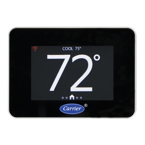
Using the Carrier® Connect™ Wi-Fi Thermostat's screens Using the Carrier® Connect™ Wi-Fi Thermostat's screens HOME The HOME screen is typically what the end user sees. Screen functions • Banner Press the center of the scrolling Banner to switch to the screen indicated by the displayed text. You can ○... -
Page 31: Setpoint
Using the Carrier® Connect™ Wi-Fi Thermostat's screens • Space Temperature — The center portion of the screen displays the sensed space temperature, in whole numbers only. Fahrenheit is the default scale but you can change to Celsius in SYSTEM SETTINGS. See To configure advanced System Settings (page 14). -
Page 32: Mode
Using the Carrier® Connect™ Wi-Fi Thermostat's screens MODE Use this screen to view and change the current MODE, including: • • HEAT • COOL • AUTO • E- HEAT NOTE The horizontal yellow bar always appears above the current mode. -
Page 33: Humidity
Using the Carrier® Connect™ Wi-Fi Thermostat's screens HUMIDITY To adjust the thermostat's humidify and dehumidify setpoints: • Drag the wheel up or down • Tap the top of the wheel to decrease the setpoint by 1% • Tap the bottom to increase the setpoint by 1%. -
Page 34: Fan
Using the Carrier® Connect™ Wi-Fi Thermostat's screens Use the following table to determine values for the terminal outputs to the equipment, when specific demands are present. NOTES • The value of X denotes that the setting may be Off or On, depending on the state of the FAN ON WITH W set on advanced SYSTEM SETTINGS screen. -
Page 35: Program
Using the Carrier® Connect™ Wi-Fi Thermostat's screens PROGRAM The top center of the screen displays the program schedule day of the week. Swipe up or down to move from one day to the next on the program schedule. The vertical yellow Row Indicator moves up and down at the same time. -
Page 36: Date And Time
Using the Carrier® Connect™ Wi-Fi Thermostat's screens DATE and TIME On this screen, scroll or tap the Orange Hour wheel or Blue Minute wheel to adjust the date and time on the thermostat. Switch to the Date Adjust screen and the Time Adjust screen using the green icon button at the right side of the screen. -
Page 37: Filter
Using the Carrier® Connect™ Wi-Fi Thermostat's screens Screen Name/Description Default and Range PROX SENSITIVITY — Change the proximity sensing feature from HIGH to MEDIUM MEDIUM to LOW. Increasing the sensitivity increases the range the sensor can detect HIGH/MEDIUM/LOW presence, but also increases the possibility of a false presence. -
Page 38: Lockout
Using the Carrier® Connect™ Wi-Fi Thermostat's screens LOCKOUT Locks out unauthorized changes made on the touchscreen. All touch interaction is locked out without the unlock code. After 5 failed attempts, a notification (fault) is sent to the registered owner of the thermostat through Wi-Fi. -
Page 39: Status
Using the Carrier® Connect™ Wi-Fi Thermostat's screens STATUS Displays the current status of • thermostat outputs • timers • stages • lockouts Current timer status is displayed and can be cleared for testing and troubleshooting by pressing and holding the TIMERS text for 5 seconds. -
Page 40: Installation Test
Installation test Installation test Complete the following to field test the Carrier® Connect™ Wi-Fi Thermostat's outputs. Press the CHANGE button to cycle the MODE screen through the following settings: HEATING (default) — not available in a cooling-only configuration ○ EM HEAT — not available unless a heat pump is configured ○... -
Page 41: Troubleshooting
Cool 1 (Heat Pump) On Cool 2 (Heat Pump) On Dehumidify Cool 1 and Dehumidify Cool 2 and Dehumidify Heat 1 (A/C) Heat 2 (A/C) Heat 1 (Heat Pump) Heat 2 (Heat Pump) Heat 3 (HP 33CONNECTSTAT43 ©2022 Carrier. Installation Guide All rights reserved. -
Page 42: Fault Definitions
NOTE Displayed only if REMOTE SENSOR is set to INDOOR or AVERAGE. HUM TEMP SENSOR HIGH Humidity sensor temperature > 122°F NOTE Displayed only if using humidity temperature as a backup source during a fault condition with the primary temperature sensor. 33CONNECTSTAT43 ©2022 Carrier. Installation Guide All rights reserved. - Page 43 Communications error occurred with Wi-Fi module (resets after valid message received) ECONOMIZER FAULT Contact closure on remote sensor input, as determined by Economizer LOCKOUT User has entered incorrect pin 5 consecutive times 33CONNECTSTAT43 ©2022 Carrier. Installation Guide All rights reserved.
-
Page 44: Recovering From A Power Outage
Resetting wi-fi access To assign a new Wi-Fi access point or transfer the Carrier® Connect™ Wi-Fi Thermostat to a new account, follow these steps. On the thermostat, not a mobile device, swipe the HOME screen twice to the left to navigate to the MODE screen and ensure the MODE is OFF. - Page 45 Use the mobile app on your phone or tablet to connect the thermostat to the desired Wi-Fi Access point. See the section of this guide titled “Registering and setting up a mobile device for enhanced access (page 9)”. Follow the instructions within the app. 33CONNECTSTAT43 ©2022 Carrier. Installation Guide All rights reserved.
-
Page 46: Compliance
Consult the dealer or an experienced radio/TV technician for help. BACnet Compliance Compliance of listed products to requirements of ASHRAE Standard 135 is the responsibility of BACnet International. BTL ® is a registered trademark of BACnet International. 33CONNECTSTAT43 ©2022 Carrier. Installation Guide All rights reserved. - Page 47 AV:507 only) Cycles Per Hour GATED_WRITE CYCLES_PER_HOUR CYCLES_HR AV:508 Max Heat Setpoint GATED_WRITE DEGREES_FAHRENHEIT MAX_HT_SP AV:509 Min Cool Setpoint GATED_WRITE DEGREES_FAHRENHEIT MIN_CL_SP AV:510 Aux Heat Lockout (HP only) GATED_WRITE DEGREES_FAHRENHEIT AUX_HT_LCKOUT AV:511 33CONNECTSTAT43 ©2022 Carrier. Installation Guide All rights reserved.
- Page 48 READ_WRITE 0=OFF NET_GP_OB_OUT BV:213 Out OB 1=ON Wi-Fi Time Synchronization READ_WRITE 0=DISABLED WIFI_TIME_SYNC BV:400 1=ENABLED Proximity Sensor Enable READ_WRITE 0=DISABLED PROXIMITY_EN BV:401 1=ENABLED Auto DST Time Shift READ_WRITE 0=DISABLED AUTO_DST BV:402 1=ENABLED 33CONNECTSTAT43 ©2022 Carrier. Installation Guide All rights reserved.
- Page 49 READ_ONLY 0=INACTIVE REM_TEMP_LO BV:903 1=ACTIVE HUM TEMP SENSOR HIGH READ_ONLY 0=INACTIVE HUM_TEMP_HI BV:904 1=ACTIVE HUM TEMP SENSOR LOW READ_ONLY 0=INACTIVE HUM_TEMP_LO BV:905 1=ACTIVE ID TEMP RANGE HIGH READ_ONLY 0=INACTIVE ID_TEMP_RNG_HI BV:906 1=ACTIVE 33CONNECTSTAT43 ©2022 Carrier. Installation Guide All rights reserved.
- Page 50 MSV:403 2=4 PARTS Occupied Fan Mode READ_WRITE 1=AUTO OCC_FAN MSV:404 2=ON Unoccupied Fan Mode READ_WRITE 1=AUTO UNOCC_FAN MSV:405 2=ON Current Fan Mode READ_WRITE 1=AUTO FAN MODE MSV:406 2=ON 3=OVERRIDE AUTO 4=OVERRIDE ON 33CONNECTSTAT43 ©2022 Carrier. Installation Guide All rights reserved.
- Page 51 General Purpose Output GATED_WRITE 1=2 MIN GP_OUT_TIMEOUT MSV:508 Timeout 2=20 MIN 3=1 HR 4=UNLIMITED Network GP Y3 Mode GATED_WRITE 1=DISABLED NET_GP_Y3_MODE MSV:509 2=ENERGIZED_ACTIVE 3=ENERGIZED_INACTIVE Network GP W2 Mode GATED_WRITE 1=DISABLED NET_GP_W2_MODE MSV:510 2=ENERGIZED_ACTIVE 3=ENERGIZED_INACTIVE 33CONNECTSTAT43 ©2022 Carrier. Installation Guide All rights reserved.
- Page 52 Appendix: BACnet Points List Point Name Point Access Units BACnet Point Name BACnet Object ID Network GP OB Mode GATED_WRITE 1=DISABLED NET_GP_OB_MODE MSV:511 2=ENERGIZED_ACTIVE 3=ENERGIZED_INACTIVE 33CONNECTSTAT43 ©2022 Carrier. Installation Guide All rights reserved.
- Page 53 Added SAT to REMOTE SENSOR C-ST-CP-E SETTINGS Added BACnet parameters 8/28/19 Humidity Removed note limiting output use C-ST-CP-E 12/2/22 Fault Definitions Added line to ID temp sensor high and low. * For internal use only 33CONNECTSTAT43 ©2022 Carrier. Installation Guide All rights reserved.
- Page 56 Carrier ©2022 · Catalog No. 11-808-728-01 · 12/2/2022...
Need help?
Do you have a question about the Connect 33CONNECTSTAT43 and is the answer not in the manual?
Questions and answers
How to access Advanced settings on the Wi-Fi carrier thermostat
To access advanced settings on the Carrier Connect 33CONNECTSTAT43 thermostat:
1. Go to the FAN screen.
2. Press and hold the Fan Button for 5 seconds to access the SYSTEM SETTINGS screen.
3. Enter the 3-digit security PIN code, if required.
4. Use the advanced options on the SYSTEM SETTINGS screens to configure and set up the system.
- Swipe up or down to navigate through options and tap to select one.
- Swipe on any SYSTEM SETTINGS sub-screen to return to the main SYSTEM SETTINGS screen.
Advanced settings can only be accessed on the thermostat itself, not through the app or web.
This answer is automatically generated
How to set humidity and remote sensor
To set the humidity and remote sensor on the Carrier Connect 33CONNECTSTAT43:
1. Remote Sensor:
- Set REMOTE SENSOR to INDOOR or AVERAGE to enable remote temperature readings.
- The thermostat will display REMOTE SENSOR HIGH if the remote temperature exceeds 122°F.
- It will display REMOTE SENSOR LOW if the remote temperature is 0°F.
2. Humidity Settings:
- Humidification Output: Select an available output (O/B, Y3, or W2) for humidifier control.
- Dehumidification Output: Select an available output (O/B, Y3, or W2) for dehumidifier (Humidi-MiZer™) control.
- Dehumidify Function: If DEHUMIDIFY = YES, the cooling setpoint will adjust automatically based on humidity levels.
- If using humidity temperature as a backup sensor, the thermostat will display HUM TEMP SENSOR HIGH if the temperature exceeds 122°F or HUM TEMP SENSOR LOW if the temperature is 0°F.
- Humidity Range Alerts: The thermostat displays HUMIDITY RANGE HIGH if humidity exceeds 90% and HUMIDITY RANGE LOW if it is below 10%.
- Hum Sensor Failure: If the humidity sensor times out, reads above 99%, or is 0%, an error will be displayed.
Ensure that the outputs selected for humidification and dehumidification are not already assigned to other functions.
This answer is automatically generated
How can I change the pin if the original pin is lost or forgotten?