
Related Manuals for SystemAir SYSLOOP 70


Summary of Contents for SystemAir SYSLOOP 70
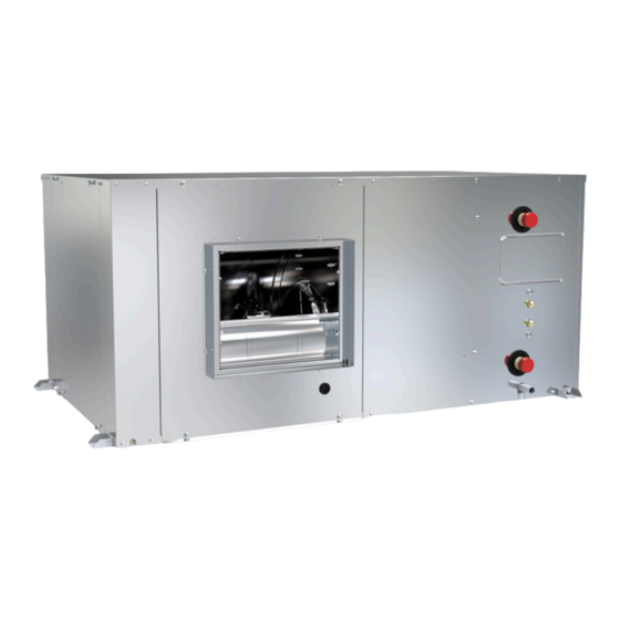
- Page 1 Installation and maintenance manual SYSLOOP 70-135 70 / 135 Water source heat pump 8.1 â 14.6kW 7.0 â 13.3kW 1 727 â 3 677m...
- Page 3 INSTALLATION INSTRUCTION English NOTICE D’INSTALLATION Français INSTALLATIONSHANDBUCH Deutsch ISTRUZIONI INSTALLAZIONE Italiano INSTRUCCIONES DE INSTALACIÓN Español...
-
Page 4: Table Of Contents
2 SYSLOOP 70-135 CONTENTS 1. GENERAL RECOMMENDATIONS ................................ 3 1.1. SAFETY DIRECTIONS ............................................3 1.2. WARNING ................................................. 3 1.3. EQUIPMENT SAFETY DATA ..........................................4 2. INSPECTION AND STORAGE ................................5 3. WARRANTY ...................................... 5 4. TECHNICAL SUPPORT AND AFTER-SALES SERVICE HOTLINE ......................5 5. -
Page 5: General Recommendations
SYSLOOP 70-135 POWER SUPPLY MUST BE SWITCHED OFF BEFORE STARTING WORK IN THE ELECTRIC CONTROL 1. GENERAL RECOMMENDATIONS The purpose of this Manual is to provide users with instructions for installing, commissioning, using and maintaining the units. It also contains instructions on starting up the machine as well as recommendations to avoid bodily injury and risks of damage to the device during its operation. -
Page 6: Equipment Safety Data
4 SYSLOOP 70-135 1.3. EQUIPMENT SAFETY DATA Safety data R513A Toxicity level Low. Dermal contact with the rapidly evaporating liquid can cause frostbite to the tissue. In the event In contact with the skin of contact with the liquid, warm the frozen tissue with water and notify a physician. Remove contaminated clothing and shoes. -
Page 7: Inspection And Storage
For technical questions, work under warranty, commissioning, a manufacturer’s visit or repair quotations. Our technical support and after-sales service hotline can be reached on: (0)891 700 407 in France ² support@systemair.fr for export customers ² 5. PRESENTATION The SYSLOOP units are produced in compliance with state-of-the-art design and manufacturing standards. -
Page 8: Contents Of Package
6 SYSLOOP 70-135 6. CONTENTS OF PACKAGE Package contents: appliance suspension kit comprising: 4 nuts 4 shock mounts ² ² 4 locknuts 4 washers ² ² installation manual 6.1. OPTIONAL ACCESSORIES RCS control module On opening the box, check that all of the accessories required for installation are present. -
Page 9: Technical Specifications
SYSLOOP 70-135 9. TECHNICAL SPECIFICATIONS 9.1. MODELS DESIGNATION SL70 . HP . SYS . EC . G2M1 . POL423 . EH3750 . MBRT . SECT . S1 . RCS . 2W . FS . RS . IP REP. Description SL70... -
Page 10: Physical Characteristics
8 SYSLOOP 70-135 9.2. PHYSICAL CHARACTERISTICS 9.2.1. SYSLOOP - EC MOTOR Models Total cooling capacities (1) 7 011 8 407 10 290 11 183 12 105 13 301 Sensible cooling capacities (1) 5 960 7 146 8 541 9 282... -
Page 11: Electric Specifications
SYSLOOP 70-135 9.3. ELECTRIC SPECIFICATIONS A variance of ±10% is acceptable in relation to the operating voltage marked on the appliance’s Maker’s Plate. Phase imbalance on three phase units must not exceed 2%. Operating voltages : 400V / 3~ N / 50Hz (360 Volts mini ; 440 Volts maxi.) ²... -
Page 12: Flow Limits
10 SYSLOOP 70-135 9.4.2. FLOW LIMITS 14 15 16 17 18 19 20 21 22 23 24 25 26 27 28 29 30 31 32 33 15°C wb 24°C wb Air inlet temperature (°C db) MODELS Nominal air flow *... -
Page 13: Refrigeration Specifications
Refrigerating fluids must be handled by skilled personnel. Caution SYSLOOP 70-135 units use the R513A fluoro-carbonated fluid, belonging to group 2 as defined in directive 2014/68/UE. Considering the maximum operating pressure of these units (18 bar g), they integrate category 2 (or lower) components as defined in directive 2014/68/UE. -
Page 14: Installation
12 SYSLOOP 70-135 10. INSTALLATION Caution The unit is not designed to withstand weights or stresses from adjacent equipment, pipe work or constructions. Any foreign weight or stress on the unit structure could lead to a malfunction or damage, which could prove hazardous to personnel and property. In such an event, the warranty shall be voided. -
Page 15: Unit Location
SYSLOOP 70-135 10.3. UNIT LOCATION Caution The unit base shall be arranged as indicated in the manual. There could be a risk of personal injury or damage to property in the event of the unit being incorrectly supported. SYSLOOP 70-135 1. -
Page 16: Ducting And Noise Level Reduction
14 SYSLOOP 70-135 11. DUCTING AND NOISE LEVEL REDUCTION Water circuit heat pumps are usually installed in conjunction with an air blowing duct. A return air duct may also be required. All ductwork shall be compliant with best air conditioning engineering practices. -
Page 17: Air Blowing Frame And Return Air Intake Frame
SYSLOOP 70-135 11.1. AIR BLOWING FRAME AND RETURN AIR INTAKE FRAME RETURN AIR INTAKE (IN LINE) AIR FILTER IN LINE BLOWING (S1) (STANDARD CONFIGURATION) REAR BLOWING (S2) 11.2. MODIFYING THE AIR BLOWING DIRECTION The unit SYSLOOP can be supplied configured for either frontal air blowing, known as "IN LINE", or for side air blowing, known as "REAR". -
Page 18: Filter Access
16 SYSLOOP 70-135 11.3. FILTER ACCESS Each unit is supplied with a connection frame also serving as the filter support. This enables to filter to be removed from the side without having to dismantle the duct or the connection frame. -
Page 19: Sl70.Ec / Sl85.Ec
SYSLOOP 70-135 11.5.1. SL70.EC / SL85.EC Ductwork curve 1000 1500 2000 2500 3000 3500 4000 Air flow (m : low speed : high speed : medium speed 11.5.2. SL100.EC / SL110.EC Ductwork curve 1000 1500 2000 2500 3000 3500 4000... -
Page 20: Sl120.Ec / Sl135.Ec
18 SYSLOOP 70-135 11.5.3. SL120.EC / SL135.EC Ductwork curve 1000 1500 2000 2500 3000 3500 4000 Air flow (m : low speed : high speed : medium speed... -
Page 21: Hydraulic Links
Caution The SYSLOOP 70-135 must not run on a network with open loops, likely to cause incidents related to oxygenation, or with non treated table water. Using improperly treated or non treated water in the SYSLOOP 70-135 may cause scaling, erosion, corrosion or algae or sludge deposits in the exchangers. -
Page 22: Recommendations For Hydraulic Connections
20 SYSLOOP 70-135 12.2. RECOMMENDATIONS FOR HYDRAULIC CONNECTIONS 1. It is recommended that all units are connected to a water supply and return pipe system of the Tickelman Loop type. The Tickelman Loop system is self-balancing and thus only requires manual balancing if a large number of units with different flow and pressure loss characteristics are connected to a single hydraulic loop. - Page 23 SYSLOOP 70-135 6. Certain flexible hose threaded connectors are supplied with sealing paste. If this is not the case, use Teflon tape to create a tight seal. 7. Each unit must be equipped with isolation valves on the water inlet and outlet pipes. The return isolation valve is used for both cutting off the water supply and balancing the installation’s water...
-
Page 24: Recommendations For Cleaning And Flushing Out The System
22 SYSLOOP 70-135 12.3. RECOMMENDATIONS FOR CLEANING AND FLUSHING OUT THE SYSTEM 1. Before commissioning an appliance for the first time, the water loop must be cleaned and rinsed out to remove any dirt and manufacturing debris. If the appliances are equipped with isolation valves (either electric or pressostatic), the water... -
Page 25: Wiring Diagram And Legend
SYSLOOP 70-135 13. WIRING DIAGRAM AND LEGEND 13.1. WIRING DIAGRAM SEE APPENDIX SE4978 SYSLOOP 70-85-100-110-120-135 EC motor Control Siemens POL423 400V / 3~ N / 50Hz 13.2. WIRING DIAGRAM KEY DESCRIPTIONS SEE APPENDIX 13.3. POWER SUPPLY The power supply is from a single point at the main terminal X1 or at the optional disconnecting switch QG- 0.1 (copper cable recommended) -
Page 26: Unit Power Supply
24 SYSLOOP 70-135 VERY IMPORTANT: 3N~400V-50HZ The SYSLOOP unit is equipped as standard with a phase FPC-0.1 sequence and cut-out controller located in the electrical box. THE LEDS INDICATE THE FOLLOWING CONDITIONS: Green LED = 1 Green LED = 1... -
Page 27: Alarm Indicators
SYSLOOP 70-135 SIEMENS 14.2. ALARM INDICATORS The SYSLOOP control system has a dedicated alarm indicator. This information is available via a dry contact (Normally Closed) by connecting to the unit’s terminals 6 and 7. -FF-0.1 POL423.50 STD 24...230V 24...230V 24...230V 24...230V... -
Page 28: Communication
26 SYSLOOP 70-135 14.4. COMMUNICATION The SYSLOOP has two different communication protocols: Modbus RTU ² BACNet MS/TP ² A+ B-REF Modbus RTU or BACnet MS/TP communications are via the RS485 connection on the controller (terminals A+ and B+) and a BUS type cable (1 twisted pair, shielded) with a 0.22 mm²... -
Page 29: Electrical Connections
SYSLOOP 70-135 14.5.2. ELECTRICAL CONNECTIONS The control return must be connected as per the following diagrams. For the connection, use a KNX TP1 type cable (Twisted pair with insulation) with a 0.8mm² cross-section. SYSLOOP - AUTONOMOUS Lmax = 100 M... -
Page 30: Regulation
28 SYSLOOP 70-135 15. REGULATION SYSLOOP units are fitted with an electronic control system. It provides the command, control and alarm functions. 15.1. ORDER OF PRIORITY FOR CONTROL SYSTEMS The integrated regulator in the SYSLOOP can be controlled by various interfaces and systems. The order of... -
Page 31: Screen
SYSLOOP 70-135 15.2.2. SCREEN Icons Meanings AUTO 23.5 SYSLOOP off °C Hourly programming active 05:30 AUTO month year Operation in Eco mode Operation in Comfort mode COOL mode HEAT Mode Auto-changeover mode. The control displays the active heat control mode. -
Page 32: Scheduling
30 SYSLOOP 70-135 15.2.4. SCHEDULING Scheduling is used to select the unit activation and shutdown times. Each day is broken down into 6 time slots set by Selected time slot mode A start time ² A state: ON or OFF ²... -
Page 33: Final Tasks
SYSLOOP 70-135 16. FINAL TASKS Place the plugs back on the valves and check that they are properly tightened. If needed, fix the cables and the pipes on the wall with clamping collars. Operate the SYSLOOP in the presence of the user and explain all functions. -
Page 34: Commissioning
32 SYSLOOP 70-135 17.1. COMMISSIONING After performing all the above-mentioned checks, proceed with creating a demand for Cooling and Heating or vice versa. 17.1.1. DEMAND FOR COOLING 1. With the key on the control module, select COOL mode and then set the minimum temperature with the UP and DOWN arrows. -
Page 35: Maintenance And Servicing
SYSLOOP 70-135 18. MAINTENANCE AND SERVICING Maintenance in accordance with our instructions will prolong the service life of your SYSLOOP : Better refrigeration performance ² Reduced power consumption ² Accidental component breakage prevention ² Prevention of heavy, late, and expensive maintenance work ²... -
Page 36: Air Filter
34 SYSLOOP 70-135 18.1.5. AIR FILTER In order for the installation to operate correctly, it is essential to regularly clean the air filter located in the intake of the indoor unit. When clogged, the filter reduces the air flow through the heat exchanger of the indoor unit, which in turn reduces the efficiency of the installation and inhibits the cooling of the fan motor. -
Page 37: Fault Finding
SYSLOOP 70-135 18.2. FAULT FINDING 18.2.1. NEITHER THE FAN NOR THE COMPRESSOR OPERATE 1. The system is in alarm mode when the mains power supply is switched on. Check the points mentioned in § ALARM CODES, page 36 for diagnosis. -
Page 38: Appearance Of Abnormal Noises And Vibrations In The Casing
36 SYSLOOP 70-135 18.2.6. APPEARANCE OF ABNORMAL NOISES AND VIBRATIONS IN THE CASING 1. Check that the turbine is not rubbing against the scroll and that the latter is not damaged. Replace as required. 2. Check that the turbine has not worked loose on its shaft. Centre the turbine and tighten it as required. -
Page 39: Warranty Claim - Material Return Procedure
SYSLOOP 70-135 19. WARRANTY CLAIM - MATERIAL RETURN PROCEDURE Equipment must not be returned without the permission of our After Sales Department. To return the equipment, contact your nearest sales office (Refer to the § TECHNICAL SUPPORT AND AFTER- SALES SERVICE HOTLINE, page 5) and ask for a "return form". The return form shall be sent with the returned equipment and shall contain all necessary information concerning the problem encountered. - Page 40 38 SYSLOOP 70-135...
- Page 41 APPENDIX / ANNEXE / ANLAGE / ALLEGATO / ANEXO APPENDIX ANNEXE ANLAGE ALLEGATO ANEXO...
- Page 42 SL70.EC.S1 / SL85.EC.S1 ................III WIRING DIAGRAM ...............XI SL70.EC.S2 / SL85.EC.S2 ................IV LEGEND ......................XII SL100.EC.S1 / SL110.EC.S1 ................V SYSLOOP 70-135 EC MOTOR ..............XIII SL100.EC.S2 / SL110.EC.S2 ................VI SL120.EC.S1 / SL135.EC.S1 ................VII SL120.EC.S2 / SL135.EC.S2 .................VIII ANNEXE DIMENSIONS ................III...
- Page 43 APPENDIX / ANNEXE / ANLAGE / ALLEGATO / ANEXO DIMENSIONS DIMENSIONS ABMESSUNGEN DIMENSIONI DIMENSIONES SL70.EC.S1 / SL85.EC.S1 OUTLET WATER INTLET Ø1˝ Gas male Ø19 SYSLOOP 70-135...
- Page 44 APPENDIX / ANNEXE / ANLAGE / ALLEGATO / ANEXO SL70.EC.S2 / SL85.EC.S2 OUTLET WATER INTLET Ø1˝ Gas male Ø19 IV SYSLOOP 70-135...
- Page 45 APPENDIX / ANNEXE / ANLAGE / ALLEGATO / ANEXO SL100.EC.S1 / SL110.EC.S1 OUTLET WATER INTLET Ø1˝ Gas male Ø19 SYSLOOP 70-135...
- Page 46 APPENDIX / ANNEXE / ANLAGE / ALLEGATO / ANEXO SL100.EC.S2 / SL110.EC.S2 OUTLET WATER INTLET Ø1˝ Gas male Ø19 VI SYSLOOP 70-135...
- Page 47 APPENDIX / ANNEXE / ANLAGE / ALLEGATO / ANEXO SL120.EC.S1 / SL135.EC.S1 OUTLET WATER INTLET Ø1˝ Gas male Ø19 SYSLOOP 70-135...
- Page 48 APPENDIX / ANNEXE / ANLAGE / ALLEGATO / ANEXO SL120.EC.S2 / SL135.EC.S2 OUTLET WATER INTLET Ø1˝ Gas male Ø19 VIII SYSLOOP 70-135...
- Page 49 RAT-0.1 RAT-0.1 : Sensore di temperatura dell’aria : Sonda de temperatura de aire Y-1.1 Valvola circuito dell’acqua Y-1.1 Válvula de parada hidráulica (optional) (optional) SW-0.1 Rivelatore di livello d’acqua di SW-0.1 Rivelatore di livello d’acqua di condensazione condensazione SYSLOOP 70-135...
- Page 50 APPENDIX / ANNEXE / ANLAGE / ALLEGATO / ANEXO PSHP-1.1 WATER R513A RV-1.1 C-1.1 LWT-0.1 PSLP-1.1 EH-0.1 IF-0.1 FILTER RAT-0.1 Y-1.1 FS-0.1 ICT-0.1 SW-0.1 X SYSLOOP 70-135...
- Page 51 MISE HORS TENSION OBLIGATOIRE AVANT TOUTE INTERVENTION DANS LES BOITIERS ELECTRIQUES. VOR JEDEM EINGRIFF AN DEN ANSCHLUßKÄSTEN UNBEDINGT DAS GERÄT ABSCHALTEN! PRIMA DI OGNI INTERVENTO SULLE CASSETTE ELETTRICHE ESCLUDERE TASSATIVAMENTE L’ALIMENTAZIONE ! PUESTA FUERA DE TNESIÓN OBLIGATORIA ANTES DE CUALQUIER INTERVENCIÓN EN LAS CAJAS ELÉCTRICAS! SYSLOOP 70-135...
- Page 52 APPENDIX / ANNEXE / ANLAGE / ALLEGATO / ANEXO LEGEND XII SYSLOOP 70-135...
- Page 53 APPENDIX / ANNEXE / ANLAGE / ALLEGATO / ANEXO SYSLOOP 70-135 EC MOTOR NC N SYSLOOP 70-135 XIII...
- Page 54 APPENDIX / ANNEXE / ANLAGE / ALLEGATO / ANEXO XIV SYSLOOP 70-135...
- Page 55 Contact: ................: ................... COMMISSIONING INFORMATION: Company: ................Address: ................................... Contact: ................: ................... UNIT IDENTIFICATION: SYSLOOP 70-135 Unit serial number: ................. Motorised water valve General fault return relay Flow switch RCS supervision control unit Circuit breaker MODBUS supervision...
- Page 56 Air outlet temperature °C °C REMARKS: ............................................................................................................................................................................................................................................................................................................................................................................................................................................................................................................................................................................................................................................................................................................................................................................................................................................................................................................................................................................................................................................................................................................................................................................................DATE: DATE: TECNICIAN: CLIENT Name: Name: Sign-in: Sign-in: XVI SYSLOOP 70-135...
- Page 58 As part of our ongoing product improvement programme, our products are subject to change without prior notice. Non contractual photos. Systemair AC SAS Route de Verneuil 27570 Tillières-sur-Avre FRANCE & : +33 (0)2 32 60 61 00 6 : +33 (0)2 32 32 55 13...
Need help?
Do you have a question about the SYSLOOP 70 and is the answer not in the manual?
Questions and answers