
Related Manuals for SystemAir SysLoop 15


Summary of Contents for SystemAir SysLoop 15
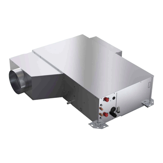
- Page 1 Installation and maintenance manual SysLoop 15 / 30 Water source heat pump 1.93 â 3.68kW 1.51 â 2.90kW 435 â 525 m...
- Page 3 INSTALLATION INSTRUCTION English NOTICE D’INSTALLATION Français INSTALLATIONSHANDBUCH Deutsch ISTRUZIONI INSTALLAZIONE Italiano INSTRUCCIONES DE INSTALACIÓN Español...
-
Page 4: Table Of Contents
2 SysLoop CONTENTS 1. GENERAL RECOMMENDATIONS ................................ 3 1.1. SAFETY DIRECTIONS ............................................3 1.2. WARNING ................................................. 3 1.3. EQUIPMENT SAFETY DATA ..........................................4 2. INSPECTION AND STORAGE ................................5 3. WARRANTY ...................................... 5 4. CONTENTS OF PACKAGE ................................... 5 5. DIMENSIONS ....................................5 6. -
Page 5: General Recommendations
SysLoop POWER SUPPLY MUST BE SWITCHED OFF BEFORE STARTING WORK IN THE ELECTRIC CONTROL BOX 1. GENERAL RECOMMENDATIONS The purpose of this Manual is to provide users with instructions for installing, commissioning, using and maintaining the units. It also contains instructions on starting up the machine as well as recommendations to avoid bodily injury and risks of damage to the device during its operation. -
Page 6: Equipment Safety Data
4 SysLoop 1.3. EQUIPMENT SAFETY DATA Safety Data R410A Toxicity Skin contact with the rapidly evaporating liquid may cause tissue chilblains. In case of skin contact with In contact with skin the liquid, warm the frozen tissue with water and call a doctor. Remove contaminated clothing and footwear. -
Page 7: Inspection And Storage
SysLoop 2. INSPECTION AND STORAGE At the time of receiving the equipment carefully cross check all the elements against the shipping documents in order to ensure that all the crates and boxes have been received. Inspect all the units for any visible or hidden damage. -
Page 8: Refrigeration Specifications
6 SysLoop 7. REFRIGERATION SPECIFICATIONS 7.1. REFRIGERANT CIRCUIT DIAGRAM SEE APPENDIX 7.2. REFRIGERANT CHARGE Caution This equipment contains fluorinated gas with greenhouse gas effects covered by the Kyoto agreement. The type and quantity of refrigerating fluid per circuit are indicated on the product plate. The installer and end user will get informed on local environmental regulations for the installation, operation and disposal of the equipment ;... -
Page 9: Technical Specifications
SysLoop 8. TECHNICAL SPECIFICATIONS 8.1. OPERATING LIMITS 8.1.1. ENVIRONMENT This equipment is designed EXCLUSIVELY for INDOOR installation. In general, sheltered locations such as garages, roof space, etc, do not provide sufficient protection against extreme temperatures and/or humidity and may be harmful to the unit’s performance, reliability and service life. -
Page 10: Electric Specifications
8 SysLoop 9. ELECTRIC SPECIFICATIONS 9.1. ELECTRICAL POWER SUPPLY A variance of ±10% is acceptable in relation to the operating voltage marked on the appliance’s Maker’s Plate. Operating voltages: 230V / 1 ph / 50 Hz (207 Volts minimum; 253 Volts maximum.) ²... -
Page 11: Clearance
SysLoop 10.2. CLEARANCE 600mm 600mm 600mm 600mm 200mm 10.3. UNIT LOCATION Caution The unit base shall be arranged as indicated in the manual. There could be a risk of personal injury or damage to property in the event of the unit being incorrectly supported. Install the unit in a location allowing easy removal of the filter and the access panels to the electrical box/ compressor and fan by leaving sufficient free space... -
Page 12: Ducting And Noise Level Reduction
10 SysLoop 11. DUCTING AND NOISE LEVEL REDUCTION Water circuit heat pumps are usually installed in conjunction with an air blowing duct. A return air duct may also be required. All ductwork shall be compliant with best air conditioning engineering practices. The air blowing duct system normally consists of a flexible connector mounted on the unit, a bridging section to link to the size of the main duct, a short section of straight duct, an elbow without a damper and a main duct with spurs equipped with distribution grilles as illustrated in the drawing below. -
Page 13: Air Blowing Frame And Return Air Intake Frame
SysLoop 11.1. AIR BLOWING FRAME AND RETURN AIR INTAKE FRAME RETURN AIR INTAKE (IN LINE) AIR FILTER 225X366X23 RETURN AIR INTAKE IN LINE BLOWING (REAR) (STANDARD CONFIGURATION) 11.2. AIR BLOWING PLENUM AND RETURN AIR INTAKE PLENUM RETURN AIR INTAKE (IN LINE) AIR FILTER 366X225X23 RETURN AIR INTAKE... -
Page 14: Air Discharge Modification
12 SysLoop 11.3. AIR DISCHARGE MODIFICATION The units can be delivered configured either for frontal air return, known as "In LINE" or for side air return. It is also possible to modify the return air configuration onsite by proceeding as follows: 1. -
Page 15: Aeraulic Adjustement
SysLoop 11.6. AERAULIC ADJUSTEMENT : External static pressure at the air intake : External static pressure at blowing EXTERNAL STATIC PRESSURE = P2-P1 Caution External static pressure at the air intake above -100Pa External static pressure at blowing less than 100Pa 11.6.1. -
Page 16: Models Sl20 - Sl30
14 SysLoop 12.6.2. MODELS SL20 - SL30 BASIC FILTER - WITHOUT PLENUN BASIC FILTER - WITH PLENUM SL20 SL20 Ductwork SL30 curve SL30 Ductwork curve Air flow (m Air flow (m G3 FILTER - WITHOUT PLENUN G3 FILTER - WITH PLENUM Ductwork curve SL20... -
Page 17: Hydraulic Links
SysLoop 13. HYDRAULIC LINKS Caution THE WARRANTY DOES NOT COVER DAMAGE DUE TO CORROSION RESULTING FROM ELECTROLYTIC PHENOMENA. 13.1. WATER QUALITY The water must be analyzed; the hydraulic network system installed must include all elements necessary for water treatment: filters, additives, intermediate exchangers, drain valves, vents, check valves, etc., according to the results of the analysis. -
Page 18: Recommendations For Hydraulic Connections
16 SysLoop 13.2. RECOMMENDATIONS FOR HYDRAULIC CONNECTIONS 1. It is recommended that all units are connected to a water supply and return pipe system of the Tickelman Loop type. The Tickelman Loop system is self-balancing and thus only requires manual balancing if a large number of units with different flow and pressure loss characteristics are connected to a single hydraulic loop. - Page 19 SysLoop 6. Certain flexible hose threaded connectors are supplied with sealing paste. If this is not the case, use Teflon tape to create a tight seal. 7. Each unit must be equipped with isolation valves on the water inlet and outlet pipes. The return isolation valve is used for both cutting off the water supply and balancing the installation’s water flow.
-
Page 20: Recommendations For Cleaning And Flushing Out The System
18 SysLoop 13.3. RECOMMENDATIONS FOR CLEANING AND FLUSHING OUT THE SYSTEM 1. Before commissioning an appliance for the first time, the water loop must be cleaned and rinsed out to remove any dirt and manufacturing debris. If the appliances are equipped with isolation valves (either electric or pressostatic), the water supply and return conveyance circuits to and from INTERCONNECTED CONVEYANCES each machine must be connected to each other. -
Page 21: Wiring Diagram And Legend
SysLoop 14. WIRING DIAGRAM AND LEGEND 14.1. WIRING DIAGRAM SEE APPENDIX SE4760 models SL15/SL20/SL30 EC motor Control Siemens 230V 50Hz +/- 10% SE4779 models SL15/SL20/SL30 EC motor Control Storm 2 230V 50Hz +/- 10% 14.2. LEGEND N 823 SEE APPENDIX 14.2.1. -
Page 22: Generalities
20 SysLoop 15.1. GENERALITIES Ensure that the available electrical power supply and the network frequency are matched to the required operating current, taking account of the appliance’s specific location and the current required to supply any other appliances connected to the same circuit. 1. -
Page 23: Electrical Connections
SysLoop 15.2.2. ELECTRICAL CONNECTIONS The control return must be connected as per the following diagrams. For the connection, use a KNX TP1 type cable (Twisted pair with insulation) with a 0.8mm² cross-section. SYSLOOP - AUTONOMOUS Lmax = 700 M SYSLOOP - MASTER/SLAVES 15 regulators maximum Lmax = 700 M... -
Page 24: Regulation
22 SysLoop 16. REGULATION SysLoop units are fitted with an electronic control system. It provides the command, control and alarm functions. 16.1. ORDER OF PRIORITY FOR CONTROL SYSTEMS The integrated regulator in the SysLoop can be controlled by various interfaces and systems. The order of priority for each drive system is as follows: Timing programming: this scheduling is integrated in the regulator The BMS : the remote supervision transmits it commands according to the communication protocols... -
Page 25: Screen
SysLoop 16.2.2. SCREEN Icons Meanings AUTO 23.5 SysLoop off °C Hourly programming active 05:30 AUTO month year Operation in Eco mode Operation in Comfort mode COOL mode HEAT Mode Auto-changeover mode. The control displays the active heat control mode. Ventilation only When the unit is off, the temperature displayed is that measured by the control’s internal 23.5 °C... -
Page 26: Scheduling
24 SysLoop 16.2.4. SCHEDULING Scheduling is used to select the unit activation and shutdown times. Each day is broken down into 6 time slots set by Selected time slot mode A start time ² A state: ON or OFF ² 05:30 Time slot start ... -
Page 27: Final Tasks
SysLoop 17. FINAL TASKS Place the plugs back on the valves and check that they are properly tightened. If needed, fix the cables and the pipes on the wall with clamping collars. Operate the SysLoop in the presence of the user and explain all functions. Show him how to remove, clean and place back the filters. -
Page 28: Commissioning
26 SysLoop 18.1. COMMISSIONING After performing all the above-mentioned checks, proceed with creating a demand for Cooling and Heating or vice versa. 18.1.1. DEMAND FOR COOLING 1. With the key on the control module, select COOL mode and then set the minimum temperature with the UP and DOWN arrows. -
Page 29: Maintenance And Servicing
SysLoop 19. MAINTENANCE AND SERVICING 1. Normal maintenance of the appliances is generally limited to replacing filters. 2. The filters must be changed at regular intervals. The frequency is dependent on the specific application conditions. Certain installations, for example in hotels where there large amounts of fluff due to the frequent bedding changes and the presence of fitted carpets, require more frequent filter changes. -
Page 30: Insufficient Cooling Or Heating Production
28 SysLoop 19.1.3. INSUFFICIENT COOLING OR HEATING PRODUCTION 1. Check that the thermostat is properly located in the zone to be heated or cooled and that it is not near to a source of cold or heat that may influence the reading. 2. -
Page 31: Alarm Codes
SysLoop 19.2. ALARM CODES Code Type Message HP pressure switch LP pressure switch water min. temperature cool mode alarm water max. temperature cool mode water min. temperature heat mode water max. temperature heat mode alarm RAT sensor defective alarm ICT sensor defective alarm LWT sensor defective alarm... - Page 32 30 SysLoop...
- Page 33 APPENDIX / ANNEXE / ANLAGE / ALLEGATO / ANEXO APPENDIX ANNEXE ANLAGE ALLEGATO ANEXO...
- Page 34 APPENDIX / ANNEXE / ANLAGE / ALLEGATO / ANEXO APPENDIX DIMENSIONS ................III CONFIGURATION R1.AI 1Ø200/S4.AO 1Ø200 OR R1.AI 1Ø200 FAØ100/S4.AO 1Ø200 OR CONFIGURATION R1.AI RECT/S4.AO RECT ........... III R1.AI 1Ø200 FAØ125/S4.AO 1Ø200 OR CONFIGURATION R2.AI RECT/S4.AO RECT ........... IV R1.AI 1Ø200/S3.AO 1Ø200 OR CONFIGURATION R1.AI 1Ø200/S4.AO RECT OR R1.AI 1Ø200 FAØ100/S3.AO 1Ø200 OR R1.AI 1Ø200 FAØ100/S4.AO RECT OR...
- Page 35 APPENDIX / ANNEXE / ANLAGE / ALLEGATO / ANEXO DIMENSIONS DIMENSIONS ABMESSUNGEN DIMENSIONI DIMENSIONES CONFIGURATION R1.AI RECT/S4.AO RECT Ø 1/2“ Gas male 917.5 R1.AI RECT S4.AO RECT SysLoop...
- Page 36 APPENDIX / ANNEXE / ANLAGE / ALLEGATO / ANEXO CONFIGURATION R2.AI RECT/S4.AO RECT Ø 1/2“ Gas male 917.5 1030 S4.AO RECT R2.AI RECT IV SysLoop...
- Page 37 APPENDIX / ANNEXE / ANLAGE / ALLEGATO / ANEXO CONFIGURATION R1.AI 1Ø200/S4.AO RECT OR R1.AI 1Ø200 FAØ100/S4.AO RECT OR R1.AI 1Ø200 FAØ125/S4.AO RECT Ø 1/2“ Gas male 917.5 R1.AI 1Ø200 FAØ100 R1.AI 1Ø200 FAØ125 R1.AI 1Ø200 S4.AO RECT SysLoop...
- Page 38 APPENDIX / ANNEXE / ANLAGE / ALLEGATO / ANEXO CONFIGURATION R2.AI 1Ø200/S4.AO RECT OR R2.AI 1Ø200 FAØ100/S4.AO RECT OR R2.AI 1Ø200 FAØ125/S4.AO RECT Ø 1/2“ Gas male 917.5 1031 S4.AO RECT R2.AI 1Ø200 R2.AI 1Ø200 FAØ100 R2.AI 1Ø200 FAØ125 VI SysLoop...
- Page 39 APPENDIX / ANNEXE / ANLAGE / ALLEGATO / ANEXO CONFIGURATION R1.AI RECT/S4.AO 1Ø200 OR R1.AI RECT/S3.AO 1Ø200 Ø 1/2“ Gas male 917.5 R1.AI RECT S4.AO 1Ø200 R1.AI RECT 1004 S3.AO 1Ø200 SysLoop...
- Page 40 APPENDIX / ANNEXE / ANLAGE / ALLEGATO / ANEXO CONFIGURATION R2.AI RECT/S4.AO 1Ø200 OR R2.AI RECT/S3.AO 1Ø200 Ø 1/2“ Gas male 917.5 S4.AO 1Ø200 R2.AI RECT 1030 R2.AI RECT S3.AO 1Ø200 VIII SysLoop...
- Page 41 APPENDIX / ANNEXE / ANLAGE / ALLEGATO / ANEXO CONFIGURATION R1.AI 1Ø200/S4.AO 1Ø200 OR R1.AI 1Ø200 FAØ100/S4.AO 1Ø200 OR R1.AI 1Ø200 FAØ125/S4.AO 1Ø200 OR R1.AI 1Ø200/S3.AO 1Ø200 OR R1.AI 1Ø200 FAØ100/S3.AO 1Ø200 OR R1.AI 1Ø200 FAØ125/S3.AO 1Ø200 Ø 1/2“ Gas male 917.5 R1.AI 1Ø200 FAØ100 R1.AI 1Ø200 FAØ125...
- Page 42 APPENDIX / ANNEXE / ANLAGE / ALLEGATO / ANEXO CONFIGURATION R2.AI 1Ø200/S4.AO 1Ø200 OR R2.AI 1Ø200 FAØ100/S4.AO 1Ø200 OR R2.AI 1Ø200 FAØ125/S4.AO 1Ø200 OR R2.AI 1Ø200/S3.AO 1Ø200 OR R2.AI 1Ø200 FAØ100/S3.AO 1Ø200 OR R2.AI 1Ø200 FAØ125/S3.AO 1Ø200 Ø 1/2“ Gas male 917.5 R2.AI 1Ø200 S4.AO 1Ø200...
- Page 43 APPENDIX / ANNEXE / ANLAGE / ALLEGATO / ANEXO WIRING DIAGRAM SCHEMAS ELECTRIQUES STROMLAUFPLANS SCHEMA ELETRICO ESQUEMA ELECTRICO TAKE CARE! These wiring diagrams are correct at the time of publication. Manufacturing changes can lead to modifications. Always refer to the diagram supplied with the product. ATTENTION Ces schémas sont corrects au moment de la publication.
- Page 44 APPENDIX / ANNEXE / ANLAGE / ALLEGATO / ANEXO LEGEND XII SysLoop...
- Page 45 APPENDIX / ANNEXE / ANLAGE / ALLEGATO / ANEXO SysLoop XIII...
- Page 46 APPENDIX / ANNEXE / ANLAGE / ALLEGATO / ANEXO XIV SysLoop...
- Page 47 APPENDIX / ANNEXE / ANLAGE / ALLEGATO / ANEXO START UP FORM / FICHE DE MISE EN SERVICE CUSTOMER INFORMATION: Order number: ..............Job name: ................. Contractor: ................Installation address: ............................... Contact: ................: ................... INSTALLER INFORMATION: Company: ................Address: ...................................
- Page 48 APPENDIX / ANNEXE / ANLAGE / ALLEGATO / ANEXO INSTALLATION MEASUREMENTS: Ambient temperature: ............Ambient pressure: ............ELECTRICAL MEASUREMENTS: Voltage (L-N): ..............Nominal current (L): ............Remote On/Off dry contact OPERATING READINGS: COOLING MODE HEATING MODE Water loop system °C °C Water flow Water inlet temperature...
- Page 50 As part of our ongoing product improvement programme, our products are subject to change without prior notice. Non contractual photos. Systemair AC SAS Route de Verneuil 27570 Tillières-sur-Avre FRANCE & : +33 (0)2 32 60 61 00 6 : +33 (0)2 32 32 55 13...
Need help?
Do you have a question about the SysLoop 15 and is the answer not in the manual?
Questions and answers