Table of Contents
Advertisement
Quick Links
Installation and maintenance manual
Manuel d'installation et de maintenance
Installations- und Wartungshandbuch
Manuale di installazione e di manutenzione
Manual de instalación y de mantenimiento
Инструкция по монтажу и техобслуживанию
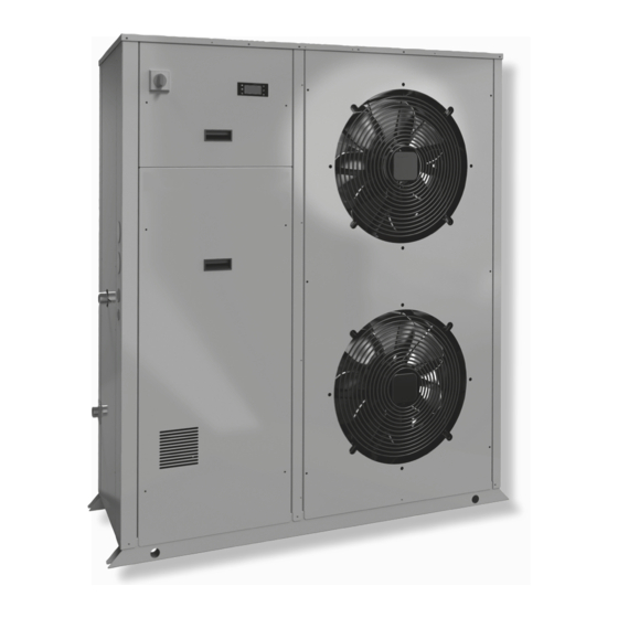
SYSCROLL 20-30 AIR EVO HP
English
Air Cooled Water Chillers and Heat Pumps
7
Refroidisseurs de liquide à condensation par air et pompes à chaleur air-eau
33 kW
Luftgekühlte Flüssigkeitskühler und Wärmepumpen
Refrigeratori d'Acqua e Pompe di Calore Raffreddati ad Aria
7
Enfriadores de Agua y Bomba de Calor Condensadas con Aire
35 kW
Водяные чиллеры с воздушным охлаждением и тепловые насосы
Part number / Code / Code / Codice / Código / Номер детали:
Supersedes / Annule et remplace / Annulliert und ersetzt / Annulla e sostituisce / Anula y
sustituye / Замена:
Notified Body / Organisme Notifié / Benannte Zertifizierungsstelle / Organismo
Notificato / Organismo Notificado / Уведомленный орган N°. 0425
Français
Deutsch
364321/I
Italiano
Español
364321/J
ISO 9001:2015 certified management system
Русское
издание
Advertisement
Table of Contents

Related Manuals for SystemAir SYSCROLL 20 AIR EVO HP


Summary of Contents for SystemAir SYSCROLL 20 AIR EVO HP
- Page 1 Installation and maintenance manual Manuel d’installation et de maintenance Installations- und Wartungshandbuch Manuale di installazione e di manutenzione Manual de instalación y de mantenimiento Инструкция по монтажу и техобслуживанию SYSCROLL 20-30 AIR EVO HP Русское English Français Deutsch Italiano Español издание...
-
Page 2: Table Of Contents
Table of Contents 1 - FOREWORD 7 - PRODUCT DESCRIPTION 1.1 Introduction ................2 7.1 General information ............26 1.2 Warranty ................2 7.2 Accessories .............. 27 to 29 1.3 Emergency stop / Normal stop ..........2 7.3 Refrigeration circuits ............30 1.4 An introduction to this manual ..........2 8 - TECHNICAL DATA 2 - SAFETY 8.1 Hydraulic features ..............31... -
Page 3: Foreword
1 - Foreword 1.1 Introduction 1.3 Emergency stop / Normal stop Units, manufactured to state-of-the-art design and implementation The emergency stop of the unit can be enabled using the master standards, ensure top performance, reliability and fitness to any type switch on the control panel (move down the lever). -
Page 4: Safety
2 - Safety 2.1 Foreword The guards of the fans (only for units provided These units must be installed in conformity with the with air heat exchangers) must be always provisions of Machinery Directive 2006/42/EC, Pressure mounted and must never be removed before Equipment Directive 2014/68/EU,... -
Page 5: Definitions
2 - Safety Use tools in a good state of repair; be sure to have understood the 2.2 Definitions instructions before using them. OWNER: means the legal representative of the company, body or individual who owns the plant where unit has been installed; he/she Be sure to have removed all tools, electrical cables and any other has the responsibility of making sure that all the safety regulations objects before closing and starting the unit again. -
Page 6: Precautions During Maintenance Operations
2 - Safety Periodically check the board’s internal wiring. Make sure that on-off remote controls are inhibited. Do not use cables having an inadequate section or flying Wear suitable personal protective equipment (helmet, safety connections, even for limited periods of time or in an emergency. gloves, goggles and shoes etc.). -
Page 7: Safety Labels
POTENZA ASSORBITA (max) Kw POWER INPUT PRESS. MAX ESERCIZIO ACQUA MAX WATER OPERATING PRESSURE MASSA MASS SYSTEMAIR S.r.l. Via XXV Aprile 29 20825 BARLASSINA MB ITALIA MADE IN ITALY COD.NO: P35952 MODELLO: Electrical warning MODEL MATRICOLA: Adjacent to the master switch SERIAL NO. - Page 8 2 - Safety Start-up warning - Outside the door Grounding connection on the Read the instruction on the electrical board, of the electrical board electrical board adjacent to the connection Fitting identification - Adjacent to fittings Sequence phase control on the electrical board ATTENZIONE QUESTO COMPRESSORE RICHIEDE UN CORRETTO SENSO DI ROTAZIONE RISPETTARE LA CORRETTA...
- Page 9 2 - Safety 2.8 Safety regulations REFRIGERANT DATA SAFETY DATA: R410A Toxicity Low. If sprayed, the refrigerant is likely to cause frost burns. If absorbed by the skin, the danger is very limited; it may cause a slight irritation, and the liquid is degreasing. Unfreeze the affected skin with water. Contact with skin Remove the contaminated clothes with great care - in the presence of frost burns, the clothes may stick to the skin.
- Page 10 2 - Safety 2.8 Safety regulations (continued) REFRIGERANT DATA SAFETY DATA: R410A Do not inhale concentrated vapours. Their concentration in the atmosphere should not exceed the minimum preset values and should be maintained below the professional threshold. Being more weighty General precautions than the air, the vapour concentrates on the bottom, in narrow areas.
-
Page 11: Safety Regulations
2 - Safety 2.8 Safety regulations (continued) LUBRICANT OIL DATA SAFETY DATA: POLYESTER OIL (POE) Classification Not harmful. May cause slight irritation. Does not require first aid measures. It is recommended to follow usual personal hygiene measures, including washing the exposed skin with soap and water several times a day. Contact with skin It is also recommended to wash your overalls at least once a week. -
Page 12: Transport, Handling And Storage
3 - Transport, Handling and Storage SYSCROLL AIR EVO HP units are supplied fully assembled and tested Space requirements request to handling (except for accessories supplied loose in the units – absorbers, filter, etc.). They are ready to be installed and started on the field. R410A units are only charged with liquid refrigerant and with oil in the quantity required for operation. -
Page 13: Anchoring
3 - Transport, Handling and Storage Never store the units in a room where temperature is above Until the unit is ready for operation, do not 50 °C (R410A units) or where the units are directly exposed to remove the plastic envelope and the coil the sunlight. -
Page 14: Installation
4 - Installation 4.1 Installation Site 4.2 External Water Circuit The external water circuit shall guarantee a Before installing the unit, make sure that constant water flow rate through the circulating the building structure and/or the supporting refrigerant/water heat exchanger (evaporator) surface can withstand the weight of the under steady operating conditions and in case device. - Page 15 4 - Installation External water circuit COMPONENTS SAFETY/CONTROL DEVICES 1 Plate heat exchanger Inlet water temperature sensor 2 Pump Outlet water temperature sensor 3 Draining valve Water differential pressure switch (105 mbar) 4 Water buffer tank Vent valve 5 Water filter Water safety valve (3 bar) 6 Automatic water charging valve Manometer...
-
Page 16: External Water Circuit
4 - Installation 4.3 Water connections 4.5.1 Features The flow switch and the filter water, although not included in the Units have one single tank. The kit will include an Antifreeze Electric supply, must always be fitted such as plant components. Heater, a drain valve, an automatic filling unit and an automatic air Their installation is mandatory for warranty. -
Page 17: Power Supply
4 - Installation CAUTIONS 4.6 Power supply The unit + tank system shall be equipped with a filter. Use the filter + union as it is shown by Figure 1. Before carrying out any operations on the electrical system, make sure that the unit is deenergized. - Page 18 4 - Installation Antifreeze Resistance Wiring Storage Kit (112 l) - Dimensional Data Front view Side view Top view 4 holes Ø9 62.5 62.5 1352 1477 Water inlet on the plant side Ø1 ½” gas male Water outlet on the chiller side Ø1 ½” gas male Water filling ؽ”...
-
Page 19: Electrical Connections
4 - Installation 4.7 Electrical connections For 3-phase systems, check also that the unbalance between the phases does not exceed 2%. To perform this check, measure the The unit must be installed on site according to the usual differences between the voltage of each phase couple and their mean procedures and standards applicable in the place of value during operation. - Page 20 4 - Installation Electrical Connections...
-
Page 21: Start-Up
5 - Start-up Check the operation of all the external equipment, and make sure The unit must be started for the first time by that the control devices of the plant are properly calibrated. personnel suitably trained by one of Authorised Start the pump and check that the water flow is correct. -
Page 22: Control
6 - Control Introduction Terminal and keypad description The terminal makes it possible to carry out the following operations: This document contains informations and operating instructions for SYSCROLL 20/30 AIR EVO HP units. Change of all the main operating parameters; Display of the detected alarms;... -
Page 23: Alarms
6 - Control 6.3 Menus 6.2 Alarms Press PRG from the main screen to reach the menu tree: All alarms have the following behavior: When an alarm is activated, the red LED flashes and the buzzer and alarm relay are activated (when configured). Pressing the ALARM button, the red LED stays on steady, the buzzer is muted and the alarm screen is shown. - Page 24 6 - Control 6.3.1 User Menu Enter password user: 0000 1. UNIT STATUS System OFF/ON Cool/heat COOL/HEAT 2. Setpoint Variable name Type (Write/Read) Default value Min. value Max. value Main heat 45.0 °C 25.0 °C 55.0 °C Main cool 7.0 °C -8.0 °C (*) 18.0 °C Secondary heat...
- Page 25 6 - Control DIGITAL OUTPUTS Variable name Type (Write/Read) Unit Description Fan 1 Fan 1 status (O=open,C=close) Fan 2 Fan 2 status (O=open,C=close) 4-way valve 4-way status (O=open,C=close) Pump Pump status (O=open,C=close) Evaporator heater Evaporator heater (O=open,C=close) Crankcase heater Compressor crankcase heater (O=open,C=close) ANALOG OUTPUTS Variable name Type (Write/Read)
-
Page 26: Alarm List
6 - Control 6.3.3 Clock Menu Set clock time and date; set time tables (day by day, up to four different timings each day). 6.4 Alarm list CODE DESCRIPTION CODE DESCRIPTION NO ACTIVE ALARM Error ACD synchronization DRIVE Return water temperature sensor broken or Error Auto tuning DRIVE disconnected Overvoltage DC BUS DRIVE... -
Page 27: Product Description
7 - Product Description 7.1 General Information for the water side and to 45 bar for the refrigerant side. Antifreeze protection for the water in the exchangers is ensured by electrical SYSCROLL AIR EVO HP units are one-block type with one refrigerant heaters and differential pressure switches. - Page 28 7 - Product Description 7.2 Accessories Flow switch kit Flow switch kit is available as an accessory. It is supplied loose and Water Filter as to be mounted by the customer. Connect terminals 1-2 of the flow switch with terminals 1-2 of the electrical box. 1-1/4”...
- Page 29 7 - Product Description Airway Packaging Domestic hot water management kit Complete wooden package for units without refrigerant and with It is provided as an accessory to allow the unit managing the nitrogen precharge. No refrigerant charge is shipped loose with control of a 3 ways valve, in order to switch water flow from plant to the unit.
-
Page 30: Accessories
7 - Product Description Set-Point secondary zone management Controller enables the management of a secondary zone with its own Set-Point. Input is received by a water temperature probe installed on the second SP zone and output is given to a mixing valve managing the control of the second Set-Point. -
Page 31: Refrigeration Circuits
7 - Product Description 7.3 Refrigerant flow diagram INVERTER UNIT CONTROL CONTROL HYDROKIT SAFETY/CONTROL DEVICES COMPONENTS High pressure switch (40,5 bar) 1 Inverter driven Scroll compressor High pressure transducer 2 4-way valve Low pressure switch (1,5 bar) 3 Air cooled condenser Low pressure transducer 4 Biflow filter drier Water differential pressure switch (105 mbar) -
Page 32: Technical Data
8 - Technical Data 8.1 Hydraulic Features Unit available pressure and Circuit pressure drop Pump available pressure SYSCROLL 20 AIR EVO HP Pump available pressure SYSCROLL 30 AIR EVO HP Pump absorbed power... - Page 33 8 - Technical Data Circuit pressure drop 0,00 0,20 0,50 0,75 1,00 1,25 1,50 1,75 2,00 2,25 2,50 G (l/s) Filter pressure drop* 0,00 0,25 0,50 0,75 1,00 1,25 1,50 1,75 2,00 2,25 2,50 2,75 G (l/s) * 1”1/4 diameter, filtration capacity 500 μm / 35 mesh.
-
Page 34: Physical Data
8 - Technical Data 8.2 Physical data SYSCROLL AIR EVO HP Power supply V/ph/Hz 400/3+N/50 Number of refrigerant circuits Part load steps Stepless REFRIGERANT Type / GWP R410A / 2.088 Charge (1) tCO2eq 11,9 14,8 COMPRESSOR Type Scroll (BLDC Motor) Number Start-up type Inverter... -
Page 35: Electrical Data
8 - Technical Data 8.3 Electrical data SYSCROLL AIR EVO HP Power supply V/ph/Hz 400 ± ( 10%)/3+N/50 Maximum power input 13.2 15.8 Maximum current input 25.9 30.9 Start-up corrent External fuses Max cable section (*) HEAT EXCHANGER RESISTANCE Power supply V/ph/Hz 230 ±... -
Page 36: Dimensional Drawings
8 - Technical Data 8.4 Dimensional Drawings Front view Side view 1183 1183 Top view Rear view 1441 1477 1441 1477 NOTES Water inlet Ø1 1/4” Gas M. Water outlet Ø1 1/4” Gas M. Auxiliary lines Electrical power supply Gauge kit (Optional) Main switch Control keypad / display Dimensions in mm. - Page 37 8 - Technical Data Dimensional Hydrokit Front view Side view 1480 1480 1480 Top view Rear view 1360 1480 1360 1360 1480 1480 1480 NOTES Water inlet Ø1 1/4” Gas M. Water outlet Ø1 1/4” Gas M. Tank fill ø 1 1/2” MGT Water drain ø...
-
Page 38: Space Requirements
8 - Technical Data 8.5 Space Requirements 1000 mm 200 mm 200 mm 1500 mm 400 mm... -
Page 39: Maintenance
9 - Maintenance Carefully read the “Safety” section of this manual before carrying out any maintenance operations. Operations Do not discharge the refrigerant into the atmosphere while the refrigeration circuits Check the temperature • are being drained. Use appropriate recovery of the leaving fluid equipment. -
Page 40: Refrigerant Charge
9 - Maintenance 9.3 Refrigerant charge 9.5 Condenser The condenser’s coils consist of copper pipes and aluminium fins. Do not inject refrigerant liquid into the LP side In the presence of leaks caused by any damage or shock, the coils of the circuit. -
Page 41: Sight Glass
9 - Maintenance 9.8 Sight glass Overheating calculation (S): S = Tse - Tsa The sight glass is used for inspecting the refrigerant flow and the humidity % of the refrigerant. The presence of bubbles indicates that Overheating is regulated through the driver. the dehydrating filter is clogged or the charge insufficient. -
Page 42: Troubleshooting
10 - Troubleshooting The table below lists the anomalies of operation of the unit, the relevant causes and the corrective measures. For anomalies of any other type or not listed, contact one of authorised Service Centre for technical assistance. Anomaly Cause Operation The unit continues... -
Page 43: Spare Parts
11 - Spare Parts 11.1 Spare part list The table below shows the list of spare parts recommended during the first two years of operation. Component Number High pressure switch Differential water pressure switch High pressure transducer Low pressure transducer Gas filter Four-way valve Electronic main board... -
Page 44: Dismantling, Demolition And Scrapping
12 - Dismantling, Demolition and Scrapping After draining operations, the piping of the hydraulic networks can be disconnected and disassembled. During the draining of the refrigeration circuits, do not let the refrigerant overflow in Once they have been disconnected as specified, the packaged units the surrounding atmosphere. - Page 45 Systemair srl Via XXV Aprile, 29 20825 Barlassina (MB) Italy Tel. +39 0362 680 1 Fax +39 0362 680 693 www.systemair.com As part of our ongoing product improvement programme, our products are subject to change without prior notice. Non contractual photos.
Need help?
Do you have a question about the SYSCROLL 20 AIR EVO HP and is the answer not in the manual?
Questions and answers