Table of Contents
Advertisement
Quick Links
DKG-108 User Manual
FEATURES
Small size
Cost effective and high performance
True RMS AC measurements,high accuracy
4096 samples/sec measurement rate
Easy commissioningthrough automatic setup
Automatic CT reverse polarity correction
Automatic detection of faulty banks
Electronic/mechanical power counter selection
Per-phase regulation capability
Supports both single-phase and triphasebanks
Connection/disconnection of all banks at once
Adjustable delay timers
Dynamic update of capacitor ratings
Equal aging of contactors
Per phase and total V-A-kW-kVAr-cosdisplay
THD display of all V-I parameters (31 harmonic)
Generator phase input
VT ratio for MV applications
kW and kVAr tick output possibility
Front panel programmable
Low panel depth, easy installation
Wide temperature range
Sealed front panel (IP54)
Plug-in connection system for easy replacement
DKG-108 POWER
FACTOR CONTROLLER
8 BANKS, HARMONIC
DISTORTION DISPLAY
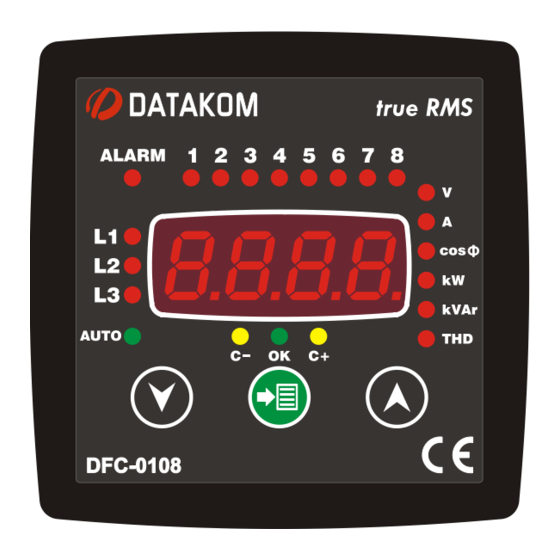
DFC-0108 is a high technology controller
allowing the power factor of the installation to
be stabilized to the requested value by
switching capacitor banks through
contactors. The unit allows also the
visualization of various AC parameters like a
network analyzer.
The unit makes harmonic analysis up to the
31th component. The THD values of all
voltages and currents are available.
Stepping algorithms are selectable between
various types. Thanks to the automatic setup
function, the commissioning and
programming are made easy.
The unit fits into a standard 96x96mm panel
opening.
V-1.0
(10.08.2011)
DESCRIPTION
-1-
Advertisement
Table of Contents

Related Manuals for Datakom DKG-108


Summary of Contents for Datakom DKG-108
- Page 1 DKG-108 User Manual V-1.0 (10.08.2011) DKG-108 POWER FACTOR CONTROLLER 8 BANKS, HARMONIC DISTORTION DISPLAY FEATURES DESCRIPTION Small size DFC-0108 is a high technology controller allowing the power factor of the installation to Cost effective and high performance be stabilized to the requested value by...
- Page 2 DKG-108 User Manual V-1.0 (10.08.2011) SAFETY NOTICE Failure to follow below instructions will result in death or serious injury Electrical equipment should be installed only by qualified specialist. No responsibility is assured by the manufacturer or any of its subsidiaries for any consequences resulting from the non-compliance to these instructions.
-
Page 3: Table Of Contents
DKG-108 User Manual V-1.0 (10.08.2011) Current Transformers must be used for current measurement. No direct connection allowed. TABLE OF CONTENTS Section 1. INSTALLATION 1.1. FRONT / REAR PANELS 1.2. MECHANICAL INSTALLATION 1.3. ELECTRICAL INSTALLATION 1.4. CONNECTION DIAGRAM 2. AUTOMATIC SETUP 3. -
Page 4: Installation
DKG-108 User Manual V-1.0 (10.08.2011) 1. INSTALLATION Before installation: Read the user manual carefully, determine the correct connection diagram. Remove all connectors and mounting brackets from the unit, then pass the unit through the mounting opening. Put mounting brackets and tighten. Do not tighten too much, this can brake the enclosure.Self mating brackets do not require tightening. -
Page 5: Front / Rear Panels
DKG-108 User Manual V-1.0 (10.08.2011) 1.1 FRONT / REAR PANELS 1.2 MECHANICAL INSTALLATION Panel Cutout Required Panel Depth... -
Page 6: Electrical Installation
DKG-108 User Manual V-1.0 (10.08.2011) 1.3 ELECTRICAL INSTALLATION Do not install the unit close to high electromagnetic noise emitting devices like contactors, high current busbars, switchmode power supplies and the like. Although the unit is protected against electromagnetic disturbance, excessive disturbance can affect the operation, measurement precision and data communication quality. -
Page 7: Connection Diagram
DKG-108 User Manual V-1.0 (10.08.2011) 1.4 CONNECTION DIAGRAM... -
Page 8: Automatic Setup
DKG-108 User Manual V-1.0 (10.08.2011) 2. AUTOMATIC SETUP In automatic setup mode, the unit : -automatically detects and corrects reverse connected current transformers. -automatically measures and memorizes capacitor bank ratings. For a successful auto setup, voltage connections must be 3 phased. - Page 9 DKG-108 User Manual V-1.0 (10.08.2011) STEP BY STEP AUTO SETUP PUSHBUTTON OPERATION DISPLAY In order to enter the auto setup mode, power- up the unit with MENU button pressed and hold the button pressed for 10 seconds. The display will show ctrFand the unit will ask the current transformer primary rating.
-
Page 10: Pushbutton Functions
DKG-108 User Manual V-1.0 (10.08.2011) 3. PUSHBUTTON FUNCTIONS Access to programming and measurement displays is achieved through 3 pushbuttons on the front panel. PUSHBUTTON FUNCTION In AUTO mode, acknowledges the displayed alarm. If the same alarm occurs again, it will not appear on the display. -
Page 11: Displays
DKG-108 User Manual V-1.0 (10.08.2011) 4. DISPLAYS Display parameter leds at right describe C+ led shown excessive regulation. the measurement on the display. OK led indicates a balanced system. Current display: If the current Phase indicator leds at left describe the... -
Page 12: Displays In Auto And Manual Modes
DKG-108 User Manual V-1.0 (10.08.2011) 4.1 DISPLAYS IN AUTO AND MANUAL MODES Do not Holding the pushbutton pressed for 5 seconds noise e switches betweenAUTO and MANUAL modes. busbar If AUTO mode is selected with a step output activated Do not... -
Page 13: Stepping Programs
DKG-108 User Manual V-1.0 (10.08.2011) 5. STEPPING PROGRAMS The unit is able to apply various stepping programs. The stepping program is selected through “ProG” parameter. It is advised to use the OPTIMAL program (10). Fastest and the most precise regulation is achieved with this program. -
Page 14: Comparaison Of Legacy And Optimal Programs
DKG-108 User Manual V-1.0 (10.08.2011) 5.1 COMPARAISON OF LEGACY AND OPTIMAL PROGRAMS Step configuration: 1.2.3.4.4.4.4.4 Step type: 3 Phase Basic step rating: 1kVAr Target CosØ= 1.000 Inductive reactive load: 20kVar LEGACY PROGRAM The unit has reached the target cosø in... -
Page 15: Alarms
DKG-108 User Manual V-1.0 (10.08.2011) 6. ALARMS The unit constantly monitors abnormal situations occurring in the system. Every monitored parameter has programmable alarm limits and delay timer. Alarms may be of latching or unlatching types. The automatic operation may be programmed to be aborted or continued. -
Page 16: Programming
DKG-108 User Manual V-1.0 (10.08.2011) 7. PROGRAMMING 7.1 ENTERING AND EXITING PROGRAMMING In order to provide the maximum flexibility to the user, the unit features many programmable parameters. The parameters are recorded in a non-volatile memory and are not affected by power supply failures. -
Page 17: Lamp Test
DKG-108 User Manual V-1.0 (10.08.2011) 7.2 LAMP TEST The unit makes a LAMP TEST when exiting the PROGRAM mode. During lamp test all lights turn on. By pressing the MENU pushbutton, normal operation is resumed. If no pushbutton is pressed for 3 minutes the unit will automatically terminate the PROGRAM mode without lamp test. -
Page 18: Program Parameter List
DKG-108 User Manual V-1.0 (10.08.2011) 7.4 PROGRAM PARAMETER LIST DISPLAY DESCRIPTION STD MAX 9999 PASSWORD ENTRY The user password is required. The password is determined by the program parameter “PASS”. The factory set value is “1”. The password “3282” is always valid. - Page 19 DKG-108 User Manual V-1.0 (10.08.2011) DISPLAY DESCRIPTION STD MAX STEPPING PROGRAM SELECTION This parameter selects betweenLEGACY and OPTIMAL stepping programs. The unit is advised to be operated under OPTIMAL program. Program details are emphasized in chapter 5. 1 sec 20 sec...
- Page 20 DKG-108 User Manual V-1.0 (10.08.2011) DISPLAY DESCRIPTION STD MAX CAPACITOR RATING (CAP1...CAP8) 999.9 kVAr kVAR kVAr This is thecapacitor bank rating, adjusted between 0.1 and 999.9 kVAr. If the parameter“Prog” is set to a value between 1 and 8, then only CAP1 parameter is used.
- Page 21 DKG-108 User Manual V-1.0 (10.08.2011) DISPLAY DESCRIPTION STD MAX 20 % REGULATION LIMIT FOR C-/C+ LEDS This is the difference from the target cosø for C-,OK,C+ leds to turn on. 70 V 220V 9999 V NOMINAL VOLTAGE This is the phase-to-neutral voltage for which bank ratings are defined.
- Page 22 DKG-108 User Manual V-1.0 (10.08.2011) DISPLAY DESCRIPTION STD MAX 3 hour AUTOMATIC TESTING OF hour hour DEFECTIVE BANKS A defective bank is not used in regulation. But if the value of this timer is not zero, then defective banks are activated regularly with this period and tested again.
- Page 23 DKG-108 User Manual V-1.0 (10.08.2011) DISPLAY DESCRIPTION STD MAX 9999 V HIGH VOLTAGE ALARM LIMIT Any phase voltage above this limit will generate a high voltage alarm. If this limit is set to zero then the alarm is not monitored.
- Page 24 DKG-108 User Manual V-1.0 (10.08.2011) DISPLAY DESCRIPTION STD MAX 0 Hz 0 Hz 400 Hz HIGH FREQUENCY ALARM LIMIT If the frequency is above this limit, it will generate a high frequency alarm. If this limit is set to zero then the alarm is not monitored.
- Page 25 DKG-108 User Manual V-1.0 (10.08.2011) DISPLAY DESCRIPTION STD MAX 0 kW 6500 ACTIVE POWER HIGH LIMIT If the active power is above this limit, it will generate an excess kW alarm. If this limit is set to zero then the alarm is not monitored.
- Page 26 DKG-108 User Manual V-1.0 (10.08.2011) DISPLAY DESCRIPTION STD MAX 6500 CAPACITIVE REACTIVE POWER kVAR kVAR kVAR HIGH LIMIT If the reactive power is capacitive and above this limit, it will generate an excess kVAr capacitive alarm. If this limit is set to zero then the alarm is not monitored.
- Page 27 DKG-108 User Manual V-1.0 (10.08.2011) DISPLAY DESCRIPTION STD MAX 0.000 0.000 0.999 CAPACITIVE POWER FACTOR (CosØ) LOW LIMIT If the power factor is capacitive and below this limit, it will generate a low power factor capacitive alarm. If this limit is set to 0.000 then the alarm is not monitored.
- Page 28 DKG-108 User Manual V-1.0 (10.08.2011) DISPLAY DESCRIPTION STD MAX 5000 A OVERCURRENT ALARM LIMIT Any phase current above this limit will generate an overcurrent alarm. If this limit is set to zero then the alarm is not monitored. 0 sec...
- Page 29 DKG-108 User Manual V-1.0 (10.08.2011) DISPLAY DESCRIPTION STD MAX THD(V) HIGH ALARM LIMIT Any phase voltage THD above this limit will generate a high THD(V) alarm. If this limit is set to zero then the alarm is not monitored. 0 sec...
- Page 30 DKG-108 User Manual V-1.0 (10.08.2011) DISPLAY DESCRIPTION STD MAX 99 % THD(I) HIGH ALARM LIMIT Any phase current THD above this limit will generate a high THD(I) alarm. If this limit is set to zero then the alarm is not monitored.
- Page 31 DKG-108 User Manual V-1.0 (10.08.2011) DISPLAY DESCRIPTION STD MAX 80 % CAPACITOR VALUE LOSS ALARM LIMIT If the measured capacitor bank rating is less than the percent defined by this parameter, compared to its nominal value, then a capacitor value loss alarm is given.
- Page 32 DKG-108 User Manual V-1.0 (10.08.2011) DISPLAY DESCRIPTION STD MAX RELAY OUTPUT FUNCTION 0: Regulation OK 1: Regulation not OK 2: Regulation failure 3: kWh tick 4: kVArh tick 5: High voltage alarm 6: Low voltage alarm 7: High frequency alarm...
- Page 33 DKG-108 User Manual V-1.0 (10.08.2011) DISPLAY DESCRIPTION STD MAX PROGRAMMING PASSWORD 9999 The program mode entry password may be selected between 1 and 9999. kW-kVArPULSEFUNCTION The unit is able to give a 100ms pulse for each kWh or kVArh. This parameter selects the condition for this pulse.
-
Page 34: Technical Specifications
2004/108/EC (EMC) EN 61326 (EMC requirements) PACKAGING INFORMATION Pieces per Package: 12 pieces Package Size: 280 x 170 x 215mm (LxWxH) Package Weight: 4.6 kg DATAKOM Electronics Ltd. Tel: +90-216-466 84 60 Fax: +90-216-364 65 65 e-mail: datakom@datakom.com.tr http: www.datakom.com.tr -34-...
Need help?
Do you have a question about the DKG-108 and is the answer not in the manual?
Questions and answers