Table of Contents
Advertisement
Quick Links
Advertisement
Table of Contents

Related Manuals for ensto Arcteq AQ-F3 0 Series


Summary of Contents for ensto Arcteq AQ-F3 0 Series
- Page 1 AQ-F3x0 Feeder protection device Instruction manual...
-
Page 2: Table Of Contents
A A Q Q -F3x0 -F3x0 Instruction manual Version: 2.00 Table of contents 1 Document inf 1 Document informa ormation tion ..............................................4 4 2 Saf 2 Safe e t t y inf y informa ormation tion ................................................6 6 3 Abbr bbre e via viations... - Page 3 A A Q Q -F3x0 -F3x0 Instruction manual Version: 2.00 7 Sy y st stem int em integra egration tion................................................ 132 8 Connections 8 Connections..................................................133 8.1 Block diagrams........................133 8.2 Connection example ......................134 9 Construction and installa 9 Construction and installation tion ....................
- Page 4 A A Q Q -F3x0 -F3x0 Instruction manual Version: 2.00 Disclaimer Please read these instructions carefully before using the equipment or taking any other actions with respect to the equipment. Only trained and qualified persons are allowed to perform installation, operation, service or maintenance of the equipment.
-
Page 5: Document Inf
A A Q Q -F3x0 -F3x0 1 Document information Instruction manual Version: 2.00 1 Document information Table. 1 - 1. History of Revision 1. R R e e vision vision 1.00 1.00 Date November 2010 Changes • The first revision of the manual. R R e e vision vision 1.01... - Page 6 A A Q Q -F3x0 -F3x0 1 Document information Instruction manual Version: 2.00 • Description for trip logic revised. Changes • Description for the common function added. • Description for the line measurements function added. R R e e vision vision 1.07 1.07...
-
Page 7: Saf Y Informa Ormation Tion
A A Q Q -F3x0 -F3x0 2 Safety information Instruction manual Version: 2.00 2 Safety information This document contains important instructions that should be saved for future use. Read the document carefully before installing, operating, servicing, or maintaining this equipment. Please read and follow all the instructions carefully to prevent accidents, injury and damage to property. -
Page 8: Abbr Bbre E Via Viations Tions
A A Q Q -F3x0 -F3x0 3 Abbreviations Instruction manual Version: 2.00 3 Abbreviations A A C C alternating current A A VR automatic voltage regulator circuit breaker CBFP CBFP circuit breaker failure protection CPU U central processing unit C C T T current transformer C C T T S S current transformer supervision... - Page 9 A A Q Q -F3x0 -F3x0 3 Abbreviations Instruction manual Version: 2.00 intelligent electronic device IO IO inputs and outputs L L CD liquid-crystal display light-emitting diode normally closed normally open Network Time Protocol radio frequency R R CA relay characteristic angle root mean square SCAD SCADA A...
-
Page 10: General
A A Q Q -F3x0 -F3x0 4 General Instruction manual Version: 2.00 4 General The AQ-F3x0 feeder protection IED is a member of the AQ-300 product line. The AQ-300 protection product line in respect of hardware and software is a modular device. The hardware modules are assembled and configured according to the application IO requirements and the software determines the available functions. -
Page 11: Ied User Interface Erface
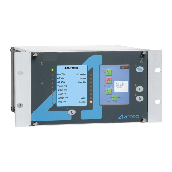
5 IED user interface A A Q Q -F3x0 -F3x0 5.1 Front panel Instruction manual Version: 2.00 5 IED user interface 5.1 Front panel The figure below presents the front panel structure for AQ-300 series units, while the table below the image describes the functions of the front panel's various elements. -
Page 12: Led Assignment
A A Q Q -F3x0 -F3x0 5 IED user interface Instruction manual 5.2 LED assignment Version: 2.00 Function Description The device has four (4) capacitive operational buttons: • "X" (below the LED label) latches and resets the LEDs. Operation • The button with a blue icon (top right) changes the touch screen menus. buttons •... - Page 13 5 IED user interface A A Q Q -F3x0 -F3x0 5.3 Touch screen Instruction manual Version: 2.00 The image below depicts the main screen of the front panel as well as the "ON", "OFF" and "Change screen" buttons. Figure. 5.3 - 2. The main menu and three operation buttons. The t The touch scr ouch screen...
- Page 14 A A Q Q -F3x0 -F3x0 5 IED user interface Instruction manual 5.3 Touch screen Version: 2.00 Figure. 5.3 - 3. Lock status indicator, as displayed in the main menu. The lock sta lock stat t us indic us indica a t t or or shows whether a password is required to unlock the device before parameters or settings can be changed.
- Page 15 5 IED user interface A A Q Q -F3x0 -F3x0 5.3 Touch screen Instruction manual Version: 2.00 Figure. 5.3 - 4. The password input screen. NOTICE! TICE! The lock icon is displayed even when the device has no password! Parameter menu In the parameters menu (below) you can view, set and edit certain parameters within the device.
- Page 16 A A Q Q -F3x0 -F3x0 5 IED user interface Instruction manual 5.3 Touch screen Version: 2.00 Figure. 5.3 - 5. The parameter set menu. The A A ctiv ctiva a t t e but e butt t on on activated the selected parameter set, which the device will now use. Depending on the device's configuration, the "Activate"...
- Page 17 5 IED user interface A A Q Q -F3x0 -F3x0 5.3 Touch screen Instruction manual Version: 2.00 • Floating-point number A number with a decimal point, entered with the number pad. Please note that the pad has the decimal point available only when the value can be entered as a floating-point number! •...
- Page 18 A A Q Q -F3x0 -F3x0 5 IED user interface Instruction manual 5.3 Touch screen Version: 2.00 Online measurement menu The online measurement menu displays real-time data depending on what is connected to the device. When you have selected a specific function block from the online functions list, clicking the V V ie iew w but butt t on takes you to a new window that displays the parameters and their current values.
- Page 19 5 IED user interface A A Q Q -F3x0 -F3x0 5.3 Touch screen Instruction manual Version: 2.00 Figure. 5.3 - 9. Event structure. NOTICE! TICE! The events menu does no not t display the whole event log, only the first few hundred items in the log! System settings menu Figure.
- Page 20 A A Q Q -F3x0 -F3x0 5 IED user interface Instruction manual 5.3 Touch screen Version: 2.00 Table. 5.3 - 5. The system settings. Setting Description System parameters and station bus settings Please contact your local network administrator for further information about these (IP address, settings.
-
Page 21: The Embedded Web Server
5 IED user interface A A Q Q -F3x0 -F3x0 5.4 The embedded web server Instruction manual Version: 2.00 Figure. 5.3 - 11. Turning on Q2. (1) First, we press Q2 on the touch screen to highlight the object. This causes Q2 to start blinking for a short while;... -
Page 22: Ethernet Connections
A A Q Q -F3x0 -F3x0 5 IED user interface Instruction manual 5.4 The embedded web server Version: 2.00 • provide remote or local firmware updgrades • perform administrative tasks. System requirements In order to access the device interface you need a compatible web browser as well as an Ethernet connection. - Page 23 5 IED user interface A A Q Q -F3x0 -F3x0 5.4 The embedded web server Instruction manual Version: 2.00 The diagram below depicts the three (3) different CPU versions and their structures: Figure. 5.4.1 - 12. The three CPU versions. Settings needed for Ethernet connection The AQ-300 devices can only be accessed over Ethernet-based communication protocols.
- Page 24 A A Q Q -F3x0 -F3x0 5 IED user interface Instruction manual 5.4 The embedded web server Version: 2.00 Make sure that your browser does NO NOT T use a proxy server while accessing an AQ-300 device. However, if there is a proxy server in your network, contact the system administrator and have them add an exception.
- Page 25 5 IED user interface A A Q Q -F3x0 -F3x0 5.4 The embedded web server Instruction manual Version: 2.00 Figure. 5.4.1 - 14. Using the RJ45 connection. The crossover cable's pinout has been depicted in the diagram below: Figure. 5.4.1 - 15. The pinout of the crossover cable. Please note that the cable's RJ45 connector can also be connected to an Ethernet switch.
-
Page 26: Getting Started
A A Q Q -F3x0 -F3x0 5 IED user interface Instruction manual 5.4 The embedded web server Version: 2.00 ST-type fiber optic connection The ST-type fiber optic connector of the 100Base-FX Ethernet provides a connection to an Ethernet switch with an identical fiber optic input. When using this connection, all the network's IEDs with client functionalities (e.g. - Page 27 5 IED user interface A A Q Q -F3x0 -F3x0 5.4 The embedded web server Instruction manual Version: 2.00 Figure. 5.4.2 - 17. Web server elements. The menu that is currently selected is highlighted in black (in the image above, the main menu is selected).
-
Page 28: Menu Items
A A Q Q -F3x0 -F3x0 5 IED user interface Instruction manual 5.4 The embedded web server Version: 2.00 5.4.3 Menu items Main menu Figure. 5.4.3 - 18. The main menu and its elements. In the main menu you can control the device's front panel. The image of a touch screen (located on the right) behaves the same way as the actual touch screen. - Page 29 5 IED user interface A A Q Q -F3x0 -F3x0 5.4 The embedded web server Instruction manual Version: 2.00 Parameters menu Figure. 5.4.3 - 19. The parameters menu and its elements. You can view and change various parameters and variables in this menu. You can manage the different parameter sets by resetting, renaming, exporting and importing them.
- Page 30 A A Q Q -F3x0 -F3x0 5 IED user interface Instruction manual 5.4 The embedded web server Version: 2.00 In the "Parameter set" section of the page there are options for managing the parameter sets. The section lists all the available parameter sets, and each can be manipulated with the buttons located on the right of the line.
- Page 31 5 IED user interface A A Q Q -F3x0 -F3x0 5.4 The embedded web server Instruction manual Version: 2.00 Figure. 5.4.3 - 21. The system settings menu. Table. 5.4.3 - 7. The system setting sections and their content. Section name Description If enabled, the device asks you to confirm the saving of new settings by pressing the "I"...
- Page 32 A A Q Q -F3x0 -F3x0 5 IED user interface Instruction manual 5.4 The embedded web server Version: 2.00 Section name Description Contain the parameters to control the LCD panel's behaviour. The light switches off after its set timeout. LCD backlight The "Backlight group"...
- Page 33 5 IED user interface A A Q Q -F3x0 -F3x0 5.4 The embedded web server Instruction manual Version: 2.00 Figure. 5.4.3 - 23. Elements of the events menu. With the R R e e fr fresh esh button you can refresh the list displaying the events, the E E ra rase all e se all ev v ents ents button clears the list on the screen, and the Expor...
- Page 34 A A Q Q -F3x0 -F3x0 5 IED user interface Instruction manual 5.4 The embedded web server Version: 2.00 Figure. 5.4.3 - 25. Disturbance recorder. The "Recorded disturbances" section lists all disturbance records. You can refresh the list with the R R e e fr fresh esh button to display any new disturbance records that have occurred after the page was opened or refreshed last.
- Page 35 5 IED user interface A A Q Q -F3x0 -F3x0 5.4 The embedded web server Instruction manual Version: 2.00 You can set a setpoint by clicking anywhere on the graph, and the positioning the cursor to a desired second point. The preview then displays the timestamp of the first setpoint, and the time difference between the two setpoints.
- Page 36 A A Q Q -F3x0 -F3x0 5 IED user interface Instruction manual 5.4 The embedded web server Version: 2.00 Advanced Figure. 5.4.3 - 29. The Advanced menu. This menu displays the additional, more advanced options. You can set a password request before a user is allowed access to these options.
- Page 37 5 IED user interface A A Q Q -F3x0 -F3x0 5.4 The embedded web server Instruction manual Version: 2.00 The Ge Get r t repor eport t button generates a .zip file that has all of the log files archived together. The files have valuable information and they can help in analyzing errors and malfunctions;...
-
Page 38: Troubleshooting
A A Q Q -F3x0 -F3x0 5 IED user interface Instruction manual 5.4 The embedded web server Version: 2.00 Figure. 5.4.3 - 32. Update manager. 5.4.4 Troubleshooting Some browsers have a tendency to handle and cache various JavaScript function improperly, and this may cause anomalies and errors in the interface. -
Page 39: Soft E Set T Up Up
6 Software setup A A Q Q -F3x0 -F3x0 6.1 Functions included in AQ-F3x0 Instruction manual Version: 2.00 6 Software setup 6.1 Functions included in AQ-F3x0 In this chapter are presented the protection and control functions as well as the monitoring functions. The implemented protection functions are listed in the table below. -
Page 40: Measurements
A A Q Q -F3x0 -F3x0 6 Software setup Instruction manual 6.2 Measurements Version: 2.00 FRC81_1 FRC81_2 df/dt Rate of change of frequency protection FRC81_3 FRC81_4 BRF50MV CBFP 50BF Breaker failure protection DIS21 Z< Distance protection 6.2 Measurements 6.2.1 Current measurement and scaling If the factory configuration includes a current transformer hardware module, the current input function block is automatically configured among the software function blocks. - Page 41 6 Software setup A A Q Q -F3x0 -F3x0 6.2 Measurements Instruction manual Version: 2.00 Figure. 6.2.1 - 33. Example connection. Table. 6.2.1 - 10. Values for the example above. Phase current CT: Ring core CT in Input I0: CT primary 100A I0CT primary 10A CT secondary 5A I0CT secondary 1A...
- Page 42 A A Q Q -F3x0 -F3x0 6 Software setup Instruction manual 6.2 Measurements Version: 2.00 The performed basic calculation results the Fourier basic harmonic magnitude and angle and the true RMS value. These results are processed by subsequent protection function blocks and they are available for on-line displaying as well.
-
Page 43: Voltage Measurement And Scaling
6 Software setup A A Q Q -F3x0 -F3x0 6.2 Measurements Instruction manual Version: 2.00 Measured value Dim. Explanation Angle Ch - I3 degree Vector position of the current in channel IL3 Current Ch - I4 A(secondary) Fourier basic component of the current in channel I4 Angle Ch - I4 degree Vector position of the current in channel I4... - Page 44 A A Q Q -F3x0 -F3x0 6 Software setup Instruction manual 6.2 Measurements Version: 2.00 The connection of the first three VT secondary windings must be set to reflect actual physical connection of the main VTs. The associated parameter is “Connection U1-3“. The selection can be: Ph-N, Ph-Ph or Ph-N-Isolated.
- Page 45 6 Software setup A A Q Q -F3x0 -F3x0 6.2 Measurements Instruction manual Version: 2.00 Figure. 6.2.2 - 36. Phase-to-phase connection. Ph-N Voltage: Residual voltage: Rated Primary U1-3: 20kV Rated Primary U4: 11.54A (=20kV/√3) Range: Type 100 The fourth input is reserved for zero sequence voltage or for a voltage from the other side of the circuit breaker for synchron switching.
- Page 46 A A Q Q -F3x0 -F3x0 6 Software setup Instruction manual 6.2 Measurements Version: 2.00 Parameter name Title Selection range Default VT4_Ch13Nom_EPar_ Connection U1-3 Ph-N, Ph-Ph, Ph-N-Isolated Ph-N Selection of the fourth channel input: phase-to-neutral or phase-to-phase voltage VT4_Ch4Nom_EPar_ Connection U4 Ph-N,Ph-Ph Ph-Ph Definition of the positive direction of the first three input channels, given as normal or inverted...
-
Page 47: Line Measurement
6 Software setup A A Q Q -F3x0 -F3x0 6.2 Measurements Instruction manual Version: 2.00 Measured value Dim. Explanation Angle Ch - U2 degree Vector position of the voltage in channel UL2 Voltage Ch - U3 V(secondary) Fourier basic component of the voltage in channel UL3 Angle Ch - U3 degree Vector position of the voltage in channel UL3... - Page 48 A A Q Q -F3x0 -F3x0 6 Software setup Instruction manual 6.2 Measurements Version: 2.00 The outputs of the line measurement function are • displayed measured values • reports to the SCADA system. NOTICE! TICE! The scaling values are entered as parameter setting for the “Voltage transformer input” function block and for the “Current transformer input”...
- Page 49 6 Software setup A A Q Q -F3x0 -F3x0 6.2 Measurements Instruction manual Version: 2.00 Figure. 6.2.3 - 37. Measured values in a configuration for compensated networks. The available quantities are described in the configuration description documents. Reporting the measured values and the changes For reporting, additional information is needed, which is defined in parameter setting.
- Page 50 A A Q Q -F3x0 -F3x0 6 Software setup Instruction manual 6.2 Measurements Version: 2.00 The selection of the reporting mode items is explained in next chapters. "Amplitude" mode of reporting If the “Amplitude” mode is selected for reporting, a report is generated if the measured value leaves the deadband around the previously reported value.
- Page 51 6 Software setup A A Q Q -F3x0 -F3x0 6.2 Measurements Instruction manual Version: 2.00 Parameter name Title Dim. Step Default Range value for the apparent power MXU_SRange_FPar_ Range value - S 100000 0.01 Deadband value for the current MXU_IDeadB_FPar_ Deadband value - I 2000 Range value for the current...
- Page 52 A A Q Q -F3x0 -F3x0 6 Software setup Instruction manual 6.2 Measurements Version: 2.00 Figure. 6.2.3 - 39. Reporting when Integrated mode is selected. Periodic reporting Periodic reporting is generated independently of the changes of the measured values when the defined time period elapses.
-
Page 53: Protection Functions
6 Software setup A A Q Q -F3x0 -F3x0 6.3 Protection functions Instruction manual Version: 2.00 Parameter name Title Dim. Step Default Deadband value for the phase-to-neutral voltage MXU_UPhDeadB_FPar_ Deadband value - U ph-N 0.01 Range value for the phase-to-neutral voltage MXU_UPhRange_FPar_ Range value - U ph-N 1000... - Page 54 A A Q Q -F3x0 -F3x0 6 Software setup Instruction manual 6.3 Protection functions Version: 2.00 The variables in the image above are: • t (seconds) = theoretical operating time if G>G (without additional time delay) • G = measured peak value or Fourier base harmonic of the phase currents •...
-
Page 55: Residual Instantaneous Overcurrent Protection (I0>; 50N/51N)
6 Software setup A A Q Q -F3x0 -F3x0 6.3 Protection functions Instruction manual Version: 2.00 6.3.2 Residual instantaneous overcurrent protection (I0>; 50N/51N) The residual instantaneous overcurrent protection function operates according to instantaneous characteristics, using the residual current (IN=3Io). The setting value is a parameter, and it can be doubled with dedicated input binary signal. -
Page 56: Three-Phase Time Overcurrent Protection (I>; 50/51)
A A Q Q -F3x0 -F3x0 6 Software setup Instruction manual 6.3 Protection functions Version: 2.00 The algorithm generates a trip command without additional time delay based on the Fourier components of the phase currents or peak values of the phase currents in case if the user set pick-up value is exceeded. - Page 57 6 Software setup A A Q Q -F3x0 -F3x0 6.3 Protection functions Instruction manual Version: 2.00 The function includes a blocking signal input which can be configured by user from either IED internal binary signals or IED binary inputs through the programmable logic. Operating characteristics of the definite time is presented in the figure below.
- Page 58 A A Q Q -F3x0 -F3x0 6 Software setup Instruction manual 6.3 Protection functions Version: 2.00 Table. 6.3.3 - 25. Parameters and operating curve types for the IDMT characteristics. Curve family Characteristics α NI (normally inverse) 0.14 0.02 VI (very inverse) 13.5 EI (extremely inverse) LTI (long time inverse)
- Page 59 6 Software setup A A Q Q -F3x0 -F3x0 6.3 Protection functions Instruction manual Version: 2.00 Figure. 6.3.3 - 47. IEC - VI operating curves with minimum and maximum pick-up settings and TMS settings from 0.05 to 20. Figure. 6.3.3 - 48. IEC - EI operating curves with minimum and maximum pick-up settings and TMS settings from 0.05 to 20.
- Page 60 A A Q Q -F3x0 -F3x0 6 Software setup Instruction manual 6.3 Protection functions Version: 2.00 Figure. 6.3.3 - 49. IEC - LTI operating curves with minimum and maximum pick-up settings and TMS settings from 0.05 to 20. Figure. 6.3.3 - 50. IEEE/ANSI - NI operating curves with minimum and maximum pick-up settings and TMS settings from 0.05 to 20.
- Page 61 6 Software setup A A Q Q -F3x0 -F3x0 6.3 Protection functions Instruction manual Version: 2.00 Figure. 6.3.3 - 51. IEEE/ANSI - MI operating curves with minimum and maximum pick-up settings and TMS settings from 0.05 to 20. Figure. 6.3.3 - 52. IEEE/ANSI - VI operating curves with minimum and maximum pick-up settings and TMS settings from 0.05 to 20.
- Page 62 A A Q Q -F3x0 -F3x0 6 Software setup Instruction manual 6.3 Protection functions Version: 2.00 Figure. 6.3.3 - 53. IEEE/ANSI - EI operating curves with minimum and maximum pick-up settings and TMS settings from 0.05 to 20. Figure. 6.3.3 - 54. IEEE/ANSI - LTI operating curves with minimum and maximum pick-up settings and TMS settings from 0.05 to 20.
- Page 63 6 Software setup A A Q Q -F3x0 -F3x0 6.3 Protection functions Instruction manual Version: 2.00 Figure. 6.3.3 - 55. IEEE/ANSI - LTVI operating curves with minimum and maximum pick-up settings and TMS settings from 0.05 to 20. Figure. 6.3.3 - 56. IEEE/ANSI - LTEI operating curves with minimum and maximum pick-up settings and TMS settings from 0.05 to 20.
- Page 64 A A Q Q -F3x0 -F3x0 6 Software setup Instruction manual 6.3 Protection functions Version: 2.00 Resetting characteristics for the function depends on the selected operating time characteristics. For the IEC type IDMT characteristics the reset time is user settable and for the ANSI/IEEE type characteristics the resetting time follows equation below.
-
Page 65: Residual Time Overcurrent Protection (I0>; 50N/51N)
6 Software setup A A Q Q -F3x0 -F3x0 6.3 Protection functions Instruction manual Version: 2.00 Table. 6.3.3 - 27. Setting parameters of the time overcurrent function. Setting Parameter value Step Default Description / range DefinitTime IEC Inv IEC VeryInv IEC ExtInv IEC LongInv ANSI Inv... - Page 66 A A Q Q -F3x0 -F3x0 6 Software setup Instruction manual 6.3 Protection functions Version: 2.00 The variables in the image above are: • t (seconds) = theoretical operating time if G>G (without additional time delay) • G = measured value of the Fourier base harmonic of the residual current •...
-
Page 67: Three-Phase Directional Overcurrent Protection (Idir>; 67)
6 Software setup A A Q Q -F3x0 -F3x0 6.3 Protection functions Instruction manual Version: 2.00 Table. 6.3.4 - 28. Setting parameters of the residual time overcurrent function. Setting Parameter value / Step Default Description Range DefinitTime IEC Inv IEC VeryInv IEC ExtInv IEC LongInv ANSI Inv... - Page 68 A A Q Q -F3x0 -F3x0 6 Software setup Instruction manual 6.3 Protection functions Version: 2.00 Figure. 6.3.5 - 59. The structure of the directional overcurrent protection algorithm. Based on the measured voltages and currents the function block selects the lowest calculated loop impedance of the six loops (L1L2, L2L3, L3L1, L1N, L2N, L3N).
- Page 69 6 Software setup A A Q Q -F3x0 -F3x0 6.3 Protection functions Instruction manual Version: 2.00 Figure. 6.3.5 - 60. Directional decision characteristics. The voltage must be above 5% of the rated voltage and the current must also be measurable. If the voltages are below 5% of the rated voltage then the algorithm substitutes the small values with the voltage values stored in the memory.
-
Page 70: Residual Directional Overcurrent Protection (I0Dir>; 67N)
A A Q Q -F3x0 -F3x0 6 Software setup Instruction manual 6.3 Protection functions Version: 2.00 Setting value Parameter Step Default Description / range DefinitTime IEC Inv IEC VeryInv IEC ExtInv IEC LongInv ANSI Inv Operating mode selection of the function. Can be disabled, Operation ANSI ModInv DefinitTime... - Page 71 6 Software setup A A Q Q -F3x0 -F3x0 6.3 Protection functions Instruction manual Version: 2.00 Figure. 6.3.6 - 61. The structure of the residual directional overcurrent protection algorithm. The block of the directional decision generates a signal of TRUE value if the UN=3Uo zero sequence voltage and the IN=-3Io current is sufficient for directional decision, and the angle difference between the vectors is within the preset range.
- Page 72 A A Q Q -F3x0 -F3x0 6 Software setup Instruction manual 6.3 Protection functions Version: 2.00 Figure. 6.3.6 - 63. Wattmetric and varmetric operating characteristics. In the in the figure above are presented the characteristics of the wattmetric and varmetric operating principles in forward direction.
-
Page 73: Current Unbalance Protection (60)
6 Software setup A A Q Q -F3x0 -F3x0 6.3 Protection functions Instruction manual Version: 2.00 Setting Parameter value / Step Default Description range DefinitTime IEC Inv IEC VeryInv IEC ExtInv IEC LongInv ANSI Inv ANSI Selection of the function disabled and the timing ModInv Operation DefinitTime... - Page 74 A A Q Q -F3x0 -F3x0 6 Software setup Instruction manual 6.3 Protection functions Version: 2.00 Figure. 6.3.7 - 64. The structure of the current unbalance protection algorithm. The analogue signal processing principal scheme is presented in the figure below. Figure.
-
Page 75: Circuit Breaker Failure Protection (Cbfp; 50Bf/52Bf)
6 Software setup A A Q Q -F3x0 -F3x0 6.3 Protection functions Instruction manual Version: 2.00 Table. 6.3.7 - 31. Setting parameters of the current unbalance function. Setting Parameter value / Step Default Description range Operation Selection for the function enabled or disabled. Start Activated Selection if the function issues either "Start"... - Page 76 A A Q Q -F3x0 -F3x0 6 Software setup Instruction manual 6.3 Protection functions Version: 2.00 Figure. 6.3.8 - 66. Operation logic of the CBFP function. Table. 6.3.8 - 32. Setting parameters of the CBFP function. Setting Parameter value / Step Default Description range...
-
Page 77: Overvoltage Protection (U>; 59)
6 Software setup A A Q Q -F3x0 -F3x0 6.3 Protection functions Instruction manual Version: 2.00 6.3.9 Overvoltage protection (U>; 59) The overvoltage protection function measures three phase to ground voltages. If any of the measured voltages is above the pick-up setting, a start signal is generated for the phases individually. Figure. -
Page 78: Residual Overvoltage Protection (U0>; 59N)
A A Q Q -F3x0 -F3x0 6 Software setup Instruction manual 6.3 Protection functions Version: 2.00 Figure. 6.3.10 - 68. The principal structure of the undervoltage function. The general start signal is set active if the voltage of any of the three measured voltages is below the level defined by pick-up setting value. -
Page 79: Thermal Overload Protection (T>; 49)
6 Software setup A A Q Q -F3x0 -F3x0 6.3 Protection functions Instruction manual Version: 2.00 Figure. 6.3.11 - 69. The principal structure of the residual overvoltage function. The general start signal is set active if the measured residual voltage is above the level defined by pick- up setting value. - Page 80 A A Q Q -F3x0 -F3x0 6 Software setup Instruction manual 6.3 Protection functions Version: 2.00 Figure. 6.3.12 - 70. The principal structure of the thermal overload function. In the figure above is presented the principal structure of the thermal overload function. Theinputs of the function are the maximum of TRMS values of the phase currents, ambienttemperature setting, binary input status signals and setting parameters.
-
Page 81: Overfrequency Protection (F>; 81O)
6 Software setup A A Q Q -F3x0 -F3x0 6.3 Protection functions Instruction manual Version: 2.00 Setting Parameter value / Step Default Description range Rated 60…200 Rated temperature of the protected object. temperature Base Rated ambient temperature of the device related to allowed 0…40 deg 40 deg temperature... -
Page 82: Underfrequency Protection (F<; 81U)
A A Q Q -F3x0 -F3x0 6 Software setup Instruction manual 6.3 Protection functions Version: 2.00 Setting value Parameter Step Default Description / range Start Activated Selection if the function issues either “Start” signal alone or Deactivated signal only Deactivated both “Start”... -
Page 83: Rate-Of-Change Of Frequency Protection (Fd/Ft>/<; 81R)
6 Software setup A A Q Q -F3x0 -F3x0 6.3 Protection functions Instruction manual Version: 2.00 6.3.15 Rate-of-change of frequency protection (fd/ft>/<; 81R) The deviation of the frequency from the rated system frequency indicates unbalance between the generated power and the load demand. If the available generation is small compared to the consumption by the load connected to the power system, then the system frequency is below the rated value. -
Page 84: Distance Protection
A A Q Q -F3x0 -F3x0 6 Software setup Instruction manual 6.3 Protection functions Version: 2.00 Table. 6.3.16 - 40. Setting parameters of the inrush current function. Setting Parameter value / Step Default Description range Current Operating mode selection for the function. Operation can be either Operation Contact Current... - Page 85 6 Software setup A A Q Q -F3x0 -F3x0 6.3 Protection functions Instruction manual Version: 2.00 Detection of power swing condition and out-of-step operation are available. The structure of the distance protection algorithm is described in figure below. Figure. 6.3.17 - 71. Structure of the distance protection. The inputs are: •...
- Page 86 A A Q Q -F3x0 -F3x0 6 Software setup Instruction manual 6.3 Protection functions Version: 2.00 Principle of the impedance calculation The distance protection continuously measures the impedances in the six possible fault loops. The calculation is performed in the phase-to-phase loops based on the line-to-line voltages and the difference of the affected phase currents, while in the phase-to-earth loops the phase voltage is divided by the phase current compounded with the zero sequence current.
- Page 87 6 Software setup A A Q Q -F3x0 -F3x0 6.3 Protection functions Instruction manual Version: 2.00 It can be proven that if the setting value of the complex earth fault compensation factor is correct, the appropriate application of the formulas in the table will always yield the positive sequence impedance between the fault location and the relay location.
- Page 88 A A Q Q -F3x0 -F3x0 6 Software setup Instruction manual 6.3 Protection functions Version: 2.00 = the positive sequence resistance of the line or cable section between the fault location and the relay location = the positive sequence inductance of the line or cable section between the fault location and the relay location L1 = the faulty phase 3io = iL1 + iL2 + iL3 = the sampled value of the zero sequence current of the protected line...
- Page 89 6 Software setup A A Q Q -F3x0 -F3x0 6.3 Protection functions Instruction manual Version: 2.00 The inputs are the sampled values and Fourier components of: • Three phase voltages • Three phase currents • (3Iop) zero sequence current of the parallel line •...
- Page 90 A A Q Q -F3x0 -F3x0 6 Software setup Instruction manual 6.3 Protection functions Version: 2.00 Internal logic of the impedance calculation Figure. 6.3.17 - 74. Impedance calculation internal logic. The decision needs logic parameter settings and, additionally, internal logic signals. The explanation of these signals is as follows: Table.
- Page 91 6 Software setup A A Q Q -F3x0 -F3x0 6.3 Protection functions Instruction manual Version: 2.00 Input status signal Explanation The voltage is suitable for the calculation if the most recent ten sampled values VOLT_OK_HIGH include a sample above the defined limit (35 % of the nominal loop voltage). This status signal is generated within the Z_CAL Z_CALC C module.
- Page 92 A A Q Q -F3x0 -F3x0 6 Software setup Instruction manual 6.3 Protection functions Version: 2.00 The impedance calculation methods The short explanation of the internal logic for the impedance calculation is as follows: Calcula Calculation me tion method Calc(A thod Calc(A) ) If the CURRENT_OK status signal is false, the current is very small, therefore no fault is possible.
- Page 93 6 Software setup A A Q Q -F3x0 -F3x0 6.3 Protection functions Instruction manual Version: 2.00 R = 1 000 500, X = 1 000 500 Calcula Calculation me tion method Calc(G) thod Calc(G) If no directional decision is required, then the decision is based on the absolute value of the impedance (forward fault is supposed) R = abs(R), X = abs(X) Calcula...
- Page 94 A A Q Q -F3x0 -F3x0 6 Software setup Instruction manual 6.3 Protection functions Version: 2.00 The calculated R and X =ϖL co-ordinate values define six points on the complex impedance plane for the six possible measuring loops. These impedances are the positive sequence impedances. The protection compares these points with the Mho characteristics of the distance protection.
- Page 95 6 Software setup A A Q Q -F3x0 -F3x0 6.3 Protection functions Instruction manual Version: 2.00 Figure. 6.3.17 - 77. Polygon characteristics logic. Figure. 6.3.17 - 78. Mho characteristics logic. Table. 6.3.17 - 46. Input impedances for the characteristics logic. Input values Zones Explanation...
- Page 96 A A Q Q -F3x0 -F3x0 6 Software setup Instruction manual 6.3 Protection functions Version: 2.00 Input values Zones Explanation RL3L1+j Calculated impedance in the fault loop L3L1 using parameters of the zones 1…5 XL3L1 individually Table. 6.3.17 - 47. Output signals of the characteristics logic. Output values Zones Explanation...
- Page 97 6 Software setup A A Q Q -F3x0 -F3x0 6.3 Protection functions Instruction manual Version: 2.00 Table. 6.3.17 - 48. Setting parameters of the distance to fault calculation. Parameter Title Dim. Default DIS21_Lgth_FPar_ Line length 1 000 DIS21_LReact_FPar_ Line reactance 0.01 Online measured values of the distance protection function Table.
- Page 98 A A Q Q -F3x0 -F3x0 6 Software setup Instruction manual 6.3 Protection functions Version: 2.00 Measured value Dim. Explanation ZL2L3 = Measured positive sequence impedance in the L2L3 loop RL2L3+j XL2L3 ZL3L1 = Measured positive sequence impedance in the L3L1 loop RL3L1+j XL3L1 Fault location Measured distance to fault...
-
Page 99: Control, Monitoring And Measurements
6 Software setup A A Q Q -F3x0 -F3x0 6.4 Control, monitoring and measurements Instruction manual Version: 2.00 Binary input signal Signal title Explanation DIS21_Z1Blk_GrO_ Block Z1 Blocking of Zone 1 DIS21_Z2Blk_GrO_ Block Z2 Blocking of Zone 2 DIS21_Z3Blk_GrO_ Block Z3 Blocking of Zone 3 DIS21_Z4Blk_GrO_ Block Z4... - Page 100 A A Q Q -F3x0 -F3x0 6 Software setup Instruction manual 6.4 Control, monitoring and measurements Version: 2.00 1. The W 1. The WARNING signal of the de ARNING signal of the device vice The AQ300 series devices have several LED-s on the front panel. The upper left LED indicates the state of the device: •...
- Page 101 6 Software setup A A Q Q -F3x0 -F3x0 6.4 Control, monitoring and measurements Instruction manual Version: 2.00 Figure. 6.4.1 - 82. The function block of the common function block. Table. 6.4.1 - 53. The binary output status signals. Binary output status signal Title Explanation Common_ExtWarning_GrO_...
-
Page 102: Trip Logic (94)
A A Q Q -F3x0 -F3x0 6 Software setup Instruction manual 6.4 Control, monitoring and measurements Version: 2.00 Binary input status signal Title Explanation Common_Remote4_GrI_ Remote 4 Output 4 to indicate the state of group 4 as Remote Fix signal FALSE to be applied in the graphic logic editor, if Common_FixFalse_GrI_ False needed... - Page 103 6 Software setup A A Q Q -F3x0 -F3x0 6.4 Control, monitoring and measurements Instruction manual Version: 2.00 Application example Figure. 6.4.2 - 84. Example picture where two I> TOC51 and I0> TOC51N trip signals are connected to two trip logic function blocks.
-
Page 104: Dead Line Detection (Dld)
A A Q Q -F3x0 -F3x0 6 Software setup Instruction manual 6.4 Control, monitoring and measurements Version: 2.00 Trip contact connections for wirings can be found in Hardware configuration under Rack designer → Preview or in Connection allocations. During the parameter setting phase it should be taken care that the trip logic blocks are activated. The parameters are described in the following table. - Page 105 6 Software setup A A Q Q -F3x0 -F3x0 6.4 Control, monitoring and measurements Instruction manual Version: 2.00 Figure. 6.4.3 - 88. The function block of the dead line detection function. The binary input and output status signals of the dead line detection function are listed in tables below. Table.
-
Page 106: Voltage Transformer Supervision (Vts)
A A Q Q -F3x0 -F3x0 6 Software setup Instruction manual 6.4 Control, monitoring and measurements Version: 2.00 Setting Parameter value/ Step Default Description range Minimum current threshold for detecting the dead line status. If all the Min. 8…100 phase to ground voltages are under the setting "Min. operate voltage" operate 10 % and also all the phase currents are under the "Min. - Page 107 6 Software setup A A Q Q -F3x0 -F3x0 6.4 Control, monitoring and measurements Instruction manual Version: 2.00 Figure. 6.4.4 - 89. Operation logic of the voltage transformer supervision and dead line detection. The voltage transformer supervision logic operates through decision logic presented in the following figure.
-
Page 108: Current Transformer Supervision (Cts)
A A Q Q -F3x0 -F3x0 6 Software setup Instruction manual 6.4 Control, monitoring and measurements Version: 2.00 Figure. 6.4.4 - 91. The function block of the voltage transformer supervision function. The binary input and output status signals of voltage transformer supervision function are listed in tables below. -
Page 109: Synchrocheck (Dv/Da/Df; 25)
6 Software setup A A Q Q -F3x0 -F3x0 6.4 Control, monitoring and measurements Instruction manual Version: 2.00 The function can be disabled by parameter setting, and by an input signal programmed by the user. The failure signal is generated after the defined time delay. The function block of the current transformer supervision function is shown in figure bellow. - Page 110 A A Q Q -F3x0 -F3x0 6 Software setup Instruction manual 6.4 Control, monitoring and measurements Version: 2.00 The conditions for safe closing are as follows: • The difference of the voltage magnitudes is below the set limit. • The difference of the frequencies is below the set limit. •...
- Page 111 6 Software setup A A Q Q -F3x0 -F3x0 6.4 Control, monitoring and measurements Instruction manual Version: 2.00 Figure. 6.4.6 - 93. Operation logic of the synchrocheck function. The synchro check/synchro switch function contains two kinds of software blocks: • SYN25_Com = a common block for manual switching and automatic switching. •...
- Page 112 A A Q Q -F3x0 -F3x0 6 Software setup Instruction manual 6.4 Control, monitoring and measurements Version: 2.00 If the active bus section changes the function is dynamically blocked for 1000ms and no release signal or switching command is generated. The processed line voltage is selected based on the preset parameter (Voltage select).
- Page 113 6 Software setup A A Q Q -F3x0 -F3x0 6.4 Control, monitoring and measurements Instruction manual Version: 2.00 If the conditions are fulfilled for at least 45 ms, then the function generates a release output signal (Release Auto/Manual).If the conditions for synchro check operation are not fulfilled and a close request is received as the input signal (SySwitch Auto/Manual), then synchro switching is attempted.
- Page 114 A A Q Q -F3x0 -F3x0 6 Software setup Instruction manual 6.4 Control, monitoring and measurements Version: 2.00 Binary status signal Title Explanation Cancel SYN25_CancelM_GrO_ Signal to interrupt (cancel) the manual switching procedure. Manual Table. 6.4.6 - 65. The binary output signals. Binary status signal Title Explanation...
- Page 115 6 Software setup A A Q Q -F3x0 -F3x0 6.4 Control, monitoring and measurements Instruction manual Version: 2.00 Setting Parameter value/ Step Default Description range Breaker operating time at closing. This parameter is used for the synchroswitch closing command compensation and it Breaker Time 0…500 ms 80 ms...
-
Page 116: Auto-Reclosing (Mv) (79)
A A Q Q -F3x0 -F3x0 6 Software setup Instruction manual 6.4 Control, monitoring and measurements Version: 2.00 Setting Parameter value/ Step Default Description range Manual synchroswitching selection. Selection may be enabled SynSW Man "On" or disabled "Off". Deadbus Energizing mode of manual synchroswitching. Selections LiveLine Energizing DeadBus... - Page 117 6 Software setup A A Q Q -F3x0 -F3x0 6.4 Control, monitoring and measurements Instruction manual Version: 2.00 • After a pickup of the protection function, a timer starts to measure the “ “ A A ction time ction time” ” (the duration depends on parameter setting (Action time)).
- Page 118 A A Q Q -F3x0 -F3x0 6 Software setup Instruction manual 6.4 Control, monitoring and measurements Version: 2.00 The automatic reclosing function is prepared to generate three-phase trip commands only. The applied dead time setting depends on the first detected fault type indicated by the input signal (EarthFaultTrip NoPhF).
- Page 119 6 Software setup A A Q Q -F3x0 -F3x0 6.4 Control, monitoring and measurements Instruction manual Version: 2.00 • If no “CB ready” signal is received at the intended time of reclosing command. • The dead time is prolonged further then the preset parameter value (DeadTime Max.Delay). •...
- Page 120 A A Q Q -F3x0 -F3x0 6 Software setup Instruction manual 6.4 Control, monitoring and measurements Version: 2.00 Setting value/ Parameter Step Default Description range Close Pulse duration setting for the CLOSE command from the IED Command 10…10 000 ms 100 ms to circuit breaker.
-
Page 121: Switch-On-To-Fault
6 Software setup A A Q Q -F3x0 -F3x0 6.4 Control, monitoring and measurements Instruction manual Version: 2.00 Setting value/ Parameter Step Default Description range Accelerate Enabled Disabled Acceleration of the 3 reclosing cycle trip command. 3. Trip Disabled Accelerate Enabled Disabled Acceleration of the 4... -
Page 122: Voltage Variation (Voltage Sag And Swell)
A A Q Q -F3x0 -F3x0 6 Software setup Instruction manual 6.4 Control, monitoring and measurements Version: 2.00 • CBClose Manual close command to the circuit breaker. • DeadLine Dead line condition detected; this is usually the output signal of the DLD (dead line detection) function block. - Page 123 6 Software setup A A Q Q -F3x0 -F3x0 6.4 Control, monitoring and measurements Instruction manual Version: 2.00 • Voltage swell, when the RMS value of the measured voltage is above a level defined by a dedicated parameter. For the evaluation, the duration of the voltage swell should be between a minimum and a maximum time value defined by parameters.
- Page 124 A A Q Q -F3x0 -F3x0 6 Software setup Instruction manual 6.4 Control, monitoring and measurements Version: 2.00 NOTICE! TICE! if all three phase-to-phase voltages do not fall below the specified “Interruption Limit” value, then the event is classified as “sag” but the reported minimum value is set to zero. The sag and swell detection algorithm measures the duration of the short-time voltage variation.
-
Page 125: Disturbance Recorder
6 Software setup A A Q Q -F3x0 -F3x0 6.4 Control, monitoring and measurements Instruction manual Version: 2.00 Figure. 6.4.9 - 103. Example sag and swell. 6.4.10 Disturbance recorder The disturbance recorder function can record analog signals and binary status signals. These signals are user configurable. -
Page 126: Event Recorder
A A Q Q -F3x0 -F3x0 6 Software setup Instruction manual 6.4 Control, monitoring and measurements Version: 2.00 Figure. 6.4.10 - 104. The function block of the disturbance recorder function. The binary input and output status signals of the dead line detection function are listed intables below. Table. - Page 127 6 Software setup A A Q Q -F3x0 -F3x0 6.4 Control, monitoring and measurements Instruction manual Version: 2.00 Trip L1 Trip command in phase L1 Trip L2 Trip command in phase L2 Trip L3 Trip command in phase L3 General Trip General trip command R R esid esidual instantaneous o...
- Page 128 A A Q Q -F3x0 -F3x0 6 Software setup Instruction manual 6.4 Control, monitoring and measurements Version: 2.00 Definit finite time o e time ov v er erv v olta oltage pr ge pro o t t ection function (T ection function (TO O V59) V59) Low Start L1...
- Page 129 6 Software setup A A Q Q -F3x0 -F3x0 6.4 Control, monitoring and measurements Instruction manual Version: 2.00 Rat t e e -of-change of fr -of-change of frequency pr equency pro o t t ection function (FR ection function (FRC81) C81) Low General Start Low setting stage general start signal...
- Page 130 A A Q Q -F3x0 -F3x0 6 Software setup Instruction manual 6.4 Control, monitoring and measurements Version: 2.00 Frequency Frequency violation CB1P CB1Pol ol Status value Status of the circuit breaker Enable Close Close command is enabled Enable Open Open command is enabled Local Local mode of operation Operation counter...
-
Page 131: Measured Values
6 Software setup A A Q Q -F3x0 -F3x0 6.4 Control, monitoring and measurements Instruction manual Version: 2.00 6.4.12 Measured values The measured values can be checked on the touch-screen of the device in the “On-line functions” page, or using an Internet browser of a connected computer. The displayed values are secondary voltages and currents, except the block “Line measurement”. -
Page 132: Status Monitoring For Switching Devices
A A Q Q -F3x0 -F3x0 6 Software setup Instruction manual 6.4 Control, monitoring and measurements Version: 2.00 Analog value Explanation Line thermal pr Line thermal pro o t t ection ection Calc. Temperature Calculated line temperature S S ynchr ynchrocheck ocheck Voltage Diff... -
Page 133: Arcteq Relays Ltd
7 System integration A A Q Q -F3x0 -F3x0 6.4 Control, monitoring and measurements Instruction manual Version: 2.00 7 System integration The AQ F3x0 contains two ports for communicating to upper level supervisory system and one for process bus communication. The physical media or the ports can be either serial fiber optic or RJ 45 or Ethernet fiber optic. -
Page 134: Block Diagrams
A A Q Q -F3x0 -F3x0 8 Connections Instruction manual 8.1 Block diagrams Version: 2.00 8 Connections 8.1 Block diagrams NOTICE! TICE! The structure of both AQ-F350 (the half-rack version) and AQ-F390 (the full rack version) is the same, except AQ-F390 has more option card slots available. Block diagram of AQ-F350 with minimum connections Figure. -
Page 135: Connection Example
8 Connections A A Q Q -F3x0 -F3x0 8.2 Connection example Instruction manual Version: 2.00 Block diagram of AQ-F350 with all options Figure. 8.1 - 106. Block diagram of AQ-F350 with all options installed. O12+ 1101 PS+ 1030 DI 1 DI 2 AQ-F350 DI 3... - Page 136 A A Q Q -F3x0 -F3x0 8 Connections Instruction manual 8.2 Connection example Version: 2.00 Figure. 8.2 - 107. Connection example of AQ-F350 feeder protection IED. © Arcteq Relays Ltd IM00070...
-
Page 137: Construction And Installation Tion
9 Construction and installation A A Q Q -F3x0 -F3x0 9.1 Construction Instruction manual Version: 2.00 9 Construction and installation 9.1 Construction The Arcteq AQ-F3x0 feeder protection IED consists of hardware modules. Due to its modular structure the optional positions for the slots can be user defined in the ordering of the IED to include I/O modules and other types of additional modules. -
Page 138: Cpu Module
A A Q Q -F3x0 -F3x0 9 Construction and installation Instruction manual 9.2 CPU module Version: 2.00 Position Module identifier Explanation Signaling output module, 8 output contacts (7 NO + 1 R8+ 00 Spare — Spare — CPU+ 1201 Processor and communication module Figure. -
Page 139: Power Supply Module
9 Construction and installation A A Q Q -F3x0 -F3x0 9.3 Power supply module Instruction manual Version: 2.00 Each processor has its own operative memory such as SDRAM and flash memories for configuration, parameter and firmware storage. CDSP’s operating system (uClinux) utilizes a robust JFFS flash file system, which enables fail-safe operation and the storage of disturbance record files, configuration and parameters. -
Page 140: Binary Input Module(S)
A A Q Q -F3x0 -F3x0 9 Construction and installation Instruction manual 9.4 Binary input module(s) Version: 2.00 • Passive heat sink cooling. • Early power failure indication signals to the CPU the possibility of power outage, thus the CPU has enough time to save the necessary data to non-volatile memory. -
Page 141: Binary Output Module(S)
9 Construction and installation A A Q Q -F3x0 -F3x0 9.5 Binary output module(s) Instruction manual Version: 2.00 9.5 Binary output module(s) Figure. 9.5 - 112. The binary output module R8+ 80. The signaling output modules can be ordered as 8 relay outputs with dry contacts. The binary output modules are: •... -
Page 142: Tripping Module
A A Q Q -F3x0 -F3x0 9 Construction and installation Instruction manual 9.6 Tripping module Version: 2.00 9.6 Tripping module Figure. 9.6 - 113. The tripping module TRIP+ 2101. The tripping module applies direct control of a circuit breaker. The module provides fast operation and is rated for heavy duty controlling. -
Page 143: Voltage Measurement Module
9 Construction and installation A A Q Q -F3x0 -F3x0 9.7 Voltage measurement module Instruction manual Version: 2.00 9.7 Voltage measurement module Figure. 9.7 - 114. The voltage measurement module VT+ 2211. For voltage related functions (over- /under -voltage, directional functions, distance function,power functions) or disturbance recorder functionality this module is needed. -
Page 144: Current Measurement Module
A A Q Q -F3x0 -F3x0 9 Construction and installation Instruction manual 9.8 Current measurement module Version: 2.00 9.8 Current measurement module Figure. 9.8 - 115. Connector allocation of the current measurement module. Current measurement module is used for measuring current transformer output current. Module includes three phase current inputs and one zero sequence current input. -
Page 145: Installation And Dimensions
9 Construction and installation A A Q Q -F3x0 -F3x0 9.9 Installation and dimensions Instruction manual Version: 2.00 9.9 Installation and dimensions Figure. 9.9 - 116. Dimensions of AQ-x35x IED. © Arcteq Relays Ltd IM00070... - Page 146 A A Q Q -F3x0 -F3x0 9 Construction and installation Instruction manual 9.9 Installation and dimensions Version: 2.00 Figure. 9.9 - 117. Panel cut-out and spacing of AQ-x35x IED. Figure. 9.9 - 118. Dimensions of AQ-x39x IED. © Arcteq Relays Ltd IM00070...
- Page 147 9 Construction and installation A A Q Q -F3x0 -F3x0 9.9 Installation and dimensions Instruction manual Version: 2.00 Figure. 9.9 - 119. Panel cut-out and spacing of AQ-x39x IED. © Arcteq Relays Ltd IM00070...
-
Page 148: Technic Echnical Da Al Data Ta
A A Q Q -F3x0 -F3x0 10 Technical data Instruction manual 10.1 Protection functions Version: 2.00 10 Technical data 10.1 Protection functions Breaker failure protection function CBFP, (50BF) Current inaccuracy <2 % Re-trip time Approx. 15ms Operation time inaccuracy + 5ms Current reset time 20ms Current unbalance protection function (60) - Page 149 10 Technical data A A Q Q -F3x0 -F3x0 10.1 Protection functions Instruction manual Version: 2.00 Pickup time 25 – 30ms Residual instantaneous overcurrent protection I0> (50N) Operating characteristic Instantaneous Picku-up current inaccuracy <2% Reset ratio 0.95 Operate time at 2*In <15 ms Peak value calculation <25 ms...
- Page 150 A A Q Q -F3x0 -F3x0 10 Technical data Instruction manual 10.1 Protection functions Version: 2.00 Operation time inaccuracy ±5% or ±15ms Reset ratio 0.95 Minimum operating time with IDMT 35ms Reset time Approx 35ms Transient overreach Pickup time 25 – 30ms Angular inaccuracy <3°...
- Page 151 10 Technical data A A Q Q -F3x0 -F3x0 10.1 Protection functions Instruction manual Version: 2.00 Underfrequency protection function f< (81U) Operating range 40 - 70 Hz Operating range inaccuracy 30 mHz Effective range inaccuracy 2 mHz Minimum operating time 140 ms Operation time inaccuracy +10 ms...
-
Page 152: Control Functions
A A Q Q -F3x0 -F3x0 10 Technical data Instruction manual 10.2 Control functions Version: 2.00 Reset ratio Inrush current detection function INR2, (68) Current inaccuracy <2 % Reset ratio 0,95 Operating time Approx. 20 ms 10.2 Control functions Autoreclosing function, (79) Operating time inaccuracy ±1% of setting value or ±30ms Switch on to fault logic... -
Page 153: Hardware
10 Technical data A A Q Q -F3x0 -F3x0 10.4 Hardware Instruction manual Version: 2.00 Voltage transformer supervision function VTS Pick-up voltage inaccuracy Operation time inaccuracy <20 ms Reset ratio 0.95 Voltage variation (sag and swell) Voltage measurement inaccuracy ±1 % of Un Timer inaccuracy ±2 % of setting value or ±... - Page 154 A A Q Q -F3x0 -F3x0 10 Technical data Instruction manual 10.4 Hardware Version: 2.00 Current measurement range 0-50xIn 0.01 VA with 1A rated current Power consumption at rated current 0.25 VA with 5A rated current Phase angle accuracy at Ix ≥ 10% ± 1 digit ≤...
-
Page 155: Tests And Environmental Conditions
10 Technical data A A Q Q -F3x0 -F3x0 10.5 Tests and environmental conditions Instruction manual Version: 2.00 High speed trip module Rated voltage Un 110/220VDC Max. withstand voltage 242V DC Number of outputs per module Continuous carry Making capacity 30A (0.5s) Breaking capacity 4A (L/R=40ms, 220Vdc) - Page 156 A A Q Q -F3x0 -F3x0 10 Technical data Instruction manual 10.5 Tests and environmental conditions Version: 2.00 Casing and package Protection degree (front) IP 54 (with optional cover) 5kg net (AQ-x35x devices) 6kg net (AQ-x39x devices) Weight 6kg with package (AQ-x35x devices) 7kg with package (AQ-x39x devices) Environmental conditions Specified ambient service temp.
-
Page 157: Ordering Inf Dering Informa Ormation Tion
11 Ordering information A A Q Q -F3x0 -F3x0 10.5 Tests and environmental conditions Instruction manual Version: 2.00 11 Ordering information Visit https://configurator.arcteq.fi/ to build a hardware configuration, define an ordering code and get a module layout image. © Arcteq Relays Ltd IM00070... -
Page 158: Contact And R Ence Informa Ormation Tion
A A Q Q -F3x0 -F3x0 12 Contact and reference information Instruction manual 10.5 Tests and environmental conditions Version: 2.00 12 Contact and reference information Manufacturer Arcteq Relays Ltd. Visiting and postal address Kvartsikatu 2 A 1 65300 Vaasa, Finland Contacts Phone: +358 10 3221 370...
Need help?
Do you have a question about the Arcteq AQ-F3 0 Series and is the answer not in the manual?
Questions and answers