Table of Contents
Advertisement
Quick Links
Advertisement
Table of Contents

Related Manuals for ensto Arcteq AQ-M257


Summary of Contents for ensto Arcteq AQ-M257
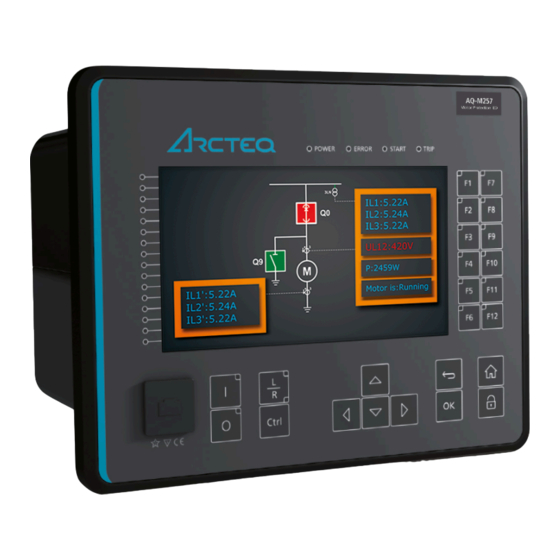
- Page 1 AQ-M257 Motor protection device Instruction manual...
-
Page 2: Table Of Contents
A A Q Q -M257 -M257 Instruction manual Version: 2.11 Table of contents 1 Document inf 1 Document informa ormation tion ..............................................6 6 1.1 Version 2 revision notes ......................6 1.2 Version 1 revision notes ......................9 1.3 Safety information ........................ 10 1.4 Abbreviations........................ - Page 3 A A Q Q -M257 -M257 Instruction manual Version: 2.11 4.5 Control functions ....................... 329 4.5.1 Common signals...................... 329 4.5.2 Setting group selection .................... 330 4.5.3 Object control and monitoring.................. 338 4.5.4 Indicator object monitoring ..................349 4.5.5 Milliampere output control ..................350 4.5.6 Programmable control switch ..................
- Page 4 A A Q Q -M257 -M257 Instruction manual Version: 2.11 5.3.1 Single system ......................472 5.3.2 Controller redundancy ..................... 472 5.3.3 Power rectifier redundancy ..................472 5.4 Others ..........................473 5.4.1 Diagnostics ......................473 5.4.2 Real-time trending ....................473 6 Communic 6 Communica a tion tion........................
- Page 5 A A Q Q -M257 -M257 Instruction manual Version: 2.11 9.1.2.3 CPU digital inputs ..................542 9.1.2.4 CPU digital outputs..................542 9.1.3 Option cards ......................543 9.1.3.1 Digital input module ..................543 9.1.3.2 Digital output module.................. 544 9.1.3.3 Point sensor arc protection module............. 545 9.1.3.4 Milliampere output module (mA out &...
- Page 6 A A Q Q -M257 -M257 Instruction manual Version: 2.11 Disclaimer Please read these instructions carefully before using the equipment or taking any other actions with respect to the equipment. Only trained and qualified persons are allowed to perform installation, operation, service or maintenance of the equipment.
-
Page 7: Document Inf
A A Q Q -M257 -M257 1 Document information Instruction manual Version: 2.11 1 Document information 1.1 Version 2 revision notes Table. 1.1 - 1. Version 2 revision notes Revision 2.00 Date 6.6.2019 - New more consistent look. - Improved descriptions generally in many chapters. - Improved readability of a lot of drawings and images. - Page 8 A A Q Q -M257 -M257 1 Document information Instruction manual Version: 2.11 - Terminology consistency improved (e.g. binary inputs are now always called digital inputs). - Tech data modified to be more informative about what type of measurement inputs are used (phase currents/voltages, residual currents/voltages), what component of that measurement is available (RMS, TRMS, peak-to-peak) and possible calculated measurement values (powers, impedances, angles etc.).
- Page 9 A A Q Q -M257 -M257 1 Document information Instruction manual Version: 2.11 - Fixed phase current measurement continuous thermal withstand from 30A to 20A. - Fixed lots of timing errors written to registers table. "Prefault" is -200 ms from Start event, Changes "Pretrigger"...
-
Page 10: Version 1 Revision Notes
A A Q Q -M257 -M257 1 Document information Instruction manual Version: 2.11 Date 14.3.2023 - Updated the Arcteq logo on the cover page and refined the manual's visual look. - Added the "Safety information" chapter and changed the notes throughout the document accordingly. -
Page 11: Safety Information
A A Q Q -M257 -M257 1 Document information Instruction manual Version: 2.11 • Measurement value recorder description added. • ZCT connection added to the current measurement description. • Internal harmonics blocking added to the I>, I0>, and I0dir> function descriptions. •... -
Page 12: Abbreviations
A A Q Q -M257 -M257 1 Document information Instruction manual Version: 2.11 1.4 Abbreviations AI – Analog input AR – Auto-recloser ASDU – Application service data unit AVR – Automatic voltage regulator BCD – Binary-coded decimal CB – Circuit breaker CBFP –... - Page 13 A A Q Q -M257 -M257 1 Document information Instruction manual Version: 2.11 I/O – Input and output IRIG-B – Inter-range instruction group, timecode B LCD – Liquid-crystal display LED – Light emitting diode LV – Low voltage NC – Normally closed NO –...
-
Page 14: General
A A Q Q -M257 -M257 2 General Instruction manual Version: 2.11 2 General The AQ-M257 motor protection device is a member of the AQ 250 product line. The hardware and software are modular: the hardware modules are assembled and configured according to the application's I/O requirements and the software determines the available functions. -
Page 15: Device User Int Vice User Interface Erface
A A Q Q -M257 -M257 3 Device user interface Instruction manual Version: 2.11 3 Device user interface 3.1 Panel structure The user interface section of an AQ 200 or AQ 250 series device is divided into two user interface sections: one for the hardware and the other for the software. -
Page 16: Configuring User Levels And Their Passwords
A A Q Q -M257 -M257 3 Device user interface Instruction manual Version: 2.11 When the unit is powered on, the green "Power" LED is lit. When the red "Error" LED is lit, the device has an internal (hardware or software) error that affects the operation of the unit. The activation of the yellow "Start"... - Page 17 A A Q Q -M257 -M257 3 Device user interface Instruction manual Version: 2.11 You can set a new password for a user level by selecting the key icon next to the user level's name. After this you can lock the user level by pressing the R R e e t t urn urn key while the lock is selected.
-
Page 18: Functions Unctions
A A Q Q -M257 -M257 4 Functions Instruction manual Version: 2.11 4 Functions 4.1 Functions included in AQ-M257 The AQ-M257 motor protection device includes the following functions as well as the number of stages for those functions. Table. 4.1 - 3. Protection functions of AQ-M257. F F unction unction packa... - Page 19 A A Q Q -M257 -M257 4 Functions Instruction manual Version: 2.11 ROCOF df/dt>/< (1...8) Rate-of-change of frequency I2> Negative sequence overcurrent/ I2>> 46/46R/ CUB (4) phase current reversal/ X X X I2>>> current unbalance protection I2>>>> U1/U2>/< U1/U2>>/<< 47/27P/ VUB (4) Sequence voltage protection X X X...
-
Page 20: Measurements
A A Q Q -M257 -M257 4 Functions Instruction manual Version: 2.11 50Arc/ ARC (1) IArc>/I0Arc> Arc fault protection (optional) X X X 50NArc Table. 4.1 - 4. Control functions of AQ-M257. F F unction unction packa package Name ( Name (number number ANSI... - Page 21 A A Q Q -M257 -M257 4 Functions Instruction manual Version: 2.11 Figure. 4.2.1 - 2. Current measurement terminology. P P RI: RI: The primary current, i.e. the current which flows in the primary circuit and through the primary side of the current transformer.
- Page 22 A A Q Q -M257 -M257 4 Functions Instruction manual Version: 2.11 The device calculates the scaling factors based on the set values of the CT primary, the CT secondary and the nominal current. The device measures the secondary current, the current output from the current transformer installed into application's primary circuit.
- Page 23 A A Q Q -M257 -M257 4 Functions Instruction manual Version: 2.11 Figure. 4.2.1 - 4. Connections (application 1). Because of the direction of the CTs and because the CTs' P1/S1 side is always wired to the modules's odd inputs, the "Differential calculation mode" setting has to be set to "Subtract" ( Protection → TrafoModule →...
- Page 24 A A Q Q -M257 -M257 4 Functions Instruction manual Version: 2.11 Table. 4.2.1 - 6. Initial data. High-v h-volta oltage side C ge side CT T : : L L o o w w -v -volta oltage side C ge side CT T : : R R ing cor ing core C...
- Page 25 A A Q Q -M257 -M257 4 Functions Instruction manual Version: 2.11 The secondary nominal current (in amperes) is the result of multiplying the per unit value with the phase CT secondary side current. This current can be used when the unit is commissioned and when the directions of CTs are checked.
- Page 26 A A Q Q -M257 -M257 4 Functions Instruction manual Version: 2.11 Figure. 4.2.1 - 8. Connections (application 2). Because of the direction of the CTs and because the CTs' P1/S1 side is always wired to the modules's odd inputs, the "Differential calculation mode" has to be set to "Add" ( Protection → TrafoModule → Idx> [87T,87N] →...
- Page 27 A A Q Q -M257 -M257 4 Functions Instruction manual Version: 2.11 Table. 4.2.1 - 7. Initial data. Machine nominal power: 153 MVA Machine high voltage side nominal amplitude: 132 kV Machine low voltage side nominal amplitude: 15 kV High v h volta oltage side C ge side CT T : :...
- Page 28 A A Q Q -M257 -M257 4 Functions Instruction manual Version: 2.11 Settings Table. 4.2.1 - 8. Settings of the Phase CT scaling. Name Unit Range Step Default Description The selection of the reference used in the device's per-unit system scaling. Either the set phase current CT •...
- Page 29 A A Q Q -M257 -M257 4 Functions Instruction manual Version: 2.11 Name Unit Range Step Default Description A feedback value; the scaling factor Ipu scaling primary for the primary current's per- unit value. A feedback value; the scaling factor Ipu scaling secondary for the secondary current's per- unit value.
- Page 30 A A Q Q -M257 -M257 4 Functions Instruction manual Version: 2.11 Name Unit Range Step Description Phase current ILx TRMS 0.000…1 0.001 The TRMS current (inc. harmonics up to 31 ) measurement × In ("Pha.curr.ILx 250.000 (in p.u.) from each of the phase current channels. TRMS") Peak-to-peak The peak-to-peak current measurement (in p.u.) from each of...
- Page 31 A A Q Q -M257 -M257 4 Functions Instruction manual Version: 2.11 Name Unit Range Step Description Phase current I0x TRMS 0.000…1 The TRMS current (inc. harmonics up to 31 ) measurement × In 0.001 ("Res.curr.I0x 250.000 (in p.u.) from the residual current channel I01 or I02. TRMS") Peak-to-peak The peak-to-peak current measurement (in p.u.) from the...
- Page 32 A A Q Q -M257 -M257 4 Functions Instruction manual Version: 2.11 Table. 4.2.1 - 19. Per-unit sequence current measurements. Name Unit Range Step Description Positive sequence current 0.00…1 The measurement (in p.u.) from the calculated positive × In 0.001 ("Positive sequence 250.0 sequence current.
-
Page 33: Voltage Measurement And Scaling
A A Q Q -M257 -M257 4 Functions Instruction manual Version: 2.11 Table. 4.2.1 - 22. Sequence phase angle measurements. Name Unit Range Step Description Positive sequence current angle The calculated positive sequence current 0.000…360.0 0.001 ("Positive sequence curr.angle") angle. Negative sequence current angle The calculated negative sequence current... - Page 34 A A Q Q -M257 -M257 4 Functions Instruction manual Version: 2.11 Figure. 4.2.2 - 9. Voltage measurement terminology P P RI: RI: The primary voltage, i.e. the voltage in the primary circuit which is connected to the primary side of the voltage transformer.
- Page 35 A A Q Q -M257 -M257 4 Functions Instruction manual Version: 2.11 Figure. 4.2.2 - 10. Connections. The following table presents the initial data of the connection. Table. 4.2.2 - 24. Initial data. P P ha hase v se volta oltage V ge VT T Z Z er ero sequence v...
- Page 36 A A Q Q -M257 -M257 4 Functions Instruction manual Version: 2.11 Figure. 4.2.2 - 11. Example connections for voltage line-to-line measurement. If only two line-to-line voltages are measured, the third one (U ) is calculated based on the U vectors.
- Page 37 A A Q Q -M257 -M257 4 Functions Instruction manual Version: 2.11 The image collection below presents the device's behavior when nominal voltage is injected into the device via secondary test equipment. The measurement mode is 3LN+U4 which means that the device is measuring line-to-neutral voltages.
- Page 38 A A Q Q -M257 -M257 4 Functions Instruction manual Version: 2.11 Problem Check / Resolution The voltages are connected to the measurement module but the order or polarity of The measured one or all phases is incorrect. In device settings, go to Measurement → Phasors and voltage amplitudes are check the "System voltage vectors"...
- Page 39 A A Q Q -M257 -M257 4 Functions Instruction manual Version: 2.11 Name Range Step Default Description Defines how the secondary voltage is scaled to the primary. "Broken Delta" is the most common mode. Does not affect how protection operates, it only affects the displayed primary voltages.
- Page 40 A A Q Q -M257 -M257 4 Functions Instruction manual Version: 2.11 Name Range Step Default Description The selection of the fourth voltage measurement channel's (U4) polarity (direction). The default setting is for the U4 Polarity positive voltage to flow from connector 7 to connector 8, with the secondary voltage's starpoint pointing towards the line.
- Page 41 A A Q Q -M257 -M257 4 Functions Instruction manual Version: 2.11 Table. 4.2.2 - 28. Secondary voltage measurements. Name Range Step Description Secondary The secondary voltage measurement fundamental frequency voltage Ux 0.00…500.00V 0.01V component from each of the voltage channels. ("Ux Volt sec") Secondary voltage Ux...
- Page 42 A A Q Q -M257 -M257 4 Functions Instruction manual Version: 2.11 Table. 4.2.2 - 32. Secondary sequence voltage measurements. Name Range Step Description Secondary positive 0.00…4 The secondary measurement from the calculated positive sequence voltage 0.01V 800.00V sequence voltage. ("Pos.seq.Volt.sec") Secondary negative 0.00…4...
- Page 43 A A Q Q -M257 -M257 4 Functions Instruction manual Version: 2.11 Name Range Step Description System voltage magnitude 0.00…1 The primary line-to-neutral UL1 voltage fundamental frequency component 0.01V (measured or calculated). You can also select the row where the unit for this is ("System 000.00V volt UL1...
- Page 44 A A Q Q -M257 -M257 4 Functions Instruction manual Version: 2.11 Name Range Step Description System voltage angle UL23 0.00…360.00° 0.01° The primary line-to-line angle UL23 (measured or calculated). ("System volt UL23 ang") System voltage angle UL31 0.00…360.00° 0.01° The primary line-to-line angle UL23 (measured or calculated). ("System volt UL31 ang")
- Page 45 A A Q Q -M257 -M257 4 Functions Instruction manual Version: 2.11 Table. 4.2.2 - 36. Harmonic voltage measurements. Name Range Step Description Harmonics calculation values • Percent Defines whether the harmonics are calculated as percentages ("Harm Abs.or • Absolute or absolute values.
- Page 46 A A Q Q -M257 -M257 4 Functions Instruction manual Version: 2.11 Figure. 4.2.2 - 15. Distance protection characteristics and directional overcurrent. Voltage memory activates when the above-mentioned criteria are met. Voltage memory uses the "VMEM activation voltage" parameter as voltage amplitude even when the actual measured voltage has decreased below it or close to zero.
- Page 47 A A Q Q -M257 -M257 4 Functions Instruction manual Version: 2.11 VMEM activ VMEM activa a tion v tion volta oltage ge and Mea Measur sured curr ed current condition 3I> ent condition 3I> When the voltage memory function is enabled, it activates when all line voltages drop below the "VMEM activation voltage"...
-
Page 48: Power And Energy Calculation
A A Q Q -M257 -M257 4 Functions Instruction manual Version: 2.11 Event block name Event names M1VT1 Voltage memory blocked ON M1VT1 Voltage memory blocked OFF 4.2.3 Power and energy calculation Power is divided into three magnitudes: apparent power (S), active power (P) and reactive power (Q). Energy measurement calculates magnitudes for active and reactive energy. - Page 49 A A Q Q -M257 -M257 4 Functions Instruction manual Version: 2.11 Figure. 4.2.3 - 19. Three-phase reactive power (Q) calculation. Active power can be to the forward or the reverse direction. The direction of active power can be indicated with the power factor (Cos (φ), or Cosine phi), which is calculated according the following formula: The direction of reactive power is divided into four quadrants.
- Page 50 A A Q Q -M257 -M257 4 Functions Instruction manual Version: 2.11 If the line-to-line voltages are measured but the zero sequence voltage is not measured or is not otherwise known, the three-phase power calculation is based on Aron’s theorem: Both cos(φ) and tan(φ) are calculated in the same way as in the line-to-neutral mode.
- Page 51 A A Q Q -M257 -M257 4 Functions Instruction manual Version: 2.11 Name Range Step Default Description • Undefined • Q1 Fwd Ind Indicates what the power PQ quadrant is at PQ Quadrant • Q2 Rev Cap Undefined that moment. •...
- Page 52 A A Q Q -M257 -M257 4 Functions Instruction manual Version: 2.11 Name Range Step Default Description Clear pulse • - Resets the "DC 1…4 Pulses sent" counter • Clear counters back to zero. DC 1…4 • Disabled Enables/disables the energy dose Disabled enable •...
- Page 53 A A Q Q -M257 -M257 4 Functions Instruction manual Version: 2.11 Name Range Step Description 3PH Reactive power MVar 0.01MVar The total three-phase active power in megavars -1x10 …1x10 (QMVar) 3PH Tan(phi) 0.01 The direction of three-phase active power -1x10 …1x10 3PH Cos(phi)
- Page 54 A A Q Q -M257 -M257 4 Functions Instruction manual Version: 2.11 Name Range Step Description Imported (Q) while Import (P) The total amount of imported reactive energy while 0.01 -1x10 …1x10 (kVarh or MVarh) active energy is imported. Reactive energy (Q) balance The sum of imported and exported reactive energy 0.01 -1x10...
- Page 55 A A Q Q -M257 -M257 4 Functions Instruction manual Version: 2.11 Voltages (line-to-neutral): Currents: = 61.481 V, -159.90° = 2.5 A, -120.00° = 97.742 V, 126.21° = 2.5 A, 120.00° Name Value Name Value Name Value Name Value L1 (S) L1 (S) 4.08 MVA L2 (S)
-
Page 56: Frequency Tracking And Scaling
A A Q Q -M257 -M257 4 Functions Instruction manual Version: 2.11 Name Values 3PH (S) 20.00 MVA 3PH (P) 17.32 MW 3PH (Q) 0.00 Mvar 3PH Tan 0.00 3PH Cos 0.87 4.2.4 Frequency tracking and scaling Measurement sampling can be set to the frequency tracking mode or to the fixed user- defined frequency sampling mode. - Page 57 A A Q Q -M257 -M257 4 Functions Instruction manual Version: 2.11 Table. 4.2.4 - 45. Frequency tracking effect (FF changes from 6 Hz to 75 Hz). The measurement error with a fixed 50 Hz sampling The measurement error with frequency tracking frequency when the frequency changes.
- Page 58 A A Q Q -M257 -M257 4 Functions Instruction manual Version: 2.11 Settings Table. 4.2.4 - 46. Settings of the frequency tracking. Name Range Step Default Description Defines which measurement sampling mode is in Sampling • Fixed Fixed use: the fixed user-defined frequency, or the mode •...
- Page 59 A A Q Q -M257 -M257 4 Functions Instruction manual Version: 2.11 Name Range Step Default Description • Start tracking Defines the how the tracking starts. Tracking can Start immediately start immediately, or there can be a set delay time Start behavior tracking •...
-
Page 60: General Menu
A A Q Q -M257 -M257 4 Functions Instruction manual Version: 2.11 Name Range Step Default Description • Not SS1f measurable Displays which voltage channel frequency meas.from • Fast Ref U3 reference is used by "system set" voltage channel. • Fast Ref U4 •... - Page 61 A A Q Q -M257 -M257 4 Functions Instruction manual Version: 2.11 Name Range Default Description Allow local modes to be modified from setting tool, HMI and IEC61850. • Prohibited Prohibited: Cannot be changed. Allow setting • From HMI/ of individual setting tool Prohibited From HMI/setting tool only: Can only be changed from the...
-
Page 62: Protection Functions
A A Q Q -M257 -M257 4 Functions Instruction manual Version: 2.11 Name Range Default Description Resets the latched signals in the logic and the matrix. When a • - Reset latches reset command is given, the parameter automatically returns •... - Page 63 A A Q Q -M257 -M257 4 Functions Instruction manual Version: 2.11 Figure. 4.4.1 - 20. Simplified function block diagram of the I> function. Measured input The function block uses phase current measurement values. The user can select the monitored magnitude to be equal either to RMS values (fundamental frequency component), to TRMS values from the whole harmonic specter of 32 components, or to peak-to-peak values.
- Page 64 A A Q Q -M257 -M257 4 Functions Instruction manual Version: 2.11 Name Range Default Description • On • Blocked Set mode of NOC block. • Test I> LN mode • On This parameter is visible only when Allow setting of individual •...
- Page 65 A A Q Q -M257 -M257 4 Functions Instruction manual Version: 2.11 Read-only parameters The function's Info page displays useful, real-time information on the state of the protection function. It is accessed either through the device's HMI display, or through the setting tool software when it is connected to the device and its Live Edit mode is active.
- Page 66 A A Q Q -M257 -M257 4 Functions Instruction manual Version: 2.11 Table. 4.4.1 - 54. Internal inrush harmonic blocking settings. Name Range Step Default Description Inrush harmonic blocking • No Enables and disables the 2 • No (internal-only trip) •...
- Page 67 A A Q Q -M257 -M257 4 Functions Instruction manual Version: 2.11 The function's output can be used for direct I/O controlling and user logic programming. The function also provides a resettable cumulative counter for the START, TRIP and BLOCKED events. Table.
-
Page 68: Non-Directional Earth Fault Protection (I0>; 50N/51N)
A A Q Q -M257 -M257 4 Functions Instruction manual Version: 2.11 Name Description Fault current Start/Trip current Pre-fault current Start -200ms current Trip time remaining 0 ms...1800s Setting group in use Setting group 1...8 active. 4.4.2 Non-directional earth fault protection (I0>; 50N/51N) The non-directional earth fault function is used for instant and time-delayed earth fault protection. - Page 69 A A Q Q -M257 -M257 4 Functions Instruction manual Version: 2.11 Time Signal Description base Peak-to-peak measurement of sensitive residual current measurement input I02 5 ms Fundamental frequency component of the calculated zero sequence current calculated 5 ms 0Calc from the three phase currents General settings The following general settings define the general behavior of the function.
- Page 70 A A Q Q -M257 -M257 4 Functions Instruction manual Version: 2.11 Table. 4.4.2 - 59. Pick-up settings. Name Description Range Step Default Pick-up setting 0.0001…40.00 × I 0.0001 × I 1.20 × I Read-only parameters The function's Info page displays useful, real-time information on the state of the protection function. It is accessed either through the device's HMI display, or through the setting tool software when it is connected to the device and its Live Edit mode is active.
- Page 71 A A Q Q -M257 -M257 4 Functions Instruction manual Version: 2.11 Function blocking The block signal is checked in the beginning of each program cycle. The blocking signal is received from the blocking matrix in the function's dedicated input. Additionally, the function includes an internal inrush harmonic blocking option which is applied according to the parameters set by the user.
-
Page 72: Directional Overcurrent Protection (Idir>; 67)
A A Q Q -M257 -M257 4 Functions Instruction manual Version: 2.11 Event block name Event names NEF1...NEF4 Block ON NEF1...NEF4 Block OFF The function registers its operation into the last twelve (12) time-stamped registers. The register of the function records the ON event process data for START, TRIP or BLOCKED. The table below presents the structure of the function's register content. - Page 73 A A Q Q -M257 -M257 4 Functions Instruction manual Version: 2.11 Measured input The function block uses phase current and voltage measurement values. The user can select the monitored current magnitude to be equal either to RMS values (fundamental frequency component), to TRMS values from the whole harmonic specter of 32 components, or to peak-to-peak values.
- Page 74 A A Q Q -M257 -M257 4 Functions Instruction manual Version: 2.11 Name Range Default Description • Normal Force the status of the function. Visible only when Enable stage Idir> force • Start Normal status to • Trip forcing parameter is enabled in General menu. •...
- Page 75 A A Q Q -M257 -M257 4 Functions Instruction manual Version: 2.11 Figure. 4.4.3 - 24. Angle tracking of the Idir> function (3LN/3LL + U mode). Please note in the picture above that the tripping area is linked to the angle of the positive sequence voltage U .
- Page 76 A A Q Q -M257 -M257 4 Functions Instruction manual Version: 2.11 Figure. 4.4.3 - 26. When Idir> function has been set to "Non-directional" the function works basically just like a traditional non-directional overcurrent protection function. Read-only parameters The function's Info page displays useful, real-time information on the state of the protection function. It is accessed either through the device's HMI display, or through the setting tool software when it is connected to the device and its Live Edit mode is active.
- Page 77 A A Q Q -M257 -M257 4 Functions Instruction manual Version: 2.11 Name Range Step Description meas The ratio between the highest measured phase current and the 0.00...1250.00I 0.01I at the pick-up value. moment Function blocking The block signal is checked in the beginning of each program cycle. The blocking signal is received from the blocking matrix in the function's dedicated input.
-
Page 78: Directional Earth Fault Protection (I0Dir>; 67N/32N)
A A Q Q -M257 -M257 4 Functions Instruction manual Version: 2.11 Event block name Event names DOC1...DOC4 Start OFF DOC1...DOC4 Trip ON DOC1...DOC4 Trip OFF DOC1...DOC4 Block ON DOC1...DOC4 Block OFF DOC1...DOC4 No voltage, Blocking ON DOC1...DOC4 Voltage measurable, Blocking OFF DOC1...DOC4 Measuring live angle ON DOC1...DOC4... - Page 79 A A Q Q -M257 -M257 4 Functions Instruction manual Version: 2.11 Figure. 4.4.4 - 27. Simplified function block diagram of the I0dir> function. Measured input The function block uses residual current measurement values and neutral voltage measurement values. The available residual current measurement channels are I and I (residual current measurement) and I0Calc (residual current calculated from phase current).The user can select the...
- Page 80 A A Q Q -M257 -M257 4 Functions Instruction manual Version: 2.11 General settings The following general settings define the general behavior of the function. These settings are static i.e. it is not possible to change them by editing the setting group. Table.
- Page 81 A A Q Q -M257 -M257 4 Functions Instruction manual Version: 2.11 Setting group selection controls the operating characteristics of the function, i.e. the user or user- defined logic can change function parameters while the function is running. Table. 4.4.4 - 73. Pick-up settings. Name Range Step...
- Page 82 A A Q Q -M257 -M257 4 Functions Instruction manual Version: 2.11 Unearthed network Figure. 4.4.4 - 28. Angle tracking of I0dir> function (unearthed network model) (32N) When the unearthed (capacitive) network mode is chosen, the function expects the fault current to be lagging zero sequence voltage by 90 degrees.
- Page 83 A A Q Q -M257 -M257 4 Functions Instruction manual Version: 2.11 The resistance of the fault affects the size of the voltage drop during a fault. In direct earth fault the zero sequence voltage amplitude is equal to the system's line-to-earth voltage. In direct earth fault the voltage of a faulty phase drops close to zero and healthy phase voltages increase to the amplitude of line-to-line voltages.
- Page 84 A A Q Q -M257 -M257 4 Functions Instruction manual Version: 2.11 When the Petersen coil earthed (compensated) network mode is chosen, the function expects the fault current to be in the opposite direction to the zero sequence voltage. Healthy phases of both healthy and faulty feeders produce a capacitive current similar to the unearthed network.
- Page 85 A A Q Q -M257 -M257 4 Functions Instruction manual Version: 2.11 Directly earthed or small impedance network (67N) Figure. 4.4.4 - 30. Angle tracking of I0dir> function (directly earthed or small impedance network). In a directly earthed network the amplitude of a single-phase fault current is similar to the amplitude of a short-circuit current.
- Page 86 A A Q Q -M257 -M257 4 Functions Instruction manual Version: 2.11 Broad range mode with multi-criteria detection for unearthed and compensated networks When detecting earth faults in compensated long-distance cables and overhead lines, it is in some cases difficult to distinguish between a healthy and a faulty feeder. Merely measuring the angle and the magnitude of residual voltage and currents is not always enough, as changes in symmetrical components of phase currents and voltages are also needed.
- Page 87 A A Q Q -M257 -M257 4 Functions Instruction manual Version: 2.11 The new broad range mode is capable of detecting an earth fault directionally in both unearthed and compensated networks not only by combining the two stages together but by using a new multi-criteria detection.
- Page 88 A A Q Q -M257 -M257 4 Functions Instruction manual Version: 2.11 Name Range Step Description • Normal I0dir> • Start Displays the status of the protection function. condition • Trip • Blocked Displays which voltage channel is used by the function. If no voltage channel has been selected the function •...
- Page 89 A A Q Q -M257 -M257 4 Functions Instruction manual Version: 2.11 Table. 4.4.4 - 75. Internal inrush harmonic blocking settings. Name Range Step Default Description Inrush harmonic blocking • No Enables and disables the 2 (internal-only trip) • Yes harmonic blocking.
-
Page 90: Negative Sequence Overcurrent/ Phase Current Reversal/ Current Unbalance Protection (I2>; 46/46R/46L)
A A Q Q -M257 -M257 4 Functions Instruction manual Version: 2.11 Event block name Event name DEF1...DEF4 I0Sinfi Start OFF DEF1...DEF4 I0Cosfi Trip ON DEF1...DEF4 I0Cosfi Trip OFF DEF1...DEF4 I0Sinfi Trip ON DEF1...DEF4 I0Sinfi Trip OFF The function registers its operation into the last twelve (12) time-stamped registers; this information is available for all provided instances separately. - Page 91 A A Q Q -M257 -M257 4 Functions Instruction manual Version: 2.11 There are two possible operating modes available: the I2 mode monitors the negative sequence current, while the I2/I1 mode monitors the ratio between the negative sequence current and the positive sequence current.
- Page 92 A A Q Q -M257 -M257 4 Functions Instruction manual Version: 2.11 Table. 4.4.5 - 79. General settings of the function. Name Range Default Description • On • Blocked Set mode of CUB block. • Test I2> LN mode This parameter is visible only when Allow setting of individual LN •...
- Page 93 A A Q Q -M257 -M257 4 Functions Instruction manual Version: 2.11 Table. 4.4.5 - 81. Information displayed by the function. Name Range Description Blocked Displays the mode of CUB block. I2> LN Test This parameter is visible only when Allow setting of individual LN mode is enabled behaviour Test/ in General menu.
- Page 94 A A Q Q -M257 -M257 4 Functions Instruction manual Version: 2.11 • I = Pick-up setting of the function Figure. 4.4.5 - 34. Operation characteristics curve for I2> Curve2. For a more detailed description on the time characteristics and their setting parameters, please refer to the "General properties of a protection function"...
-
Page 95: Harmonic Overcurrent Protection (Ih>; 50H/51H/68H)
A A Q Q -M257 -M257 4 Functions Instruction manual Version: 2.11 Event block name Event names CUB1...CUB4 Trip OFF CUB1...CUB4 Block ON CUB1...CUB4 Block OFF The function registers its operation into the last twelve (12) time-stamped registers. The register of the function records the ON event process data for START, TRIP or BLOCKED. - Page 96 A A Q Q -M257 -M257 4 Functions Instruction manual Version: 2.11 Figure. 4.4.6 - 35. Simplified function block diagram of the Ih> function. Measured input The function block uses analog current measurement values from phase or residual currents. Each measurement input of the function block uses RMS (fundamental frequency component) values and harmonic components of the selected current input.
- Page 97 A A Q Q -M257 -M257 4 Functions Instruction manual Version: 2.11 Signal Description Time base The magnitudes (RMS) of phase L2 (B) current components: - Fundamental harmonic harmonic harmonic harmonic harmonic 5 ms harmonic harmonic - 11 harmonic - 13 harmonic - 15 harmonic...
- Page 98 A A Q Q -M257 -M257 4 Functions Instruction manual Version: 2.11 Signal Description Time base The magnitudes (RMS) of residual I0 current components: - Fundamental harmonic harmonic harmonic harmonic harmonic 5 ms harmonic harmonic - 11 harmonic - 13 harmonic - 15 harmonic...
- Page 99 A A Q Q -M257 -M257 4 Functions Instruction manual Version: 2.11 Name Range Default Description • 2 harmonic • 3 harmonic • 4 harmonic • 5 harmonic • 6 harmonic • 7 Harmonic harmonic Selection of the monitored harmonic component. selection harmonic •...
- Page 100 A A Q Q -M257 -M257 4 Functions Instruction manual Version: 2.11 Name Range Step Default Description Pick-up setting Ih/IL 5.00…200.00% 0.01% 20.00% (percentage monitoring) Read-only parameters The function's Info page displays useful, real-time information on the state of the protection function. It is accessed either through the device's HMI display, or through the setting tool software when it is connected to the device and its Live Edit mode is active.
- Page 101 A A Q Q -M257 -M257 4 Functions Instruction manual Version: 2.11 Operating time characteristics for trip and reset This function supports definite time delay (DT) and inverse definite minimum time delay (IDMT). For detailed information on these delay types please refer to the chapter "General properties of a protection function"...
-
Page 102: Circuit Breaker Failure Protection (Cbfp; 50Bf/52Bf)
A A Q Q -M257 -M257 4 Functions Instruction manual Version: 2.11 4.4.7 Circuit breaker failure protection (CBFP; 50BF/52BF) The circuit breaker failure protection function is used for monitoring the circuit breaker operation after it has received a TRIP signal. The function can also be used to retrip a failing breaker; if the retrip fails, an incoming feeder circuit breaker can be tripped by using the function's CBFP output. - Page 103 A A Q Q -M257 -M257 4 Functions Instruction manual Version: 2.11 Signal Description Time base Fundamental frequency component of residual input I measurement Calculated residual current from the phase current inputs 0Calc General settings The following general settings define the general behavior of the function. These settings are static i.e. it is not possible to change them by editing the setting group.
- Page 104 A A Q Q -M257 -M257 4 Functions Instruction manual Version: 2.11 Table. 4.4.7 - 93. Operating mode and input signals selection. Name Range Step Default Description • Not in Selects the residual current monitoring source, which can be Not in I0Input •...
- Page 105 A A Q Q -M257 -M257 4 Functions Instruction manual Version: 2.11 Table. 4.4.7 - 95. Information displayed by the function. Name Range Description • On • Blocked Displays the mode of CBF block. CBFP LN • Test This parameter is visible only when Allow setting of individual LN mode is behaviour •...
- Page 106 A A Q Q -M257 -M257 4 Functions Instruction manual Version: 2.11 The following figures present some typical cases of the CBFP function. Trip, Retrip and CBFP in the device configuration Figure. 4.4.7 - 37. Wiring diagram when Trip, Retrip and CBFP are configured to the device. The retrip functionality can be used in applications whose circuit breaker has a retrip or a redundant trip coil available.
- Page 107 A A Q Q -M257 -M257 4 Functions Instruction manual Version: 2.11 Figure. 4.4.7 - 38. Retrip and CBFP when "Current" is the selected criterion. When the current threshold setting of I and/or I0 is exceeded, the current-based protection is activated and the counters for RETRIP and CBFP start calculating the set operating time.
- Page 108 A A Q Q -M257 -M257 4 Functions Instruction manual Version: 2.11 Figure. 4.4.7 - 39. Retrip and CBFP when "Current and DO" is the selected criterion. When the current threshold setting of I and/or I0 is exceeded, the current-based protection is activated.
- Page 109 A A Q Q -M257 -M257 4 Functions Instruction manual Version: 2.11 Figure. 4.4.7 - 40. Retrip and CBFP when "Current or DO" is the selected criterion. When the current threshold setting of I and/or I0 is exceeded, or the TRIP signal reaches the primary protection stage, the function starts counting down towards the RETRIP and CBFP signals.
- Page 110 A A Q Q -M257 -M257 4 Functions Instruction manual Version: 2.11 Trip and CBFP in the device configuration Figure. 4.4.7 - 41. Wiring diagram when Trip and CBFP are configured to the device. Probably the most common application is when the device's trip output controls the circuit breaker trip coil, while one dedicated CBFP contact controls the CBFP function.
- Page 111 A A Q Q -M257 -M257 4 Functions Instruction manual Version: 2.11 Figure. 4.4.7 - 42. CBFP when "Current" is the selected criterion. When the current threshold setting of I and/or I0 is exceeded, the current-based protection is activated and the counter for CBFP starts calculating the set operating time. The tripping of the primary protection stage is not monitored in this configuration.
- Page 112 A A Q Q -M257 -M257 4 Functions Instruction manual Version: 2.11 Figure. 4.4.7 - 43. CBFP when "Current and DO" is the selected criterion. When the current threshold setting of I and/or I0 is exceeded, the current-based protection is activated.
- Page 113 A A Q Q -M257 -M257 4 Functions Instruction manual Version: 2.11 Figure. 4.4.7 - 44. CBFP when "Current or DO" is the selected criterion. When the current threshold setting of I and/or I0 is exceeded, or the TRIP signal reaches the primary protection stage, the function starts counting down towards the CBFP signal.
- Page 114 A A Q Q -M257 -M257 4 Functions Instruction manual Version: 2.11 Device configuration as a dedicated CBFP unit Figure. 4.4.7 - 45. Wiring diagram when the device is configured as a dedicated CBFP unit. © Arcteq Relays Ltd IM00021...
- Page 115 A A Q Q -M257 -M257 4 Functions Instruction manual Version: 2.11 Some applications require a dedicated circuit breaker protection unit. When the CBFP function is configured to operate with a digital input signal, it can be used in these applications. When a device is used for this purpose, the tripping signal is wired to the device's digital input and the device's own TRIP signal is used only for the CBFP purpose.
- Page 116 A A Q Q -M257 -M257 4 Functions Instruction manual Version: 2.11 Event block name Event names CBF1 Retrip ON CBF1 Retrip OFF CBF1 CBFP ON CBF1 CBFP OFF CBF1 Block ON CBF1 Block OFF CBF1 DO monitor ON CBF1 DO monitor OFF CBF1 Signal ON...
-
Page 117: Low-Impedance Or High-Impedance Restricted Earth Fault/ Cable End Differential Protection (I0D>; 87N)
A A Q Q -M257 -M257 4 Functions Instruction manual Version: 2.11 4.4.8 Low-impedance or high-impedance restricted earth fault/ cable end differential protection (I0d>; 87N) The low-impedance or high-impedance restricted earth fault function is used for residual differential current measurement for transformers. This function can also be used as the cable end differential function. - Page 118 A A Q Q -M257 -M257 4 Functions Instruction manual Version: 2.11 Signal Description Time base Angle of phase L2 (B) current Angle of phase L3 (C) current Angle of residual input I01 Angle of residual input I02 General settings The following general settings define the general behavior of the function.
- Page 119 A A Q Q -M257 -M257 4 Functions Instruction manual Version: 2.11 Name Range Step Default Description Differential current calculation mode. This matches the directions of the calculated and measured residual currents to the application. The default setting (Add) means that •...
- Page 120 A A Q Q -M257 -M257 4 Functions Instruction manual Version: 2.11 Figure. 4.4.8 - 49. "I0 direction" parameter must be set to "Add" when current transformers are facing each other or away from each other. The following figure presents the differential characteristics with default settings. Figure.
- Page 121 A A Q Q -M257 -M257 4 Functions Instruction manual Version: 2.11 Figure. 4.4.8 - 52. Bias current (the calculation is based on the user-selected mode). Figure. 4.4.8 - 53. Characteristics settings. Read-only parameters The function's Info page displays useful, real-time information on the state of the protection function. It is accessed either through the device's HMI display, or through the setting tool software when it is connected to the device and its Live Edit mode is active.
- Page 122 A A Q Q -M257 -M257 4 Functions Instruction manual Version: 2.11 {{Default-Series}}. 4.4.8 - 1. The following figures present some typical applications for this function. Figure. 4.4.8 - 54. Cable end differential with natural unbalance in the phase current measurement. When calculating residual current from the phase currents, the natural unbalance can be around 10 % while the used CTs are still within the promised 5P class (which is probably the most common CT accuracy class).
- Page 123 A A Q Q -M257 -M257 4 Functions Instruction manual Version: 2.11 Figure. 4.4.8 - 55. Cable end differential when a fault occurs. If a starting fault occurs in the cable end, the CED mode catches the difference between the ingoing and the outgoing residual currents.
- Page 124 A A Q Q -M257 -M257 4 Functions Instruction manual Version: 2.11 Figure. 4.4.8 - 56. Restricted earth fault outside a Y winding transformer. If the fault is located inside of the transformer and thus inside of the protection area, the function catches the fault with high sensitivity.
- Page 125 A A Q Q -M257 -M257 4 Functions Instruction manual Version: 2.11 Figure. 4.4.8 - 57. Restricted earth fault inside a Y winding transformer. Events and registers The restricted earth fault function (abbreviated "REF" in event block names) generates events and registers from the status changes in the events listed below.
-
Page 126: Overvoltage Protection (U>; 59)
A A Q Q -M257 -M257 4 Functions Instruction manual Version: 2.11 Table. 4.4.8 - 103. Event messages. Event block name Event names REF1 I0d> (87N) Trip ON REF1 I0d> (87N) Trip OFF REF1 I0d> (87N) Block ON REF1 I0d> (87N) Block OFF The function registers its operation into the last twelve (12) time-stamped registers. - Page 127 A A Q Q -M257 -M257 4 Functions Instruction manual Version: 2.11 Figure. 4.4.9 - 58. Simplified function block diagram of the U> function. Measured input The function block uses fundamental frequency component of line-to-line or line-to-neutral (as the user selects).
- Page 128 A A Q Q -M257 -M257 4 Functions Instruction manual Version: 2.11 Figure. 4.4.9 - 59. Selectable measurement magnitudes with 3LN+U4 VT connection. Figure. 4.4.9 - 60. Selectable measurement magnitudes with 3LL+U4 VT connection (P-E voltages not available without residual voltage). ©...
- Page 129 A A Q Q -M257 -M257 4 Functions Instruction manual Version: 2.11 Figure. 4.4.9 - 61. Selectable measurement magnitudes with 2LL+U3+U4 VT connection (P-E voltages not available without residual voltage). P-P Voltages and P-E Voltages selections follow phase-to-neutral or phase-to-phase voltages in the first three voltage channels (or two first voltage channels in the 2LL+U3+U4 mode).
- Page 130 A A Q Q -M257 -M257 4 Functions Instruction manual Version: 2.11 Table. 4.4.9 - 108. Pick-up settings. Name Range Step Default Description • 1 voltage Operation mode • 2 voltages 1 voltage Pick-up criteria selection • 3 voltages 50.00…150.00%U 0.01%U 105%U Pick-up setting...
- Page 131 A A Q Q -M257 -M257 4 Functions Instruction manual Version: 2.11 Function blocking The block signal is checked in the beginning of each program cycle. The blocking signal is received from the blocking matrix in the function's dedicated input. If the blocking signal is not activated when the pick-up element activates, a START signal is generated and the function proceeds to the time characteristics calculation.
- Page 132 A A Q Q -M257 -M257 4 Functions Instruction manual Version: 2.11 Name Range Step Default Description Definite time operating delay. The setting is active and visible Definite when DT is the selected delay type. operating 0.000…800.000s 0.005s 0.040s When set to 0.000 s, the stage operates as instant stage time without added delay.
-
Page 133: Undervoltage Protection (U<; 27)
A A Q Q -M257 -M257 4 Functions Instruction manual Version: 2.11 Event block name Event names OV1...OV4 Start OFF OV1...OV4 Trip ON OV1...OV4 Trip OFF OV1...OV4 Block ON OV1...OV4 Block OFF The function registers its operation into the last twelve (12) time-stamped registers; this information is available for all provided instances separately. - Page 134 A A Q Q -M257 -M257 4 Functions Instruction manual Version: 2.11 Figure. 4.4.10 - 62. Simplified function block diagram of the U< function. Measured input The function block uses fundamental frequency component of line-to-line or line-to-neutral (as the user selects).
- Page 135 A A Q Q -M257 -M257 4 Functions Instruction manual Version: 2.11 Figure. 4.4.10 - 63. Selectable measurement magnitudes with 3LN+U4 VT connection. Figure. 4.4.10 - 64. Selectable measurement magnitudes with 3LL+U4 VT connection (P-E voltages not available without residual voltage). ©...
- Page 136 A A Q Q -M257 -M257 4 Functions Instruction manual Version: 2.11 Figure. 4.4.10 - 65. Selectable measurement magnitudes with 2LL+U4 VT connection (P-E voltages not available without residual voltage). P-P Voltages and P-E Voltages selections follow phase-to-neutral or phase-to-phase voltages in the first three voltage channels (or two first voltage channels in the 2LL+U3+U4 mode).
- Page 137 A A Q Q -M257 -M257 4 Functions Instruction manual Version: 2.11 Table. 4.4.10 - 117. Pick-up settings. Name Range Step Default Description 0.00…120.00%U 0.01%U 60%U Pick-up setting U Block Block setting. If set to zero, blocking is not in use. The 0.00…100.00%U 0.01%U 10%U...
- Page 138 A A Q Q -M257 -M257 4 Functions Instruction manual Version: 2.11 Name Range Step Description The primary voltage level required for trip blocking. If the measured voltage is below this value, the network is U< block 0.0...1 000 000.0V 0.1V considered de-energized and the function will not trip.
- Page 139 A A Q Q -M257 -M257 4 Functions Instruction manual Version: 2.11 • Definite time operation (DT): gives the TRIP signal after a user-defined time delay regardless of the measured voltage as long as the voltage is above the U value and thus the pick-up element is active (independent time characteristics).
- Page 140 A A Q Q -M257 -M257 4 Functions Instruction manual Version: 2.11 Name Range Step Default Description Operating timer resetting characteristics selection. When Time calc actived, the operating time counter is reset after a set reset after • No release time if the pick-up element is not activated during release •...
-
Page 141: Neutral Overvoltage Protection (U0>; 59N)
A A Q Q -M257 -M257 4 Functions Instruction manual Version: 2.11 Register Description Event Event name Fault type A…A-B-C Pre-trigger voltage Start/Trip -20ms voltage Fault voltage Start/Trip voltage Pre-fault voltage Start -200ms voltage Trip time remaining 0 ms...1800s Used SG Setting group 1...8 active 4.4.11 Neutral overvoltage protection (U0>;... - Page 142 A A Q Q -M257 -M257 4 Functions Instruction manual Version: 2.11 Figure. 4.4.11 - 69. Close-distance short-circuit between phases 1 and 3. Figure. 4.4.11 - 70. Simplified function block diagram of the U0> function. Measured input The function block uses phase-to-neutral voltage magnitudes or calculated zero sequence component (as the user selects).
- Page 143 A A Q Q -M257 -M257 4 Functions Instruction manual Version: 2.11 General settings The following general settings define the general behavior of the function. These settings are static i.e. it is not possible to change them by editing the setting group. Table.
- Page 144 A A Q Q -M257 -M257 4 Functions Instruction manual Version: 2.11 Name Range Step Description • On Displays the mode of NOV block. U0> LN • Blocked mode • Test This parameter is visible only when Allow setting of individual LN behaviour •...
- Page 145 A A Q Q -M257 -M257 4 Functions Instruction manual Version: 2.11 • Inverse definite minimum time (IDMT): gives the TRIP signal after a time which is in relation to the set pick-up voltage U and the measured voltage U (dependent time characteristics).
- Page 146 A A Q Q -M257 -M257 4 Functions Instruction manual Version: 2.11 Name Range Step Default Description Operating timer resetting characteristics selection. When Time calc active, the operating time counter is reset after a set release reset after • No time if the pick-up element is not activated during this time.
-
Page 147: Sequence Voltage Protection (U1/U2>/<; 47/27P/59Pn)
A A Q Q -M257 -M257 4 Functions Instruction manual Version: 2.11 Table. 4.4.11 - 129. Register content. Register Description Date and time dd.mm.yyyy hh:mm:ss.mss Event Event name Fault type L1-G…L1-L2-L3 Pre-trigger voltage Start/Trip -20ms voltage Fault voltage Start/Trip voltage Pre-fault voltage Start -200ms voltage Trip time remaining... - Page 148 A A Q Q -M257 -M257 4 Functions Instruction manual Version: 2.11 Figure. 4.4.12 - 72. Earth fault in an isolated network. Figure. 4.4.12 - 73. Close-distance short-circuit between phases 1 and 3. Negative sequence voltage calculation Below is the formula for symmetric component calculation (and therefore to negative sequence voltage calculation).
- Page 149 A A Q Q -M257 -M257 4 Functions Instruction manual Version: 2.11 Figure. 4.4.12 - 75. Earth fault in isolated network. Figure. 4.4.12 - 76. Close-distance short-circuit between phases 1 and 3. Figure. 4.4.12 - 77. Simplified function block diagram of the U1/U2>/< function. ©...
- Page 150 A A Q Q -M257 -M257 4 Functions Instruction manual Version: 2.11 Measured input The function block uses fundamental frequency component of phase-to-phase, phase-to-neutral and zero sequence voltage measurements. The user can select the monitored magnitude to be either positive sequence voltage or negative sequence voltage values. Table.
- Page 151 A A Q Q -M257 -M257 4 Functions Instruction manual Version: 2.11 Table. 4.4.12 - 132. Pick-up settings. Name Range Step Default Description Pick- • Over > Selects whether the function picks-up when the monitored Over> • Under< voltage is under or over the set pick-up value. terms 5.00…150.00%U 0.01%U...
- Page 152 A A Q Q -M257 -M257 4 Functions Instruction manual Version: 2.11 Name Range Step Description U1/2 >/< The primary voltage required for tripping. The displayed Pick-up 0.0...1 000 000.0V 0.1V pick-up voltage level depends on the pick-up setting and setting the voltage transformer settings.
- Page 153 A A Q Q -M257 -M257 4 Functions Instruction manual Version: 2.11 Where: • t = operating time • k = time dial setting • U = measured voltage • U = pick-up setting • a = IDMT multiplier setting The following table presents the setting parameters for the function's time characteristics.
- Page 154 A A Q Q -M257 -M257 4 Functions Instruction manual Version: 2.11 In the release delay option the operating time counter calculates the operating time during the release. When using this option the function does not trip if the input signal is not re-activated while the release time count is on-going.
-
Page 155: Overfrequency And Underfrequency Protection (F>/<; 81O/81U)
A A Q Q -M257 -M257 4 Functions Instruction manual Version: 2.11 4.4.13 Overfrequency and underfrequency protection (f>/<; 81O/81U) The frequency protection function can be used both in overfrequency and in underfrequency situations, and it has four (4) stages for both. Frequency protection can be applied to protect feeder, bus, transformer, motor and generator applications. - Page 156 A A Q Q -M257 -M257 4 Functions Instruction manual Version: 2.11 Figure. 4.4.13 - 80. Simplified function block diagram of the f< function. Measured input The frequency protection function compares the measured frequency to the pick-up setting (given in Hz).
- Page 157 A A Q Q -M257 -M257 4 Functions Instruction manual Version: 2.11 Name Range Default Description f> enable f>> enable f>>> enable f>>>> enable • No Enables or disables the stage. f< enable • Yes f<< enable f<<< enable f<<<< enable f>...
- Page 158 A A Q Q -M257 -M257 4 Functions Instruction manual Version: 2.11 Operating time characteristics for trip and reset This function supports definite time delay (DT). For detailed information on these delay types please refer to the chapter "General properties of a protection function" and its section "Operating time characteristics for trip and reset".
-
Page 159: Rate-Of-Change Of Frequency (Df/Dt>/<; 81R)
A A Q Q -M257 -M257 4 Functions Instruction manual Version: 2.11 Events and registers The frequency function (abbreviated "FRQV" in event block names) generates events and registers from the status changes in the events listed below. The user can select which event messages are stored in the main event buffer: ON, OFF, or both. - Page 160 A A Q Q -M257 -M257 4 Functions Instruction manual Version: 2.11 Figure. 4.4.14 - 81. Operation of the df/dt>/< function when the frequency starts but doesn’t trip. The figure above presents an example of the df/dt>/< function's operation when the frequency is decreasing.
- Page 161 A A Q Q -M257 -M257 4 Functions Instruction manual Version: 2.11 Measured input The rate-of-change of frequency protection function compares the measured df/dt>/< ratio to the pick- up setting (given in Hz/s). There are three (3) frequency references available. Please refer to "Frequency tracking and scaling"...
- Page 162 A A Q Q -M257 -M257 4 Functions Instruction manual Version: 2.11 Table. 4.4.14 - 146. Pick-up settings. Name Range Step Default Description df/dt>/< (1…8) • No used in setting Enables the protection stage in setting group. • Yes group Defines the operation mode of the protection stage.
- Page 163 A A Q Q -M257 -M257 4 Functions Instruction manual Version: 2.11 Name Range Step Description df/dt >/< (1...8) The ratio between the rate-of-change-of-frequency and df/dt meas / df/ 0.000...20.000p.u. 0.005p.u. the pick-up value. dt set Expected Displays the expected operating time when a fault 0.000...1800.000s 0.005s operating time...
-
Page 164: Power Protection (P, Q, S>/<; 32)
A A Q Q -M257 -M257 4 Functions Instruction manual Version: 2.11 Table. 4.4.14 - 149. Register content. Register Description Date and time dd.mm.yyyy hh:mm:ss.mss Event Event name df/dt>/< Pre-trig (Hz/s) Start/Trip –20ms df/dt>/< f Pre-trig (Hz) Start/Trip –20ms frequency df/dt>/<... - Page 165 A A Q Q -M257 -M257 4 Functions Instruction manual Version: 2.11 Figure. 4.4.15 - 84. Simplified function block diagram of the power protection function. Measured input The function block uses three phase currents and line-to-neutral or line-to-line voltages to calculate active, reactive or apparent power (as the uset chooses).
- Page 166 A A Q Q -M257 -M257 4 Functions Instruction manual Version: 2.11 Table. 4.4.15 - 151. General settings of the function. Name Range Default Description • On • Blocked Set mode of PWR block. PQS>/< LN • Test This parameter is visible only when Allow setting of individual LN mode •...
- Page 167 A A Q Q -M257 -M257 4 Functions Instruction manual Version: 2.11 Table. 4.4.15 - 153. Information displayed by the function. Name Range Step Description Displays the mode of PWR block. Blocked PQS>/< LN Test This parameter is visible only when Allow setting of behaviour Test/Blocked individual LN mode is enabled in General menu.
- Page 168 A A Q Q -M257 -M257 4 Functions Instruction manual Version: 2.11 Operating time characteristics for trip and reset This function supports definite time delay (DT). For detailed information on these delay types please refer to the chapter "General properties of a protection function" and its section "Operating time characteristics for trip and reset".
-
Page 169: Motor Status Monitoring
A A Q Q -M257 -M257 4 Functions Instruction manual Version: 2.11 4.4.16 Motor status monitoring The motor status monitoring function is designed to be the one place where the user can set up all necessary motor data and select the used motor protection functions. Settings related to the protection functions can also be edited inside each function and any changes are updated into this function as well. - Page 170 A A Q Q -M257 -M257 4 Functions Instruction manual Version: 2.11 Figure. 4.4.17 - 85. Simplified function block diagram of the motor status monitoring function. The function's outputs are dependent on the motor data the user has set. The following two diagram present the function's outputs in various situations.
- Page 171 A A Q Q -M257 -M257 4 Functions Instruction manual Version: 2.11 Figure. 4.4.17 - 86. Activation of the function's outputs. The Mo Mot t or st or stopped opped signal is activated when the current is below the “No load current” limit for longer than 10 ms.
- Page 172 A A Q Q -M257 -M257 4 Functions Instruction manual Version: 2.11 Figure. 4.4.17 - 87. Example of application: motor starting scheme and using motor status signals. When a motor is starting, an overcurrent stage with a low pick-up setting is either blocked or –as in some protection relays–...
- Page 173 A A Q Q -M257 -M257 4 Functions Instruction manual Version: 2.11 Name Range Step Default Description • NoForce • MotStop • MotStart • MotRun Force the status of the function. Visible only MST force when Enable stage forcing parameter is enabled •...
- Page 174 A A Q Q -M257 -M257 4 Functions Instruction manual Version: 2.11 Name Range Step Default Description Max locked 0.1...5000A 0.1A The maximum locked rotor current in amperes. rotor current A The motor's maximum overload current. Exceeding this setting stalls the motor. This setting defines when Maximum the thermal replica switches to the short (stall) time 0.1…40.0xI...
- Page 175 A A Q Q -M257 -M257 4 Functions Instruction manual Version: 2.11 Name Range Step Default Description Allowed starts The number of allowed starts per x hours for a hot 1…100 when hot motor. Given hot/cold The number of hours when the parameters of the starts in time 1…100h number of allowed starts (hot and cold) apply.
- Page 176 A A Q Q -M257 -M257 4 Functions Instruction manual Version: 2.11 Name Range Step Default Description The selection of whether or not the zero sequence LV side • Not earthed compensation is applied in the LV side current earthed •...
- Page 177 A A Q Q -M257 -M257 4 Functions Instruction manual Version: 2.11 Name Description The Missing pha Missing phase se signal is activated when the measured current of one phase is below the "No Missing load current" setting, and the measured currents of two phases are above the "Min locked rotor phase current"...
-
Page 178: Motor Start/ Locked Rotor Monitoring (Ist>; 48/14)
A A Q Q -M257 -M257 4 Functions Instruction manual Version: 2.11 Event block name Event names MST1 High Overcurrent ON MST1 High Overcurrent OFF The function registers its operation into the last twelve (12) time-stamped registers. The table below presents the structure of the function's register content. - Page 179 A A Q Q -M257 -M257 4 Functions Instruction manual Version: 2.11 Figure. 4.4.18 - 88. Simplified function block diagram of the motor start/ locked rotor monitoring function. A recommended setup for this function is for the I t mode to be used in starting; if motor running/ locked rotor situations at times occur in some parts of the duty cycle during normal use, the locked rotor protection must also be applied.
- Page 180 A A Q Q -M257 -M257 4 Functions Instruction manual Version: 2.11 Figure. 4.4.18 - 89. Outputs in normal motor start, no speed switch. The Ist> function should be set so that it takes into account the application's required starting time for a normal motor start.
- Page 181 A A Q Q -M257 -M257 4 Functions Instruction manual Version: 2.11 Figure. 4.4.18 - 90. Outputs when motor starting takes too long, no speed switch. There are many reasons why the motor starting takes too long. These include problems in the drive or in the application.
- Page 182 A A Q Q -M257 -M257 4 Functions Instruction manual Version: 2.11 Figure. 4.4.18 - 91. Outputs in long motor starting, with a speed switch. The speed switch is also useful when the motor start is naturally very long due to a high accelerating mass.
- Page 183 A A Q Q -M257 -M257 4 Functions Instruction manual Version: 2.11 Figure. 4.4.18 - 92. Outputs when motor starting takes too long, with a speed switch. If the starting condition lasts longer than the safe stall time that has been set, the function trips the breaker.
- Page 184 A A Q Q -M257 -M257 4 Functions Instruction manual Version: 2.11 Figure. 4.4.18 - 93. Motor stall monitoring. Settings and signals The settings of the motor start/locked rotor monitoring function are mostly shared with other motor protection functions in the device's motor module. The following table shows the motor data settings of the Ist>...
- Page 185 A A Q Q -M257 -M257 4 Functions Instruction manual Version: 2.11 Protection Name Range Step Default Description functions • On Displays the mode of LCR block. • Blocked ISt> LN • Test This parameter is visible only when Allow setting behaviour •...
- Page 186 A A Q Q -M257 -M257 4 Functions Instruction manual Version: 2.11 Protection Name Range Step Default Description functions - Motor status monitoring - Machine thermal overload protection Nominal (Tm>; 49M) starting 0.1...5000A 0.1A The motor's locked rotor current in amperes. - Motor start current A monitoring...
- Page 187 A A Q Q -M257 -M257 4 Functions Instruction manual Version: 2.11 Protection Name Range Step Default Description functions - Motor status monitoring - Machine Maximum locked rotor current of the motor. This thermal setting defines the current limit which is overload maximum current for the motor to draw in locked protection...
- Page 188 A A Q Q -M257 -M257 4 Functions Instruction manual Version: 2.11 Protection Name Range Step Default Description functions - Motor status monitoring - Frequent start protection (N>; Setting the motor's thermal limit for hot and cold situations. When this setting value is not exceed - Machine while a locked rotor situation occurs, the function thermal...
- Page 189 A A Q Q -M257 -M257 4 Functions Instruction manual Version: 2.11 Name Range Step Default Description Selection of the operating mode. If the I t mode is selected, the function monitors the heating effect as Definite time or • Definite a function of the measured current.
- Page 190 A A Q Q -M257 -M257 4 Functions Instruction manual Version: 2.11 Event block name Event names LCR1 Set start time exceed ON LCR1 Set start time exceed OFF LCR1 Speed Switch not received ON LCR1 Speed Switch not received OFF LCR1 Start ON LCR1...
-
Page 191: Frequent Start Protection (N>; 66)
A A Q Q -M257 -M257 4 Functions Instruction manual Version: 2.11 4.4.19 Frequent start protection (N>; 66) The frequent start protection function is used for monitoring and preventing the starting of the motor to happen too frequently. This function monitors the number of the starts the motor has used within a given time frame to ensure that the start stress does not exceed the limits stated by the manufacturer. - Page 192 A A Q Q -M257 -M257 4 Functions Instruction manual Version: 2.11 Figure. 4.4.19 - 95. Updating the function's start counter (image not to scale with regard to time). In the example above the motor is allowed four starts within a specific time frame ( t ): the motor is started four times and the counter is updated accordingly.
- Page 193 A A Q Q -M257 -M257 4 Functions Instruction manual Version: 2.11 Figure. 4.4.19 - 96. Updating the starts counter when thermal hot and cold status taken into consideration. If a motor's thermal load is monitored, a correct number of starts can be allowed for the motor when the device can update the available starts online and precisely monitor the motor's status.
- Page 194 A A Q Q -M257 -M257 4 Functions Instruction manual Version: 2.11 Table. 4.4.19 - 165. Information displayed by the function. Name Range Description • On • Blocked Displays the mode of FSP block. N> LN • Test This parameter is visible only when Allow setting of individual LN mode is behaviour •...
- Page 195 A A Q Q -M257 -M257 4 Functions Instruction manual Version: 2.11 Protection Name Range Step Default Description functions - Motor status monitoring - Frequent start protection (N>; 48) - Machine The safe stall time when the motor is cold. Unless this thermal value is specified, it is set to be equal to the hot stall overload...
- Page 196 A A Q Q -M257 -M257 4 Functions Instruction manual Version: 2.11 Protection Name Range Step Default Description functions - Motor status monitoring Starts in The number of hours when the parameters of the 1…100h - Frequent hours number of allowed starts (hot and cold) apply. start protection (N>;...
-
Page 197: Non-Directional Undercurrent Protection (I<; 37)
A A Q Q -M257 -M257 4 Functions Instruction manual Version: 2.11 Table. 4.4.19 - 169. Register content. Register Description Date and time dd.mm.yyyy hh:mm:ss.mss Event Event name Inhibit time on If on, it shows how long the inhibit is active Time since last start Time elapsed from last starting Start count... - Page 198 A A Q Q -M257 -M257 4 Functions Instruction manual Version: 2.11 Table. 4.4.20 - 170. Measurement inputs of the I< function. Signal Description Time base Fundamental frequency component of phase L1 (A) current Fundamental frequency component of phase L2 (B) current Fundamental frequency component of phase L3 (C) current General settings The following general settings define the general behavior of the function.
- Page 199 A A Q Q -M257 -M257 4 Functions Instruction manual Version: 2.11 Table. 4.4.20 - 172. Motor data settings. Protection Name Range Step Default Description functions - Motor status monitoring - Machine thermal overload protection (Tm>; 49M) The motor's nominal current scaled to per unit. If the 0.1...
- Page 200 A A Q Q -M257 -M257 4 Functions Instruction manual Version: 2.11 Protection Name Range Step Default Description functions - Motor status monitoring - Machine No load thermal 0.1...5 000 current< overload The motor's no load current in amperes. protection (Tm>;...
- Page 201 A A Q Q -M257 -M257 4 Functions Instruction manual Version: 2.11 If the blocking signal is active when the pick-up element activates, a BLOCKED signal is generated and the function does not process the situation further. If the START function has been activated before the blocking signal, it resets and the release time characteristics are processed similarly to when the pick- up signal is reset.
-
Page 202: Mechanical Jam Protection (Im>; 51M)
A A Q Q -M257 -M257 4 Functions Instruction manual Version: 2.11 4.4.21 Mechanical jam protection (Im>; 51M) The mechanical jam protection function is used for monitoring motor loading after motor starting. When a motor-run apparatus jams during its work load, this function can be used to disconnect the motor from the feeding network in order to avoid further damage to the motor drive. - Page 203 A A Q Q -M257 -M257 4 Functions Instruction manual Version: 2.11 Table. 4.4.21 - 178. General settings of the function. Name Range Default Description • On • Blocked Set mode of MJP block. • Test Im> LN mode This parameter is visible only when Allow setting of individual LN •...
- Page 204 A A Q Q -M257 -M257 4 Functions Instruction manual Version: 2.11 Name Range Step Default Prot.funcs. Description - Motor status monitoring - Machine thermal overload protection (Tm>; 49M) Motor In 0.1...5 0.1A - Motor start The motor's nominal current in amperes. 000.0A monitoring (Ist>;...
- Page 205 A A Q Q -M257 -M257 4 Functions Instruction manual Version: 2.11 Name Range Step Default Prot.funcs. Description - Motor status monitoring - Machine thermal The motor's minimum locked rotor current. This overload locked setting defines the current limit for when this current 0.1...5 protection rotor...
- Page 206 A A Q Q -M257 -M257 4 Functions Instruction manual Version: 2.11 Name Range Step Default Prot.funcs. Description - Motor status monitoring - Machine thermal overload overload 0.1...5 protection The maximum overload current of the motor in 0.1A current 000.0A (Tm>;...
- Page 207 A A Q Q -M257 -M257 4 Functions Instruction manual Version: 2.11 Setting group selection controls the operating characteristics of the function, i.e. the user or user- defined logic can change function parameters while the function is running. Table. 4.4.21 - 180. Pick-up settings. Name Range Step...
- Page 208 A A Q Q -M257 -M257 4 Functions Instruction manual Version: 2.11 If the blocking signal is active when the pick-up element activates, a BLOCKED signal is generated and the function does not process the situation further. If the START function has been activated before the blocking signal, it resets and the release time characteristics are processed similarly to when the pick- up signal is reset.
-
Page 209: Power Factor Protection (Pf<; 55)
A A Q Q -M257 -M257 4 Functions Instruction manual Version: 2.11 4.4.22 Power factor protection (PF<; 55) The power factor protection function is the ratio of active power to apparent power (cos φ = P/S). In a fully resistive load the power factor is 1.00. In partially inductive loads the power factor is under 1.00. Power factor protection cannot detect a power factor value that is too low. - Page 210 A A Q Q -M257 -M257 4 Functions Instruction manual Version: 2.11 Figure. 4.4.22 - 100. Simplified function block diagram of the PF> function. Measured input The function block uses three phase power factor (cos phi). Please refer to "Power and energy calculation"...
- Page 211 A A Q Q -M257 -M257 4 Functions Instruction manual Version: 2.11 Name Range Default Description • Normal • Start • Trip PF< force status Force the status of the function. Visible only when Enable stage • Blocked Normal forcing parameter is enabled in General menu. •...
- Page 212 A A Q Q -M257 -M257 4 Functions Instruction manual Version: 2.11 • Normal • Start PF< • Trip Displays status of the protection function. condition • Blocked • Alarm Start • Alarm Expected alarming 0.000...1800.000s 0.005s Displays the expected alarming time when a fault occurs. time Time When the function has detected a fault and counts down time...
-
Page 213: Machine Thermal Overload Protection (Tm>; 49M)
A A Q Q -M257 -M257 4 Functions Instruction manual Version: 2.11 The function's outputs can be used for direct I/O controlling and user logic programming. The function also provides a resettable cumulative counter for the ALARM START, ALARM, START, TRIP and BLOCKED events. - Page 214 A A Q Q -M257 -M257 4 Functions Instruction manual Version: 2.11 The function constantly monitors the instant values of phase TRMS currents (including harmonics up to ) and calculates the set thermal replica status in 5 ms cycles. The function includes a total memory function of the load current conditions according to IEC 60255-8.
- Page 215 A A Q Q -M257 -M257 4 Functions Instruction manual Version: 2.11 Figure. 4.4.23 - 102. Short time constant thermal image calculation. Where: • θ = Thermal image status in a previous calculation cycle (the memory of the function) • I = (see below) •...
- Page 216 A A Q Q -M257 -M257 4 Functions Instruction manual Version: 2.11 Figure. 4.4.23 - 103. Thermal image calculation with nominal conditions: single time constant thermal replica. The described behavior is based on the assumption that the monitored object has a homogenous body which generates and dissipates heat with a rate proportional to the temperature rise caused by the current squared.
- Page 217 A A Q Q -M257 -M257 4 Functions Instruction manual Version: 2.11 • t = Measured (set) ambient temperature (can be set in ̊ C or ̊ F ) • t = Maximum temperature (can be set in ̊ C or ̊ F ) for the protected object •...
- Page 218 A A Q Q -M257 -M257 4 Functions Instruction manual Version: 2.11 Figure. 4.4.23 - 105. Ambient temperature coefficient calculation (linear approximation, indefinite points). As mentioned in the previous diagram, the reference temperature for electric machines usually is +40 ̊ C ; this gives a correction coefficient of 1.00 which can be referred to as the nominal temperature in this case.
- Page 219 A A Q Q -M257 -M257 4 Functions Instruction manual Version: 2.11 Figure. 4.4.23 - 106. Factors affecting the cooling and current-carrying capacity of a cable. The current-carrying capacity of a cable mostly depends on the conductor's material and its diameter. The second most important factor is the cable's insulating material and how much it can withstand temperature.
- Page 220 A A Q Q -M257 -M257 4 Functions Instruction manual Version: 2.11 Any normal induction machine such as electric motors have the following major components: • the rotor: rotates, its shaft used as a power outlet for the motor (drive end), •...
- Page 221 A A Q Q -M257 -M257 4 Functions Instruction manual Version: 2.11 When the motor is energized the stator generates a magnetic field which induces a voltage to the squirrel cage rotor. While the rotor is not yet rotating, the induced voltage and the current it causes are at maximum in the rotor.
- Page 222 A A Q Q -M257 -M257 4 Functions Instruction manual Version: 2.11 Once the motor has started and is running with or without a load, the heat generation is switched between the rotor and the stator. When the rotor's rotating is within the range of the nominal slip, the magnetic fields of the rotor and the stator "cut"...
- Page 223 A A Q Q -M257 -M257 4 Functions Instruction manual Version: 2.11 If the motor is overloaded, the stator winding starts to heat up according to its heating time constant. If the overload is not released in time, it can lead to the melting of the stator's winding insulations which in turn leads to a short-circuit;...
- Page 224 A A Q Q -M257 -M257 4 Functions Instruction manual Version: 2.11 Figure. 4.4.23 - 108. Running motor's temperature with thermal image camera. Measuring the rotor's temperature is very complicated due to its rotating nature. This is why normally there are no measurements available and why the protection of the rotor always requires a calculated thermal image.
- Page 225 A A Q Q -M257 -M257 4 Functions Instruction manual Version: 2.11 Figure. 4.4.23 - 109. Measured motor temperature in heating/cooling test. © Arcteq Relays Ltd IM00021...
- Page 226 A A Q Q -M257 -M257 4 Functions Instruction manual Version: 2.11 Figure. 4.4.23 - 110. Matching thermal replicas to the measured thermal capacity of the motor. As can be seen in the figures above, when the motor is loaded with a constant current both of the replicas (single and dual time constant) follow the motor heating quite accurately.
- Page 227 A A Q Q -M257 -M257 4 Functions Instruction manual Version: 2.11 Figure. 4.4.23 - 111. Example of thermal limit curves in a motor. From motor thermal limit curves –if available– one can see the time constants for overloading as well as the safe stall times for hot and cold situations.
- Page 228 A A Q Q -M257 -M257 4 Functions Instruction manual Version: 2.11 Figure. 4.4.23 - 112. Comparing single time constant thermal replica tripping curves to given motor thermal characteristics. © Arcteq Relays Ltd IM00021...
- Page 229 A A Q Q -M257 -M257 4 Functions Instruction manual Version: 2.11 Figure. 4.4.23 - 113. Comparing dual time constant thermal replica tripping curves to given motor thermal characteristics. As the figures above have shown, with estimated time constants from the motor thermal limit curves the single time constant model underprotects the motor in the stall condition when the motor is cold.
- Page 230 A A Q Q -M257 -M257 4 Functions Instruction manual Version: 2.11 Figure. 4.4.23 - 114. Thermal tripping curves with single time constant, pre-load 0% (cold). Figure. 4.4.23 - 115. Thermal tripping curves with single time constant, pre-load 90% (hot). ©...
- Page 231 A A Q Q -M257 -M257 4 Functions Instruction manual Version: 2.11 Figure. 4.4.23 - 116. Thermal tripping curves with dual dynamic time constants and correction factor, pre-load 0% (cold) Figure. 4.4.23 - 117. Thermal tripping curves with dual dynamic time constants and correction factor, pre- load 90% (hot).
- Page 232 A A Q Q -M257 -M257 4 Functions Instruction manual Version: 2.11 Figure. 4.4.23 - 118. Thermal cooling curves, single cooling time constant. © Arcteq Relays Ltd IM00021...
- Page 233 A A Q Q -M257 -M257 4 Functions Instruction manual Version: 2.11 Figure. 4.4.23 - 119. Thermal cooling curves, dynamic dual time constant. Figure. 4.4.23 - 120. Thermal cooling curves, dynamic triple time constant (motor is running without load in the first part with dedicated time constant).
- Page 234 A A Q Q -M257 -M257 4 Functions Instruction manual Version: 2.11 Figure. 4.4.23 - 121. NPS-biased thermal trip curves with k value of 1. Figure. 4.4.23 - 122. NPS-biased thermal trip curves with k value of 3. © Arcteq Relays Ltd IM00021...
- Page 235 A A Q Q -M257 -M257 4 Functions Instruction manual Version: 2.11 Figure. 4.4.23 - 123. NPS-biased thermal trip curves with k value of 7. Figure. 4.4.23 - 124. NPS-biased thermal trip curves with k value of 10. © Arcteq Relays Ltd IM00021...
- Page 236 A A Q Q -M257 -M257 4 Functions Instruction manual Version: 2.11 Function inputs and outputs The blocking signal and the setting group selection control the operating characteristics of the function, i.e. the user or user-defined logic can change function parameters while the function is running.
- Page 237 A A Q Q -M257 -M257 4 Functions Instruction manual Version: 2.11 Name Range Default Description TM> • Disabled The selection of the function is activated or disabled in the configuration. Disabled mode • Activated By default it is not in use. •...
- Page 238 A A Q Q -M257 -M257 4 Functions Instruction manual Version: 2.11 Name Range Step Default Prot.funcs. Description - motor status monitoring - machine thermal overload protection (TM>; 49M) - motor start/ locked rotor Motor In 0.1 ... 0.1A monitoring The motor's nominal current in amperes.
- Page 239 A A Q Q -M257 -M257 4 Functions Instruction manual Version: 2.11 Name Range Step Default Prot.funcs. Description - motor status monitoring - machine thermal overload The motor's minimum locked rotor current. This protection setting defines the current limit for when this locked (TM>;...
- Page 240 A A Q Q -M257 -M257 4 Functions Instruction manual Version: 2.11 Name Range Step Default Prot.funcs. Description - motor status monitoring - machine thermal The motor's maximum overload current. overload Exceeding this setting stalls the motor. This protection setting defines when the thermal replica (TM>;...
- Page 241 A A Q Q -M257 -M257 4 Functions Instruction manual Version: 2.11 Name Range Step Default Prot.funcs. Description Service factor which corrects the maximum allowed loading according to various conditions (e.g. installation, construction, etc.) which vary - motor status from the presumption conditions. Frequently monitoring motors are stamped to a service factor of 1.15: Motor...
- Page 242 A A Q Q -M257 -M257 4 Functions Instruction manual Version: 2.11 Name Range Step Default Prot.funcs. Description - motor status monitoring - machine thermal overload protection (TM>; 49M) The safe stall time when the motor is hot. This - Motor start/ setting value is used for the hot thermal stall Safe stall 0.1…600.0s...
- Page 243 A A Q Q -M257 -M257 4 Functions Instruction manual Version: 2.11 Name Range Step Default Description The setting for the long heating time constant. This setting is for "Hot" motor conditions and is used when the calculated thermal capacity is above the set value for "Hot condition Long theta limit".
- Page 244 A A Q Q -M257 -M257 4 Functions Instruction manual Version: 2.11 Name Range Step Default Description The setting for the short cooling time constant. This value is the same for both running and stopped conditions, and Short typically it is the same between heating and cooling. This cool T 0…3000.0min 1.0min...
- Page 245 A A Q Q -M257 -M257 4 Functions Instruction manual Version: 2.11 Name Range Step Default Description • Manual Ambient Manual The selection of whether the thermal image biasing uses a fixed or temp. sel. a measured ambient temperature. • RTD Man.
- Page 246 A A Q Q -M257 -M257 4 Functions Instruction manual Version: 2.11 Operating characteristics The operating characteristics of the machine thermal overload protection function are completely controlled by the thermal image. The thermal capacity value calculated from the thermal image can set the I/O controls with ALARM 1, ALARM 2, INHIBIT and TRIP signals.
- Page 247 A A Q Q -M257 -M257 4 Functions Instruction manual Version: 2.11 Measurements and indications The function outputs measured process data from the following magnitudes: Table. 4.4.23 - 198. General status codes. Name Range Description • On • Blocked Displays the mode of TOLM block. TM>...
- Page 248 A A Q Q -M257 -M257 4 Functions Instruction manual Version: 2.11 Table. 4.4.23 - 199. Measurements. Name Range Description / values • Primary A • Secondary The active phase current measurement from IL1 (A), IL2 (B) and IL3 (C) phases Currents in given scalings.
- Page 249 A A Q Q -M257 -M257 4 Functions Instruction manual Version: 2.11 Table. 4.4.23 - 201. Event messages. Event block name Description TOLM1 Alarm1 ON TOLM1 Alarm1 OFF TOLM1 Alarm2 ON TOLM1 Alarm2 OFF TOLM1 Inhibit ON TOLM1 Inhibit OFF TOLM1 Trip ON TOLM1...
-
Page 250: Underexcitation Protection (Q<; 40)
A A Q Q -M257 -M257 4 Functions Instruction manual Version: 2.11 4.4.24 Underexcitation protection (Q<; 40) Synchronous machines require a certain amount of excitation to stay stable. If the excitation drops too low a synchronous machine can drop out of step. One way for the function to sense underexcitation is by measuring reactive power. - Page 251 A A Q Q -M257 -M257 4 Functions Instruction manual Version: 2.11 Table. 4.4.24 - 203. Measurement inputs of the Q< function. Signal Description Time base 3PH Reactive power (P) Total three-phase reactive power General settings The following general settings define the general behavior of the function. These settings are static i.e. it is not possible to change them by editing the setting group.
- Page 252 A A Q Q -M257 -M257 4 Functions Instruction manual Version: 2.11 Name Range Step Default Description 0.0…-100 Chooses the reactive power for the second point when the Qset2< 0.01kvar -100kvar 000kvar P-dependent mode is in use. Pick-up The value of the active power for Q <...
- Page 253 A A Q Q -M257 -M257 4 Functions Instruction manual Version: 2.11 The variables the user can set are binary signals from the system. The blocking signal needs to reach the device minimum of 5 ms before the set operating delay has passed in order for the blocking to activate in time.
-
Page 254: Underimpedance Protection (Z<; 21U)
A A Q Q -M257 -M257 4 Functions Instruction manual Version: 2.11 4.4.25 Underimpedance protection (Z<; 21U) Underimpedance protection is an alternative for voltage-restrained overcurrent protection. It can be used to detect short-circuit faults near the generator even when the short-circuit current is small. Additionally, under impedance protection can be used as backup protection for transformer protection. - Page 255 A A Q Q -M257 -M257 4 Functions Instruction manual Version: 2.11 Signal Description Time base Fundamental frequency component of phase L2 (B) current Fundamental frequency component of phase L3 (C) current Fundamental frequency component of voltage channel U Fundamental frequency component of voltage channel U Fundamental frequency component of voltage channel U Fundamental frequency component of voltage channel U General settings...
- Page 256 A A Q Q -M257 -M257 4 Functions Instruction manual Version: 2.11 Table. 4.4.25 - 211. Pick-up settings. Name Range Step Default Description (pri)< 0.10…150.00Ω 0.01Ω 10Ω Pick-up setting as primary side impedance Read-only parameters The function's Info page displays useful, real-time information on the state of the protection function. It is accessed either through the device's HMI display, or through the setting tool software when it is connected to the device and its Live Edit mode is active.
- Page 257 A A Q Q -M257 -M257 4 Functions Instruction manual Version: 2.11 Operating time characteristics for trip and reset This function supports definite time delay (DT). For detailed information on these delay types please refer to the chapter "General properties of a protection function" and its section "Operating time characteristics for trip and reset".
-
Page 258: Inadvertent Energizing Protection (I> U< I.a.e; 50/27)
A A Q Q -M257 -M257 4 Functions Instruction manual Version: 2.11 4.4.26 Inadvertent energizing protection (I> U< I.A.E; 50/27) Inadvertent energizing protection function is intended to be used for protection the generator from connecting the generator to network when it is not rotating. A machine that is accidentally energized from the power system can be damaged or completely destroyed. - Page 259 A A Q Q -M257 -M257 4 Functions Instruction manual Version: 2.11 Pick-up settings Figure. 4.4.26 - 130. Operating characteristics of inadvertent energizing protection. The Voltage limit U< and Current limit I>/< activation setting parameter controls the the pick-up of the function.
- Page 260 A A Q Q -M257 -M257 4 Functions Instruction manual Version: 2.11 Read-only parameters The function's Info page displays useful, real-time information on the state of the protection function. It is accessed either through the device's HMI display, or through the setting tool software when it is connected to the device and its Live Edit mode is active.
-
Page 261: Pole Slip Protection (78)
A A Q Q -M257 -M257 4 Functions Instruction manual Version: 2.11 The function's outputs can be used for direct I/O controlling and user logic programming. The function also provides a resettable cumulative counter for the START, TRIP and BLOCKED events. Table. - Page 262 A A Q Q -M257 -M257 4 Functions Instruction manual Version: 2.11 Figure. 4.4.27 - 131. Operating characteristics of pole slip protection. Measured input The function block uses phase currents and phase-to-phase or phase-to-neutral voltage measurement values. These values are used for calculating impedance. Table.
- Page 263 A A Q Q -M257 -M257 4 Functions Instruction manual Version: 2.11 Name Range Default Description • Normal Force the status of the function. Visible only when Enable stage Pole slip force • Start Normal status to • Trip forcing parameter is enabled in General menu. •...
- Page 264 A A Q Q -M257 -M257 4 Functions Instruction manual Version: 2.11 Figure. 4.4.27 - 132. Impedance must enter the circle first then cross the blinders and lastly exit the circle for the function to count a slip. Impedance can enter the circle from either side but it must keep entering the circle from the same side for the function to keep counting the slips.
- Page 265 A A Q Q -M257 -M257 4 Functions Instruction manual Version: 2.11 Function blocking The block signal is checked in the beginning of each program cycle. The blocking signal is received from the blocking matrix in the function's dedicated input. If the blocking signal is not activated when the pick-up element activates, a START signal is generated and the function proceeds to the time characteristics calculation.
-
Page 266: Generator/Transformer Differential Protection (Idb>/Idi>/I0Dhv>/I0Dlv>; 87T/87N/87G)
A A Q Q -M257 -M257 4 Functions Instruction manual Version: 2.11 4.4.28 Generator/transformer differential protection (Idb>/Idi>/I0dHV>/I0dLV>; 87T/87N/87G) The generator/transformer differential function is used for protecting the following power transformers: two-winding transformers, and to some extent three-winding and two-winding transformers that have double outputs and a summing application. This function can also be used for protecting generators. - Page 267 A A Q Q -M257 -M257 4 Functions Instruction manual Version: 2.11 Transformer Risk level Protection Pole- Risks are mostly environmental; the most common Protection includes feeder mounted <100 issue is a lightning hitting an overhead line. A broken overcurrent and earth fault device can be switched to a new one within hours.
- Page 268 A A Q Q -M257 -M257 4 Functions Instruction manual Version: 2.11 There are many transformer faults, e.g. dirty, watered or old transformer oil, oil leakage from the tank, as well as multiple, prolonged heavy overloading and other faults in the cooling systems. These can cause earth faults, interturn faults or even phase-to-phase faults in the windings of the transformer.
- Page 269 A A Q Q -M257 -M257 4 Functions Instruction manual Version: 2.11 Figure. 4.4.28 - 134. Transformer and its components forming the differential zone. The differential protection area is the area between the current transformers. This is called the differential zone which means that the currents going in from one side must come out from the other side.
- Page 270 A A Q Q -M257 -M257 4 Functions Instruction manual Version: 2.11 For this example, let us say we want to do these calculation for the transformer whose name plate we have in the image above. Let us further say the HV side current transformers are 150/5 A and the LV side current transformers are 1200/5 A.
- Page 271 A A Q Q -M257 -M257 4 Functions Instruction manual Version: 2.11 Figure. 4.4.28 - 136. Amplitude scaling to match the nominal currents and CTs in the differential relay. Nominal current matching is only part of the differential protection settings. The vector group of the transformer is also important, since the differential function is interested in the angle difference of the measured current vectors.
- Page 272 A A Q Q -M257 -M257 4 Functions Instruction manual Version: 2.11 Figure. 4.4.28 - 137. Yd1 transformer's internal connection (in theory). © Arcteq Relays Ltd IM00021...
- Page 273 A A Q Q -M257 -M257 4 Functions Instruction manual Version: 2.11 In modern protection relays these standard vector groups (Y or delta, lead or lag) are defined by a setting selection and there is no need for interposing transformers. Even if the transformer's vector group is not standard it should still be settable within the protection relay (such as with zigzag transformers).
- Page 274 A A Q Q -M257 -M257 4 Functions Instruction manual Version: 2.11 Figure. 4.4.28 - 139. "Subtract" formula. Figure. 4.4.28 - 140. "Add" formula. Figure. 4.4.28 - 141. CTs' starpoints requiring the "Add" mode. © Arcteq Relays Ltd IM00021...
- Page 275 A A Q Q -M257 -M257 4 Functions Instruction manual Version: 2.11 Figure. 4.4.28 - 142. CTs' starpoints requiring the "Subtract" mode. The differential function has two (2) separate stages built into the function. Non-restraint characteristics use only the "Average mode and Max mode formulas (described below) as the comparison base. Restraint characteristics also make a so-called bias calculation for each of the phases in order to adjust the differential stage towards the measured currents.
- Page 276 A A Q Q -M257 -M257 4 Functions Instruction manual Version: 2.11 Figure. 4.4.28 - 145. Differential function characteristic, biased and non-biased. The graph is the function of measured biasing current and the differential protection current. The red line presents the allowed differential current in percentages. In this example the non-biased pick-up is set lower than in a normal transformer application.
- Page 277 A A Q Q -M257 -M257 4 Functions Instruction manual Version: 2.11 D D iff iffer erential curr ential current sour ent sources ( ces (normal opera normal operation) tion) When calculating the differential current in a basic situation, it is strongly recommended to consider the following transformer component errors (the illustrated parts in the image below).
- Page 278 A A Q Q -M257 -M257 4 Functions Instruction manual Version: 2.11 4) Possible auxiliary transformer or auxiliary winding, currents not measured separately (AUTE) In this example a 50 kVA auxiliary transformer is connected to the LV side output before the CTs, and this needs to be noted in the calculations.
- Page 279 A A Q Q -M257 -M257 4 Functions Instruction manual Version: 2.11 Figure. 4.4.28 - 147. Transformer tap changer. Calculating the generated differential current — The biased settings Now we have all the necessary data to calculate a naturally generated differential current based on the known errors and possible variables.
- Page 280 A A Q Q -M257 -M257 4 Functions Instruction manual Version: 2.11 Looking at the formula above, one can see that the absolute maximum uncertainty as well as the absolute measurement are needed. The former is the sum of the primary CT error (CTE ), the secondary CT error (CTE ), the tap changer maximum error (TCE) and the product of multiplying the...
- Page 281 A A Q Q -M257 -M257 4 Functions Instruction manual Version: 2.11 Now the calculation of the maximum differential current in T T urnpoint 2 urnpoint 2 includes the previously calculated correction factors for the HV and LV side CTs. Also is needed the corrected transformation ratio effect ( TR ) due to the tap changer position on the corr...
- Page 282 A A Q Q -M257 -M257 4 Functions Instruction manual Version: 2.11 This gives the absolute difference in the measured currents. If the user wants more sensitive settings, the Average mode is selected and the Slope 1 calculation is as follows: If the user wants more stable settings, the Maximum mode is selected and the Slope 1 calculation is as follows: If the user wants to be on the safe side, yet another safety margin (in addition to the 5 % already in the...
- Page 283 A A Q Q -M257 -M257 4 Functions Instruction manual Version: 2.11 Calculating the generated differential current — The non-biased settings Now that the biased characteristic is set, we consider the settings for the non-biased stage I di>Pick-up The purpose of this stage is to ensure fast and selective tripping of faults inside the differential zone, and also to ensure a stable operation on heavy outside faults.
- Page 284 A A Q Q -M257 -M257 4 Functions Instruction manual Version: 2.11 When designing the CTs and their wiring, please keep in mind the following: the resistance of the wire doubles when the length is doubled, and the resistance halves when the wire's cross-section are doubles.
- Page 285 A A Q Q -M257 -M257 4 Functions Instruction manual Version: 2.11 It is also Important to know the wiring of the CTs: do the CTs have a common return wire or are both ends of both CTs wired to the terminal connector? Usually there are four wires coming from the CTs to the terminal: in these cases the length per phase is the sum of the distance from the CT to the relay and the distance from the relay OR from the CTs to the common coupling point.
- Page 286 A A Q Q -M257 -M257 4 Functions Instruction manual Version: 2.11 The inrush peak current should also be considered when setting the instant stage. In normal-power transformers the energizing inrush current may be 10 × I , while the measured current is FFT-filtered for the fundamental frequency which is used for differential calculation.
- Page 287 A A Q Q -M257 -M257 4 Functions Instruction manual Version: 2.11 Figure. 4.4.28 - 148. Example configuration for the transformer differential function. © Arcteq Relays Ltd IM00021...
- Page 288 A A Q Q -M257 -M257 4 Functions Instruction manual Version: 2.11 Figure. 4.4.28 - 149. Example differential characteristics The four characteristics (the image above) present the setting variations based to the Average restraint calculation mode (figures A and B) and the Maximum restraint calculation modes (figures C and D). The characteristics are set to be equally sensitive in each of them.
- Page 289 A A Q Q -M257 -M257 4 Functions Instruction manual Version: 2.11 Figure. 4.4.28 - 150. Transformer earthing settings that do not compensate for external earth faults. The differential relay looks at this situation and sees a fault inside the differential zone. This is because the other side is not affected at all by the fault (or only very little), and the relay sees a high current entering but not exiting the zone.
- Page 290 A A Q Q -M257 -M257 4 Functions Instruction manual Version: 2.11 Figure. 4.4.28 - 151. Transformer earthing settings that compensates for external earth faults. When the transformer settings are correct, the differential relay compensates the zero sequence current and does not trip due to earth faults outside the differential zone. Earthing (directly or via a resistor) forms a route outside the differential zone.
- Page 291 A A Q Q -M257 -M257 4 Functions Instruction manual Version: 2.11 Restricted earth fault When the transformer's earthed side is compensated with afore-mentioned zero sequence compensation, that side will be a third (appr. 33 %) less sensitive in detecting single-phase faults inside the differential zone.
- Page 292 A A Q Q -M257 -M257 4 Functions Instruction manual Version: 2.11 • Turnpoint 1: double the neutral current CT nominal primary to transformer nominal current ratio • Slope 1: calculate the maximum single-phase through fault overcurrent to nominal ratio and used biasing mode ratio •...
- Page 293 A A Q Q -M257 -M257 4 Functions Instruction manual Version: 2.11 Figure. 4.4.28 - 152. Energizing behavior of a small transformer. The figure above presents the energizing behavior of a small transformer. The first graph depicts the applied voltage, the second graph depicts the phase currents' peak and FFT values (as mentioned earlier, the calculated FFT value is about 50% of the peak value), the third graph depicts the 2 harmonic absolute values (in amperes), the fourth graph depicts the fundamental (50 Hz) FFT- calculated currents (in amperes), and fifth graph depicts the 2...
- Page 294 A A Q Q -M257 -M257 4 Functions Instruction manual Version: 2.11 The magnetizing inrush current in a 2 MVA transformer is over quickly, in about seven seconds. Afterwards there is still the nominal measurable current (seen only in the transformer's primary side) which would cause the differential relay to trip if energized without magnetizing the inrush blocking.
- Page 295 A A Q Q -M257 -M257 4 Functions Instruction manual Version: 2.11 The following figure presents the principle operation of the harmonic blocking in the transformer differential. When the transformer is energized, both the fundamental frequency and the 2 harmonic increase significantly.
- Page 296 A A Q Q -M257 -M257 4 Functions Instruction manual Version: 2.11 • enabling the 2 harmonic blocking • sensitivity appr. 15...20 % • harmonic content compared to the fundamental frequency. The user can fine-tune the transformer settings during the commissioning phase if there are any issues with the transformer energization.
- Page 297 A A Q Q -M257 -M257 4 Functions Instruction manual Version: 2.11 The figure above presents the simulated behavior of a power transformer when overvoltage occurs. In the simulation the transformer was unloaded on the secondary side while the voltage on the primary side was increased with a ramp.
- Page 298 A A Q Q -M257 -M257 4 Functions Instruction manual Version: 2.11 Figure. 4.4.28 - 158. System voltage and magnitude of the 5 harmonic component. As can be seen in the figure above, the 5 harmonic component first increases, then decreases and then increases again as the system voltage rises.
- Page 299 A A Q Q -M257 -M257 4 Functions Instruction manual Version: 2.11 Differential function details Figure. 4.4.28 - 159. Simplified function block diagram of the transformer differential function. The transformer differential function outputs TRIP and BLOCKED signals from the biased and non- biased functions as well as the 2 and 5 harmonic block activation signals.
- Page 300 A A Q Q -M257 -M257 4 Functions Instruction manual Version: 2.11 Name Range Step Default Function Description • Normal • Idb Blocked • Idb Trip • Idi Blocked • Idi Trip • H2block Force the status of the function. Visible •...
- Page 301 A A Q Q -M257 -M257 4 Functions Instruction manual Version: 2.11 Name Range Step Default Function Description • Manual • Yy0 • Yyn0 • YNy0 • YNyn0 • Yy6 • Yyn6 The selection of the transformer's vector • YNy6 group.
- Page 302 A A Q Q -M257 -M257 4 Functions Instruction manual Version: 2.11 Name Range Step Default Function Description - transformer The selection of whether the LV side status LV side lead • Lead leads or lags the HV side. The selection Lead monitoring or lag HV...
- Page 303 A A Q Q -M257 -M257 4 Functions Instruction manual Version: 2.11 Table. 4.4.28 - 228. Settings for the operating characteristics. Name Range Step Default Description The calculation mode of the differential current. The mode selection depends on the CTs' installation Differential direction and the desired current directions.
- Page 304 A A Q Q -M257 -M257 4 Functions Instruction manual Version: 2.11 Name Range Step Default Description HV I0d> Turnpoint 1 for the HV side restricted earth fault 0.01…50.00×I 0.01×I 1.00×I Turnpoint differential characteristics. This setting is only visible if the "Enable I0d>...
- Page 305 A A Q Q -M257 -M257 4 Functions Instruction manual Version: 2.11 Name Description HV I0d> Diff current The calculated HV side restricted earth fault differential current HV I0d> Char The calculated HV side restricted earth fault differential current allowed with current bias current level LV I0d>...
- Page 306 A A Q Q -M257 -M257 4 Functions Instruction manual Version: 2.11 Table. 4.4.28 - 231. Event messages. Event block name Event names DIF1 Idb> Trip ON DIF1 Idb> Trip OFF DIF1 Idb> Blocked (ext) ON DIF1 Idb> Blocked (ext) OFF DIF1 Idi>...
- Page 307 A A Q Q -M257 -M257 4 Functions Instruction manual Version: 2.11 Event block name Event names DIF1 LV I0d> Block ON DIF1 LV I0d> Block OFF DIF1 LV I0d> Trip ON DIF1 LV I0d> Trip OFF The function registers its operation into the last twelve (12) time-stamped registers. The table below presents the structure of the function's register content.
-
Page 308: Resistance Temperature Detectors (Rtd)
A A Q Q -M257 -M257 4 Functions Instruction manual Version: 2.11 4.4.29 Resistance temperature detectors (RTD) Resistance temperature detectors (or RTDs) can be used to measure both temperatures of motors/ generators and ambient temperatures. Typically an RTD is a thermocouple or of type PT100. Up to three (3) separate RTD modules based on an external Modbus are supported;... - Page 309 A A Q Q -M257 -M257 4 Functions Instruction manual Version: 2.11 Setting up an RTD measurement, the user first needs to set the measurement module to scan the wanted RTD elements. A multitude of Modbus-based modules are supported. Communication requires bitrate, databits, parity, stopbits and Modbus I/O protocol to be set;...
- Page 310 A A Q Q -M257 -M257 4 Functions Instruction manual Version: 2.11 Name Range Step Default Description Displays the measured sensor's data validity. If the sensor reading has any • Ok S1...S16 sensor problems, the sensor data is set to •...
-
Page 311: Programmable Stage (Pgx>/<; 99)
A A Q Q -M257 -M257 4 Functions Instruction manual Version: 2.11 4.4.30 Programmable stage (PGx>/<; 99) The programmable stage is a stage that the user can program to create more advanced applications, either as an individual stage or together with programmable logic. The device has ten programmable stages, and each can be set to follow one to three analog measurements. - Page 312 A A Q Q -M257 -M257 4 Functions Instruction manual Version: 2.11 Name Range Description • One magnitude comp • Two Defines how many measurement magnitudes are used by PSx >/< Measurement setting magnitude the stage. comp • Three magnitude comp Multiplies Signal 1 by Signal 2.
- Page 313 A A Q Q -M257 -M257 4 Functions Instruction manual Version: 2.11 Name Range Description Multiplies the selected measurement. 1 by default (no -5 000 000...5 PSx MagnitudeX multiplier multiplication). See section "Magnitude multiplier" for more 000 000 information. Analog values The numerous analog signals have been divided into categories to help the user find the desired value.
- Page 314 A A Q Q -M257 -M257 4 Functions Instruction manual Version: 2.11 Name Description I1 Ang Angle of positive sequence current (degrees) I2 Ang Angle of negative sequence current (degrees) I01ResP I01 primary current of a current-resistive component I01CapP I01 primary current of a current-capacitive component I01ResS I01 secondary current of a current-resistive component I01CapS...
- Page 315 A A Q Q -M257 -M257 4 Functions Instruction manual Version: 2.11 Name Description U2 neg.seq.V Ang Negative sequence voltage angle (degrees) Table. 4.4.30 - 240. Power measurements Name Description S3PH Three-phase apparent power S (kVA) P3PH Three-phase active power P (kW) Q3PH Three-phase reactive power Q (kvar) tanfi3PH...
- Page 316 A A Q Q -M257 -M257 4 Functions Instruction manual Version: 2.11 Name Description ZSeqPri Positive Impedance Z primary (Ω) ZSeqSec Positive Impedance Z secondary (Ω) ZSeqAngle Positive Impedance Z angle Table. 4.4.30 - 243. Conductances, susceptances and admittances (L1, L2, L3) Name Description GLxPri...
- Page 317 A A Q Q -M257 -M257 4 Functions Instruction manual Version: 2.11 Name Description T Thermal T Transformer thermal temperature RTD meas 1…16 RTD measurement channels 1…16 Ext RTD meas 1…8 External RTD measurement channels 1…8 (ADAM) mA input 7,8,15,16 mA input channels 7, 8, 15, 16 ASC 1…4 Analog scaled curves 1…4...
- Page 318 A A Q Q -M257 -M257 4 Functions Instruction manual Version: 2.11 Name Range Description PSx Scaled -5 000 000...5 000 Displays measurement value after multiplying it the value set to PSx Magnitude multiplier . magnitude X PSx >/< MeasMag1/ -5 000 000...5 000 The ratio between measured magnitude and the pick-up MagSet1 at the...
- Page 319 A A Q Q -M257 -M257 4 Functions Instruction manual Version: 2.11 Comparator modes When setting the comparators, the user must first choose a comparator mode. Table. 4.4.30 - 248. Comparator modes Mode Description G G r r ea eat t er than er than.
-
Page 320: Arc Fault Protection (Iarc>/I0Arc>; 50Arc/50Narc)
A A Q Q -M257 -M257 4 Functions Instruction manual Version: 2.11 Events and registers The programmable stage function (abbreviated "PGS" in event block names) generates events and registers from the status changes in the events listed below. The user can select which event messages are stored in the main event buffer: ON, OFF, or both. - Page 321 A A Q Q -M257 -M257 4 Functions Instruction manual Version: 2.11 Figure. 4.4.31 - 161. Protection device equipped with arc protection. The arc protection card has four (4) sensor channels, and up to three (3) arc point sensors can be connected to each channel.
- Page 322 A A Q Q -M257 -M257 4 Functions Instruction manual Version: 2.11 Outputs Activation condition I/I0 Arc> Zone 1 BLOCKED I/I0 Arc> Zone 2 BLOCKED All required conditions for tripping the zone are met (light OR light and current) but the I/I0 Arc>...
- Page 323 A A Q Q -M257 -M257 4 Functions Instruction manual Version: 2.11 Figure. 4.4.31 - 162. Scheme with AQ-101 arc protection relays. To set the zones for the AQ-200 models sensor channels start by enabling the protected zones (in this case, Zones 1 and 2).
- Page 324 A A Q Q -M257 -M257 4 Functions Instruction manual Version: 2.11 Figure. 4.4.31 - 163. Scheme with AQ-200 protection devices. The settings for the device supervising the incoming feeder are the same as in the first example. The devices supervising the busbar and the outgoing feeder, however, have a different setting. Both Zones 2 and 3 need to be enabled as there are sensors connected to both Zone 2 and 3 starts.
- Page 325 A A Q Q -M257 -M257 4 Functions Instruction manual Version: 2.11 Table. 4.4.31 - 252. Measurement inputs of the U1/U2>/< function. Signal Description Time base samples Samples received by I current measurement channel samples Samples received by I current measurement channel samples Samples received by I current measurement channel...
- Page 326 A A Q Q -M257 -M257 4 Functions Instruction manual Version: 2.11 Name Range Default Description Channel sensors Channel sensors Channel sensor status Channel sensor Displays the status of the sensor channel. If the number of sensors status • Sensors OK connected to the channel does not match with the set "Channel 1/2/3/ •...
- Page 327 A A Q Q -M257 -M257 4 Functions Instruction manual Version: 2.11 Name Range Step Default Description Zone1/2/3/ • Disabled The residual overcurrent allows the zone to trip when light is 4 Res. curr. Disabled • Enabled detected. Enabled Zone1/2/3/ •...
- Page 328 A A Q Q -M257 -M257 4 Functions Instruction manual Version: 2.11 • Z1 Trip • Z1 Blocked • Z2 Trip I/I0 Arc> • Z2 Blocked Displays status of the protection function. condition • Z3 Trip • Z3 Blocked • Z4 Trip •...
- Page 329 A A Q Q -M257 -M257 4 Functions Instruction manual Version: 2.11 Table. 4.4.31 - 256. Event messages. Event block name Event names ARC1 Zone 1...4 Trip ON ARC1 Zone 1...4 Trip OFF ARC1 Zone 1...4 Block ON ARC1 Zone 1...4 Block OFF ARC1 Phase current Blocked ON ARC1...
-
Page 330: Control Functions
A A Q Q -M257 -M257 4 Functions Instruction manual Version: 2.11 Register Description Phase B current Phase C current Residual current Active sensors 1...4 Setting group in use Setting group 1...8 active 4.5 Control functions 4.5.1 Common signals Common signals function has all protection function start and trip signals internally connected to Common START and TRIP output signals. -
Page 331: Setting Group Selection
A A Q Q -M257 -M257 4 Functions Instruction manual Version: 2.11 Table. 4.5.1 - 260. Information displayed by the function. Name Range Description • Normal Common signals condition • Start Displays status of the function. • Trip Function blocking Common signals function itself doesn't have blocking input signals. - Page 332 A A Q Q -M257 -M257 4 Functions Instruction manual Version: 2.11 Figure. 4.5.2 - 164. Simplified function block diagram of the setting group selection function. Setting group selection can be applied to each of the setting groups individually by activating one of the various internal logic inputs and connected digital inputs.
- Page 333 A A Q Q -M257 -M257 4 Functions Instruction manual Version: 2.11 Settings and signals The settings of the setting group control function include the active setting group selection, the forced setting group selection, the enabling (or disabling) of the forced change, the selection of the number of active setting groups in the application, as well as the selection of the setting group changed remotely.
- Page 334 A A Q Q -M257 -M257 4 Functions Instruction manual Version: 2.11 Table. 4.5.2 - 263. Signals of the setting group selection function. Name Description Setting The selection of Setting group 1 ("SG1"). Has the highest priority input in setting group control. Can be group controlled with pulses or static signals.
- Page 335 A A Q Q -M257 -M257 4 Functions Instruction manual Version: 2.11 Figure. 4.5.2 - 166. Setting group control – one-wire connection from Petersen coil status. Depending on the application's requirements, the setting group control can be applied either with a one-wire connection or with a two-wire connection by monitoring the state of the Petersen coil connection.
- Page 336 A A Q Q -M257 -M257 4 Functions Instruction manual Version: 2.11 Figure. 4.5.2 - 167. Setting group control – two-wire connection from Petersen coil status. © Arcteq Relays Ltd IM00021...
- Page 337 A A Q Q -M257 -M257 4 Functions Instruction manual Version: 2.11 Figure. 4.5.2 - 168. Setting group control – two-wire connection from Petersen coil status with additional logic. The images above depict a two-wire connection from the Petersen coil: the two images at the top show a direct connection, while the two images on the bottom include additional logic.
- Page 338 A A Q Q -M257 -M257 4 Functions Instruction manual Version: 2.11 Figure. 4.5.2 - 169. Entirely application-controlled setting group change with the cold load pick-up function. In these examples the cold load pick-up function's output is used for the automatic setting group change.
-
Page 339: Object Control And Monitoring
A A Q Q -M257 -M257 4 Functions Instruction manual Version: 2.11 Event block name Event names Remote Change SG Request OFF Local Change SG Request ON Local Change SG Request OFF Force Change SG ON Force Change SG OFF SG Request Fail Not configured SG ON SG Request Fail Not configured SG OFF Force Request Fail Force ON... - Page 340 A A Q Q -M257 -M257 4 Functions Instruction manual Version: 2.11 Figure. 4.5.3 - 170. Simplified function block diagram of the object control and monitoring function. Settings The following parameters help the user to define the object. The operation of the function varies based on these settings and the selected object type.
- Page 341 A A Q Q -M257 -M257 4 Functions Instruction manual Version: 2.11 Name Range Default Description • On Displays the mode of OBJ block. • Blocked OBJ LN • Test This parameter is visible only when Allow setting of individual behaviour •...
- Page 342 A A Q Q -M257 -M257 4 Functions Instruction manual Version: 2.11 Name Range Default Description Open requests Displays the number of failed "Open" requests. 0…2 –1 failed Close requests Displays the number of failed "Close" requests. 0…2 –1 failed Clear •...
- Page 343 A A Q Q -M257 -M257 4 Functions Instruction manual Version: 2.11 Signal Range Description Object Ready A link to a physical digital input. Indicates that status of the (Objectx Ready status monitored object. "1" means that the object is ready and the In") spring is charged for a close command.
- Page 344 A A Q Q -M257 -M257 4 Functions Instruction manual Version: 2.11 Signal Range Description Objectx LOCAL The local Close command from a physical digital input Close control input (e.g. a push button). Objectx LOCAL The local Open command from a physical digital input Open control input (e.g.
- Page 345 A A Q Q -M257 -M257 4 Functions Instruction manual Version: 2.11 Figure. 4.5.3 - 171. Example of an interlock application. In order for the blocking signal to be received on time, it has to reach the function 5 ms before the control command.
- Page 346 A A Q Q -M257 -M257 4 Functions Instruction manual Version: 2.11 Figure. 4.5.3 - 172. Example of the circuit breaker interrupting life operations. Points 1 and 2 are user settable. The function is triggered from the circuit breaker's "Open" command output and it monitors the three- phase current values in both the tripping moment and the normal breaker opening moment.
- Page 347 A A Q Q -M257 -M257 4 Functions Instruction manual Version: 2.11 Name Range Default Description • Normal • Alarm1 Condition monitor status Displays the status of the monitor. • Alarm2 0...4 294 967 Open operations Displays the total amount of breaker open operations. 0...4 294 967 Operation time open Displays the latest breaker opening time.
- Page 348 A A Q Q -M257 -M257 4 Functions Instruction manual Version: 2.11 Events and registers The object control and monitoring function (abbreviated "OBJ" in event block names) generates events and registers from the status changes in the events listed below. The user can select which event messages are stored in the main event buffer: ON, OFF, or both.
- Page 349 A A Q Q -M257 -M257 4 Functions Instruction manual Version: 2.11 Event block name Description OBJ1...OBJ10 Open Command Fail OBJ1...OBJ10 Close Command Fail OBJ1...OBJ10 Final trip On OBJ1...OBJ10 Final trip Off OBJ1...OBJ10 Contact Abrasion Alarm On OBJ1...OBJ10 Contact Abrasion Alarm Off OBJ1...OBJ10 Switch Operating Time Exceeded On OBJ1...OBJ10...
-
Page 350: Indicator Object Monitoring
A A Q Q -M257 -M257 4 Functions Instruction manual Version: 2.11 4.5.4 Indicator object monitoring The indicator object monitoring function takes care of the status monitoring of disconnectors. The function's sole purpose is indication and does not therefore have any control functionality. To control circuit breakers and/or disconnectors, please use the Object control and monitoring function. -
Page 351: Milliampere Output Control
A A Q Q -M257 -M257 4 Functions Instruction manual Version: 2.11 Events The indicator object monitoring function (abbreviated "CIN" in event block names) generates events from the status changes in the events listed below. The user can select which event messages are stored in the main event buffer: ON, OFF, or both. - Page 352 A A Q Q -M257 -M257 4 Functions Instruction manual Version: 2.11 Table. 4.5.5 - 278. Settings for mA output channels. Name Range Step Default Description Enable Enables and disables the selected mA output • Disabled mA output Disabled channel. If the channel is disabled, the channel •...
-
Page 353: Programmable Control Switch
A A Q Q -M257 -M257 4 Functions Instruction manual Version: 2.11 Table. 4.5.5 - 279. Hardware indications. Name Range Description Hardware in mA output • None channels 1...4 • Slot A • Slot B • Slot C • Slot D •... -
Page 354: User Buttons
A A Q Q -M257 -M257 4 Functions Instruction manual Version: 2.11 Table. 4.5.6 - 281. Settings. Name Range Default Description The user-settable name of the selected switch. The name Switch name Switchx can be up to 32 characters long. •... -
Page 355: Analog Input Scaling Curves
A A Q Q -M257 -M257 4 Functions Instruction manual Version: 2.11 NOTICE! TICE! Status of push button output can only be controlled from the AQ-200 device front panel i.e. can't be controlled remotely. Therefore it is recommended to use "a virtual button" (programmable control switches or logical inputs) if a toggleable signal must be controlled both locally and remotely. - Page 356 A A Q Q -M257 -M257 4 Functions Instruction manual Version: 2.11 Name Range Step Default Description • S7 mA Input • S8 mA Input • S15 mA Input • S16 mA Input • DI1...DI20 Voltage • RTD S1...S16 Resistance •...
- Page 357 A A Q Q -M257 -M257 4 Functions Instruction manual Version: 2.11 The input signal filtering parameter calculates the average of received signals according to the set time constant. This is why rapid changes and disturbances (such as fast spikes) are smothered. The Nyquist rate states that the filter time constant must be at least double the period time of the disturbance process signal.
-
Page 358: Logical Outputs
A A Q Q -M257 -M257 4 Functions Instruction manual Version: 2.11 4.5.9 Logical outputs Logical outputs are used for sending binary signals out from a logic that has been built in the logic editor. Logical signals can be used for blocking functions, changing setting groups, controlling digital outputs, activating LEDs, etc. -
Page 359: Logical Inputs
A A Q Q -M257 -M257 4 Functions Instruction manual Version: 2.11 NOTICE! TICE! After editing user descriptions the event history will start to use the new description only after resetting the HMI. HMI can be reset from General → Device info → HMI restart . Events The logical outputs (abbreviated "LOGIC"... - Page 360 A A Q Q -M257 -M257 4 Functions Instruction manual Version: 2.11 Figure. 4.5.10 - 176. Extending a logical input pulse. Logical input descriptions Logical inputs can be given a description. The user defined description are displayed in most of the menus: •...
-
Page 361: Monitoring Functions
A A Q Q -M257 -M257 4 Functions Instruction manual Version: 2.11 Events The logical outputs (abbreviated "LOGIC" in event block names) generates events from the status changes in the events listed below. The user can select which event messages are stored in the main event buffer: ON, OFF, or both. - Page 362 A A Q Q -M257 -M257 4 Functions Instruction manual Version: 2.11 • The ratio between the calculated minum and maximum of the three-phase currents is below the ratio setting. • The ratio between the negative sequence and the positive sequence exceeds the I2/I1 ratio setting.
- Page 363 A A Q Q -M257 -M257 4 Functions Instruction manual Version: 2.11 Table. 4.6.1 - 289. Measured inputs of the CTS function. Signal Description Time base Fundamental frequency component of phase L1 (A) current Fundamental frequency component of phase L2 (B) current Fundamental frequency component of phase L3 (C) current Fundamental frequency component of residual input I01 Fundamental frequency component of residual input I02...
- Page 364 A A Q Q -M257 -M257 4 Functions Instruction manual Version: 2.11 Setting group selection controls the operating characteristics of the function, i.e. the user or user- defined logic can change function parameters while the function is running. Table. 4.6.1 - 291. Pick-up settings. Name Range Step...
- Page 365 A A Q Q -M257 -M257 4 Functions Instruction manual Version: 2.11 Name Range Step Description • Normal Uncompensated • Start Displays the natural unbalance of current after compensating residual unbalance • Trip it with Compensate natural unbalance parameter. • Blocked Natural unbalance -360.00...360.00 0.01...
- Page 366 A A Q Q -M257 -M257 4 Functions Instruction manual Version: 2.11 Figure. 4.6.1 - 179. All works properly, no faults. Figure. 4.6.1 - 180. Secondary circuit fault in phase L1 wiring. When a fault is detected and all conditions are met, the CTS timer starts counting. If the situation continues until the set time has passed, the function issues an alarm.
- Page 367 A A Q Q -M257 -M257 4 Functions Instruction manual Version: 2.11 Figure. 4.6.1 - 181. Primary circuit fault in phase L1 wiring. In this example, distinguishing between a primary fault and a secondary fault is impossible. However, the situation meets the function's activation conditions, and if this state (secondary circuit fault) continues until the set time has passed, the function issues an alarm.
- Page 368 A A Q Q -M257 -M257 4 Functions Instruction manual Version: 2.11 Figure. 4.6.1 - 183. Low current and heavy unbalance. If all of the measured phase magnitudes are below the I low limit setting, the function is not activated even when the other conditions (inc.
- Page 369 A A Q Q -M257 -M257 4 Functions Instruction manual Version: 2.11 Figure. 4.6.1 - 185. Broken secondary phase current wiring. When phase current wire is broken all of the conditions are met in the CTS and alarm shall be issued in case if the situation continues until the set alarming time is met.
- Page 370 A A Q Q -M257 -M257 4 Functions Instruction manual Version: 2.11 Figure. 4.6.1 - 187. Primary side high-impedance earth fault. In this example there is a high-impedance earth fault. It does not activate the function, if the measurement conditions are met, while the calculated and measured residual current difference does not reach the limit.
-
Page 371: Voltage Transformer Supervision (60)
A A Q Q -M257 -M257 4 Functions Instruction manual Version: 2.11 The function registers its operation into the last twelve (12) time-stamped registers; this information is available for all provided instances separately. The register of the function records the ON event process data for ACTIVATED, BLOCKED, etc. - Page 372 A A Q Q -M257 -M257 4 Functions Instruction manual Version: 2.11 Figure. 4.6.2 - 189. Simplified function block diagram of the VTS function. Measured input The function block uses fundamental frequency component of voltage measurement channels. The function uses calculated positive, negative and zero sequence voltages. The function also monitors the angle of each voltage channel.
- Page 373 A A Q Q -M257 -M257 4 Functions Instruction manual Version: 2.11 Table. 4.6.2 - 296. General settings of the function. Name Range Default Description • On • Blocked Set mode of VTS block. VTS LN • Test This parameter is visible only when Allow setting of individual LN mode •...
- Page 374 A A Q Q -M257 -M257 4 Functions Instruction manual Version: 2.11 Name Description Bus dead No voltages. Bus Live VTS Ok All of the voltages are within the set limits. All of the voltages are within the set limits BUT BUT the voltages are in a reversed Bus Live VTS Ok SEQ Rev sequence.
- Page 375 A A Q Q -M257 -M257 4 Functions Instruction manual Version: 2.11 Function blocking The block signal is checked in the beginning of each program cycle. The blocking signal is received from the blocking matrix in the function's dedicated input. If the blocking signal is not activated when the pick-up element activates, a START signal is generated and the function proceeds to the time characteristics calculation.
-
Page 376: Current Total Harmonic Distortion (Thd)
A A Q Q -M257 -M257 4 Functions Instruction manual Version: 2.11 The function registers its operation into the last twelve (12) time-stamped registers. The register of the function records the ON event process data for ACTIVATED, BLOCKED, etc. The table below presents the structure of the function's register content. - Page 377 A A Q Q -M257 -M257 4 Functions Instruction manual Version: 2.11 Figure. 4.6.3 - 190. THD calculation formulas. While both of these formulas exist, the power ratio ( THD ) is recognized by the IEEE, and the amplitude ratio ( THD ) is recognized by the IEC.
- Page 378 A A Q Q -M257 -M257 4 Functions Instruction manual Version: 2.11 The selection of the calculation method is made with a setting parameter (common for all measurement channels). General settings The following general settings define the general behavior of the function. These settings are static i.e. it is not possible to change them by editing the setting group.
- Page 379 A A Q Q -M257 -M257 4 Functions Instruction manual Version: 2.11 Name Range Step Default Description Phase The pick-up setting for the THD alarm element from the phase 0.10…100.00% 0.01% 10.00% currents. At least one of the phases' measured THD value has to pick-up exceed this setting in order for the alarm signal to activate.
- Page 380 A A Q Q -M257 -M257 4 Functions Instruction manual Version: 2.11 Table. 4.6.3 - 305. Settings for operating time characteristics. Name Range Step Default Description Phase THD Defines the delay for the alarm timer from the phase 0.000…1800.000s 0.005s 10.000s alarm delay currents' measured THD.
-
Page 381: Voltage Total Harmonic Distortion (Thd)
A A Q Q -M257 -M257 4 Functions Instruction manual Version: 2.11 Table. 4.6.3 - 307. Register content. Register Description Date and time dd.mm.yyyy hh:mm:ss.mss Event Event name L1h, L2h, L3h Fault THD Start/Alarm THD of each phase. Setting group in use Setting group 1...8 active. - Page 382 A A Q Q -M257 -M257 4 Functions Instruction manual Version: 2.11 Figure. 4.6.4 - 193. Simplified function block diagram of the total harmonic distortion monitor function. Measured input The function block uses analog voltage measurement values. The function always uses FFT measurement of the whole harmonic specter of 32 components from each measured voltage channel.
- Page 383 A A Q Q -M257 -M257 4 Functions Instruction manual Version: 2.11 Pick-up settings The THDV pick-up s etting parameter controls the the pick-up and activation of the function. They define the maximum allowed measured voltage THD before action from the function. Before the function activates alarm signals, their corresponding pick-up elements need to be activated with the setting parameter Enable THD alarm .
- Page 384 A A Q Q -M257 -M257 4 Functions Instruction manual Version: 2.11 If the blocking signal is active when the pick-up element activates, a BLOCKED signal is generated and the function does not process the situation further. If the START function has been activated before the blocking signal, it resets and the release time characteristics are processed similarly to when the pick- up signal is reset.
-
Page 385: Disturbance Recorder (Dr)
A A Q Q -M257 -M257 4 Functions Instruction manual Version: 2.11 Register Description Event Event name UL1, UL2, UL3 THDV Start/Alarm Voltage THD of each phase. Setting group in use Setting group 1...8 active. 4.6.5 Disturbance recorder (DR) The disturbance recorder is a high-capacity (64 MB permanent flash memory) and fully digital recorder integrated to the protection relay. - Page 386 A A Q Q -M257 -M257 4 Functions Instruction manual Version: 2.11 Signal Description Line-to-neutral U or line-to-line voltage U (VT card 1) U1(2)VT1 Line-to-neutral U or line-to-line voltage U (VT card 1) U2(3)VT1 U3(1)VT1 Line-to-neutral U or line-to-line voltage U (VT card 1) Zero sequence voltage U or synchrocheck voltage U...
- Page 387 A A Q Q -M257 -M257 4 Functions Instruction manual Version: 2.11 Channel Coarse gain range Fine gain range Fine gain peak 0...75 A 0...5 A Table. 4.6.5 - 317. Digital recording channels – Measurements. Signal Description Signal Description Currents Primary phase current Primary phase current TRMS (IL1, Pri.Pha.curr.ILx...
- Page 388 A A Q Q -M257 -M257 4 Functions Instruction manual Version: 2.11 Signal Description Signal Description Magnitude of the system voltage Primary Ux voltage Ux Volt pri System volt ULxx mag(kV) ULxx in kilovolts (UL12, UL23, (U1, U2, U3, U4) UL31) Secondary Ux voltage Angle of the system voltage ULxx...
- Page 389 A A Q Q -M257 -M257 4 Functions Instruction manual Version: 2.11 Signal Description Signal Description I0x Residual I0x residual ractive Secondary reactive current ILx Reactive Current current in per-unit ILx Reactive Current Sec. (IL1, IL2, IL3) p.u. values (I01, I02) Primary resistive ILx Resistive I0x Residual Resistive...
- Page 390 A A Q Q -M257 -M257 4 Functions Instruction manual Version: 2.11 Signal Description Signal Description Neutral Neutral admittace Synchrocheck – the measured admittance Y SS1.meas.frqs angle frequency from voltage channel 1 (Ang) I01 Resistive Primary resistive Synchrocheck – the measured SS2.meas.frqs component (Pri) component I01...
- Page 391 A A Q Q -M257 -M257 4 Functions Instruction manual Version: 2.11 Recording settings and triggering Disturbance recorder can be triggered manually or automatically by using the dedicated triggers. Every signal listed in "Digital recording channels" can be selected to trigger the recorder. The device has a maximum limit of 100 for the number of recordings.
- Page 392 A A Q Q -M257 -M257 4 Functions Instruction manual Version: 2.11 Table. 4.6.5 - 320. Recorder trigger setting. Name Description Recorder Selects the trigger input(s). Clicking the "Edit" button brings up a pop-up window, and checking the trigger boxes enable the selected triggers. Table.
- Page 393 A A Q Q -M257 -M257 4 Functions Instruction manual Version: 2.11 Estimating the maximum length of total recording time Once the disturbance recorder's settings have been made and loaded to the device, the device automatically calculates and displays the total length of recordings. However, if the user wishes to confirm this calculation, they can do so with the following formula.
- Page 394 A A Q Q -M257 -M257 4 Functions Instruction manual Version: 2.11 Figure. 4.6.5 - 194. Disturbance recorder settings. Figure. 4.6.5 - 195. Effects of recording length and pre-triggering time signals. This example is based on the settings shown above. When there is at least one recording in the device's memory, that recording can be analyzed by using the AQviewer software (see the image below).
-
Page 395: Event Logger
A A Q Q -M257 -M257 4 Functions Instruction manual Version: 2.11 The user can also launch the AQviewer software from the Disturbance recorder menu. AQviewer software instructions can be found in AQtivate 200 Instruction manual (arcteq.fi./downloads/). Events The disturbance recorder function (abbreviated "DR" in event block names) generates events and registers from the status changes in the events listed below. -
Page 396: Measurement Recorder
A A Q Q -M257 -M257 4 Functions Instruction manual Version: 2.11 4.6.7 Measurement recorder Measurements can be recorded to a file with the measurement recorder. The chosen measurements are recorded at selected intervals. In the "Measurement recorder" window, the measurements the user wants to be recorded can be selected by checking their respective check boxes. - Page 397 A A Q Q -M257 -M257 4 Functions Instruction manual Version: 2.11 Figure. 4.6.7 - 196. Measurement recorder values viewed with AQtivate PRO. Table. 4.6.7 - 323. Available analog signals. Curr Current mea ent measur surements ements P-P Curr.I”L3 L1 Imp.React.Ind.E.Mvarh Pri.Pha.Curr.IL1 P-P Curr.I”01 L1 Imp.React.Ind.E.kvarh...
- Page 398 A A Q Q -M257 -M257 4 Functions Instruction manual Version: 2.11 Sec.Pha.Curr.IL3 U1Volt Pri TRMS L2 Exp.React.Ind.E.kvarh Sec.Res.Curr.I01 U2Volt Pri TRMS L2 Imp.React.Ind.E.Mvarh Sec.Res.Curr.I02 U3Volt Pri TRMS L2 Imp.React.Ind.E.kvarh Sec.Calc.I0 U4Volt Pri TRMS L2 Exp/Imp React.Ind.E.bal.Mvarh Pha.Curr.IL1 TRMS Sec Pos.Seq.Volt.Pri L2 Exp/Imp React.Ind.E.bal.kvarh Pha.Curr.IL2 TRMS Sec...
- Page 399 A A Q Q -M257 -M257 4 Functions Instruction manual Version: 2.11 Res.I01 ampl. THD U4Volt Angle Imp.React.Cap.E.kvarh Res.I01 pow. THD Pos.Seq.Volt. Angle Exp/Imp React.Cap.E.bal.Mvarh Res.I02 ampl. THD Neg.Seq.Volt. Angle Exp/Imp React.Cap.E.bal.kvarh Res.I02 pow. THD Zero.Seq.Volt. Angle Exp.React.Ind.E.Mvarh P-P Curr.IL1 System Volt UL12 mag Exp.React.Ind.E.kvarh P-P Curr.IL2...
- Page 400 A A Q Q -M257 -M257 4 Functions Instruction manual Version: 2.11 Sec.Pha.Curr.I”L1 System Volt U0 ang S7 Measurement Sec.Pha.Curr.I”L2 System Volt U1 ang S8 Measurement Sec.Pha.Curr.I”L3 System Volt U2 ang S9 Measurement Sec.Res.Curr.I”01 System Volt U3 ang S10 Measurement Sec.Res.Curr.I”02 System Volt U4 ang S11 Measurement...
-
Page 401: Fault Register
A A Q Q -M257 -M257 4 Functions Instruction manual Version: 2.11 Pha.IL”2 pow. THD L1 Exp/Imp Act. E balance kWh Curve3 Input Pha.IL”3 pow. THD L1 Exp.React.Cap.E.Mvarh Curve3 Output Res.I”01 ampl. THD L1 Exp.React.Cap.E.kvarh Curve4 Input Res.I”01 pow. THD L1 Imp.React.Cap.E.Mvarh Curve4 Output Res.I”02 ampl. - Page 402 A A Q Q -M257 -M257 4 Functions Instruction manual Version: 2.11 NOTICE! TICE! The available measurement values depend on the device type. If only current analog measurements are available, the recorder can solely use signals which only use current. The same applies, if only voltage analog measurements are available.
- Page 403 A A Q Q -M257 -M257 4 Functions Instruction manual Version: 2.11 Currents Description RL12, RL23, RL31 XL12, XL23, XL31, RL1, RL2, RL3 The phase-to-phase and phase-to-neutral resistances, reactances and XL1, XL2, XL3 impedances. Z12, Z23, Z31 ZL1, ZL2, ZL3 Z12Ang, Z23Ang, Z31Ang, The phase-to-phase and phase-to-neutral impedance angles.
- Page 404 A A Q Q -M257 -M257 4 Functions Instruction manual Version: 2.11 Table. 4.6.8 - 324. Reported values. Name Range Description • - • I> Trip • I>> Trip • I>>> Trip • I>>>> Trip • IDir> Trip • IDir>> Trip •...
-
Page 405: Running Hour Counter
A A Q Q -M257 -M257 4 Functions Instruction manual Version: 2.11 Name Range Description • A(AB) • B(BC) • A-B(AB-BC) • C(CA) • A-C(AB-CA) • B-C(BC-CA) • A-B-C • Overfrequency Voltage fault type The voltage fault type. • Underfrequency •... - Page 406 A A Q Q -M257 -M257 4 Functions Instruction manual Version: 2.11 Name Range Description Clear • - Clears "Running hours" and "Start count". hours • Clear The function (abbreviated "RHC" in event block names) generates events from the status changes in the events listed below.
-
Page 407: Generat T Or And Mo
A A Q Q -M257 -M257 5 Generator and motor commander application Instruction manual Version: 2.11 5 Generator and motor commander application 5.1 General The Generator and motor commander consists of two hardware equipments: the AQ-G257 or AQ- M257 protection relay and the AQ-GC30 IGBT rectifier bridge. The protection relay can be equipped with several I/O units, from current and voltage measurement to analog and digital I/Os as well as RTDs. -
Page 408: Functions Of The Generator Commander
A A Q Q -M257 -M257 5 Generator and motor commander application Instruction manual Version: 2.11 The IGBT rectifier bridge module internally measures the IGBT's temperature, supply voltage, DC output voltage, and DC current. These values are transmitted to the device where the values can be either read or sent further by using various communication methods. -
Page 409: Excitation Functions
A A Q Q -M257 -M257 5 Generator and motor commander application Instruction manual Version: 2.11 5.1.2 Excitation functions The AQ-G257's excitation functions perform several tasks, as presented in the table below. The protection relay and the IGBT rectifier bridge module share some additional functions between them. 5.1.3 Exciter unit dimensions Figure. -
Page 410: Exciter Unit Connections
A A Q Q -M257 -M257 5 Generator and motor commander application Instruction manual Version: 2.11 Figure. 5.1.3 - 199. Exciter unit – front view. 5.1.4 Exciter unit connections Figure. 5.1.4 - 200. Connection diagram. Table. 5.1.4 - 328. Connector descriptions. Connector Description X1:1... -
Page 411: Function Descriptions
A A Q Q -M257 -M257 5 Generator and motor commander application Instruction manual Version: 2.11 Connector Description X1:4 Earth for the voltage input and the mA input X1:5 mA input X1:6 Digital output 4 (DO4) X1:7 DO3 and DO4 common X1:8 Digital output 3 (DO3) X1:9... - Page 412 A A Q Q -M257 -M257 5 Generator and motor commander application Instruction manual Version: 2.11 NOTICE! TICE! The parameter "Excitation control mode" in the excitation general settings must be set to "Activated" in order for the user to have access to nearly all Field data and Power circuit parameters.
- Page 413 A A Q Q -M257 -M257 5 Generator and motor commander application Instruction manual Version: 2.11 Name Range Step Default Description If "Single-phase current measurement" was selected for the "Full or single-phase current measurement" parameter, this parameter is used to select the •...
- Page 414 A A Q Q -M257 -M257 5 Generator and motor commander application Instruction manual Version: 2.11 Name Range Step Default Description • None • Synchronized • Islandmode • Field breaker is open • Field breaker is closed • Field flashing •...
- Page 415 A A Q Q -M257 -M257 5 Generator and motor commander application Instruction manual Version: 2.11 Name Range Step Default Description • Fieldbreaker off Gen breaker on • Disturbed mode • Disturbed mode pulse • Following line voltage • Test square enabled •...
- Page 416 A A Q Q -M257 -M257 5 Generator and motor commander application Instruction manual Version: 2.11 Name Range Step Default Description • - Allows the user to invert the polarity of the ILx polarity • Invert selected phase current (IL1, IL2, IL3). Table.
-
Page 417: Voltage Supervision
A A Q Q -M257 -M257 5 Generator and motor commander application Instruction manual Version: 2.11 Table. 5.2.1.1 - 332. Power circuit parameters (POW). Name Range Step Default Description • Not Defines whether or not cooling fans are included in the Cooling fans included included... - Page 418 A A Q Q -M257 -M257 5 Generator and motor commander application Instruction manual Version: 2.11 Supply voltage supervision is active, when the differential supervision ("Positive sequence measuring voltage" – "Supply voltage actual value" > 0.2 p.u.) and the generator are on the grid and supervision is enabled.
- Page 419 A A Q Q -M257 -M257 5 Generator and motor commander application Instruction manual Version: 2.11 Name Range Step Default Determines the comparison level for the Shorted IGBT control signal when the IGBT is shorted. low level 0.00…25.00 0.01 1.00 The control signal reaches the low detection value when it keeps the field current at the...
-
Page 420: Excitation Control Modes
A A Q Q -M257 -M257 5 Generator and motor commander application Instruction manual Version: 2.11 Name Range Step Default Enables and disables the internal tripping of the field breaker. When enabled, if the machine circuit control is open, an OFF signal from the selected field breaker runs down the Internal •... - Page 421 A A Q Q -M257 -M257 5 Generator and motor commander application Instruction manual Version: 2.11 Figure. 5.2.1.3.1 - 201. AVR transfer function. The AVR control mode is activated by the operator, and it is deactivated when the user selects another control mode.
- Page 422 A A Q Q -M257 -M257 5 Generator and motor commander application Instruction manual Version: 2.11 Name Range Step Default Description Proportional gain Kp (field Defines the proportional gain for the 0.00…500.00p.u./p.u. 0.01p.u./p.u. 10.00p.u./p.u. voltage/stator AVR. voltage) Integral gain Defines the integral gain for the 0.00…10.00 1/s 0.01 1/s 0.20 1/s...
- Page 423 A A Q Q -M257 -M257 5 Generator and motor commander application Instruction manual Version: 2.11 Name Range Step Default Description Defines the minimum reference Min AVR value that can be set for the reference not 0.00…2.00p.u. 0.01p.u. 0.10p.u. AVR when it is not synchronized to synchronized a grid.
-
Page 424: Field Current Regulator
A A Q Q -M257 -M257 5 Generator and motor commander application Instruction manual Version: 2.11 Name Range Step Default Description • Excitation is ON • Not synchronized • Synchronized • Grid voltage too low • Low measured voltage Displays the status of the voltage •... - Page 425 A A Q Q -M257 -M257 5 Generator and motor commander application Instruction manual Version: 2.11 The FCR control mode is activated by the operator or by the voltage supervision function ( Excitation → Supervision → "Voltage supervision"), and it is deactivated when the user selects another control mode.
-
Page 426: Reactive Power Controller
A A Q Q -M257 -M257 5 Generator and motor commander application Instruction manual Version: 2.11 Name Range Step Default Description Defines the start-up reference value for electrical breaking. Electrical breaking is typically used, when the stopping time of a fast-rotating generator in water power plants must reference on 0.00…2.00p.u. - Page 427 A A Q Q -M257 -M257 5 Generator and motor commander application Instruction manual Version: 2.11 Figure. 5.2.1.3.3 - 203. IEEE model of a regulator used as reactive power controller. The control mode is activated by the operator, and de-activated by selecting another control mode or when going into island mode.
- Page 428 A A Q Q -M257 -M257 5 Generator and motor commander application Instruction manual Version: 2.11 Table. 5.2.1.3.3 - 336. Setting parameters for reactive power control. Name Range Step Default Description MVAR mode ON Synchronized Q control MVAR autoload on start MVAR start ref ON Increase MVAR ON Decrease MVAR ON...
-
Page 429: Power Factor Control
A A Q Q -M257 -M257 5 Generator and motor commander application Instruction manual Version: 2.11 Name Range Step Default Description Defines the maximum reactive power limit for the MVAR controller. MVAR controller -1.00...1.00p.u. 0.01p.u. 0.60p.u. maximum limit The per-unit value is derived from the apparent power of the machine. - Page 430 A A Q Q -M257 -M257 5 Generator and motor commander application Instruction manual Version: 2.11 The power factor control mode is activated by the operator, and de-activated by selecting another control mode or when going into island mode. The reference value can be adjusted locally and remotely.
-
Page 431: Excitation Limiters
A A Q Q -M257 -M257 5 Generator and motor commander application Instruction manual Version: 2.11 5.2.1.4 Excitation limiters Underexcitation limiter The underexcitation limiter (UEL) prevents the generator excitation from dipping to such a low level as to risk falling out of synchronization (out of step) with the grid. Since the stability limit expressed in active and reactive power depends on the terminal voltage, the limiter itself is voltage-dependent and its operation is instantaneous. -
Page 432: Stator Current Limiter
A A Q Q -M257 -M257 5 Generator and motor commander application Instruction manual Version: 2.11 Name Range Step Default Comments Defines the limitation principle. When the option "Current diagram" is selected, the limit values are calculated from the measured values without the curve shifts by the machine voltage. - Page 433 A A Q Q -M257 -M257 5 Generator and motor commander application Instruction manual Version: 2.11 Figure. 5.2.1.4.2 - 207. SCL transfer function. Table. 5.2.1.4.2 - 339. SCL setting parameters. Name Range Step Default Comment • Enabled • Blocked • Overexcitation limit Stator current active Displays the status of the stator...
-
Page 434: Field Current Limiter
A A Q Q -M257 -M257 5 Generator and motor commander application Instruction manual Version: 2.11 Name Range Step Default Comment Maximum Defines the maximum modulation modulation of 0.000…1.000p.u. 0.001p.u. 0.200p.u. that the SCL can have on the AVR setpoint AVR reference value. - Page 435 A A Q Q -M257 -M257 5 Generator and motor commander application Instruction manual Version: 2.11 Figure. 5.2.1.4.3 - 209. DFCL transfer function. Table. 5.2.1.4.3 - 340. IFCL setting parameters. Name Range Step Default Description Instantaneous field • Enabled Displays the status of the current limiter (IFCL) •...
-
Page 436: V/Hz Limiter
A A Q Q -M257 -M257 5 Generator and motor commander application Instruction manual Version: 2.11 Name Range Step Default Description DFCL inverse time Defines the upper limit for -1.00...0.00 0.01 -0.20 delay (0 = Instant) the integrator. V/Hz limiter The volts-per-hertz limiter (VHZL) is used to avoid high saturation in magnetic cores when the synchronous generator's speed is low due to a loss of torque from the turbine. -
Page 437: Power System Stabilizer
A A Q Q -M257 -M257 5 Generator and motor commander application Instruction manual Version: 2.11 5.2.1.5 Power system stabilizer The power system stabilizer (PSS) is a function required by grid companies for certain geographical areas and machines of certain sizes. The purpose of the PSS is to dynamically adjust excitation so that the machine damps any network power fluctuations. -
Page 438: Excitation I/O
A A Q Q -M257 -M257 5 Generator and motor commander application Instruction manual Version: 2.11 Name Range Step Default lower limit for PSS output signal -0.20...0.00p.u. 0.01p.u. -0.05p.u. ST,min Reactance, Xd' 0.00...2.00p.u. 0.01p.u. 0.30p.u. Delta calculation derivate time 0.000…25.000s 0.005s 4.000s Delta calculation filter time... - Page 439 A A Q Q -M257 -M257 5 Generator and motor commander application Instruction manual Version: 2.11 Output signal name Description GMAG Low supply Low supply voltage. voltage GMAG FCR mode The FCR mode is selected. GMAG AVR mode The AVR mode is selected. GMAG MVAR mode The MVAR mode is selected.
- Page 440 A A Q Q -M257 -M257 5 Generator and motor commander application Instruction manual Version: 2.11 Output signal name Description GMAG Bridge 1 DI7 signal GMAG Bridge 1 DI8 signal GMAG Bridge 2 DI1 signal GMAG Bridge 2 DI2 signal GMAG Bridge 2 DI3 signal GMAG Bridge 2 DI4...
- Page 441 A A Q Q -M257 -M257 5 Generator and motor commander application Instruction manual Version: 2.11 Output signal name Description GMAG Increase The excitation reference value increase is on. GMAG Decrease The excitation reference value decrease is on. GMAG AVR bus The AVR command is on, controlled through the remote bus.
-
Page 442: Di Inputs To Excitation
A A Q Q -M257 -M257 5 Generator and motor commander application Instruction manual Version: 2.11 Output signal name Description GMAG Disturbed mode Frequency change rate (derivate) is too high, sending a control pulse to MVAR/PF pulse mode to AVR mode. GMAG Following line volt Voltage adjustment to another grid is running. - Page 443 A A Q Q -M257 -M257 5 Generator and motor commander application Instruction manual Version: 2.11 Input name Description This input is used to enable the AVR control mode. Command AVR This input is read only when the "Control mode" parameter under the "Local control" tab is set to "DI control".
- Page 444 A A Q Q -M257 -M257 5 Generator and motor commander application Instruction manual Version: 2.11 Input name Description Generator breaker status This input is used to indicate to the excitation that the generator breaker is closed. 'Closed in' Line breaker status 'Closed This input is used to indicate to the excitation that the line breaker to the network is closed.
-
Page 445: Pp Inputs To Excitation
A A Q Q -M257 -M257 5 Generator and motor commander application Instruction manual Version: 2.11 5.2.2.3 PP inputs to excitation Table. 5.2.2.3 - 347. PP inputs of the excitation unit. Input name Description This input is used to switch on the test mode. Testmode ON This input is read only when the "Control mode"... - Page 446 A A Q Q -M257 -M257 5 Generator and motor commander application Instruction manual Version: 2.11 Table. 5.2.2.4 - 348. Local/remote bridge communication ("Bridge A/B communication"). Name Range Step Default Description Displays the quality of the communication with the AQ- A/B receiver GC30 rectifier unit.
- Page 447 A A Q Q -M257 -M257 5 Generator and motor commander application Instruction manual Version: 2.11 Name Range Step Default Description Bridge B DI7 Bridge B DI8 Table. 5.2.2.4 - 350. The AI status of the local/remote bridge ("Bridge A/B AI status"). Name Range Step...
-
Page 448: Active Control Status
A A Q Q -M257 -M257 5 Generator and motor commander application Instruction manual Version: 2.11 Name Range Step Default Description Bridge A/B DC Displays the DC link current filtered measurement link current 0.000…500.000A 0.001A value of the local/remote bridge. This current is the (filtered) excitation current. - Page 449 A A Q Q -M257 -M257 5 Generator and motor commander application Instruction manual Version: 2.11 Table. 5.2.2.5 - 352. Local control status ("Control devices monitor"). Name Range Step Default Description Selects the running status of the excitation • Only this Only Commanders in use configuration for (for example) maintenance...
- Page 450 A A Q Q -M257 -M257 5 Generator and motor commander application Instruction manual Version: 2.11 Table. 5.2.2.5 - 353. Redundancy configuration. Redundant bridges configuration Name Description Select channel Selects the digital input from the auxiliary relay which is connected via an active ChA. ChB (0=A 1=B) selects both ChA (NC) and ChB (NO).
-
Page 451: Remote And Local Control
A A Q Q -M257 -M257 5 Generator and motor commander application Instruction manual Version: 2.11 Name Range Step Default Description (a long list of Bridge various This digital output can be customized according to the user's inputs and requirements. outputs) (a long list of Bridge... - Page 452 A A Q Q -M257 -M257 5 Generator and motor commander application Instruction manual Version: 2.11 Name Range Step Default Description ref value 0...450 000V Sets the AVR reference value remotely. (remote) FCR ref Selects whether or not the • Off execute FCR reference can be executed •...
- Page 453 A A Q Q -M257 -M257 5 Generator and motor commander application Instruction manual Version: 2.11 Name Range Step Default Description Selects whether or not the user can AVR speed • Off remotely set the generator to 90 % of 90 (remote) •...
- Page 454 A A Q Q -M257 -M257 5 Generator and motor commander application Instruction manual Version: 2.11 Local control Table. 5.2.3 - 358. Local control Name Range Step Default Description Indicates the selected control mode. The • DI control Generator commander can be controlled •...
-
Page 455: Excitation Internal Parameters
A A Q Q -M257 -M257 5 Generator and motor commander application Instruction manual Version: 2.11 5.2.4 Excitation internal parameters Table. 5.2.4 - 359. Excitation constants. Name Range Step Default Description Selects the method of defining the • Only BRK Use current to Current synchronized and unsynchronized modes. - Page 456 A A Q Q -M257 -M257 5 Generator and motor commander application Instruction manual Version: 2.11 Name Range Step Default Description Defines the maximum time for unloading the Maximum time for reactive power (Q). It also defines the setting of Mvar maximum time limit for changing the when 0.000…1800.000s 0.005s...
- Page 457 A A Q Q -M257 -M257 5 Generator and motor commander application Instruction manual Version: 2.11 Name Range Step Default Description Defines the time that precedes the mode change when the control mode is changed to FCR. The follow filter reference is based on this value.
- Page 458 A A Q Q -M257 -M257 5 Generator and motor commander application Instruction manual Version: 2.11 Name Range Step Default Description Displays the time constant of the Measured powers filtering 0.000…1800.000s 0.005s 0s generator's powers measurement (low pass) filtering. Active power measurement Displays the active power measurement –500.00…500.00 0.01...
- Page 459 A A Q Q -M257 -M257 5 Generator and motor commander application Instruction manual Version: 2.11 Name Range Step Default Description Displays the reference value that is PFref –500.00…500.00 0.01 –50.00 written into the power factor control. Speed MVar Ctrl –500.00…500.00 0.01 –50.00 -...
-
Page 460: Excitation Setting Group Selection
A A Q Q -M257 -M257 5 Generator and motor commander application Instruction manual Version: 2.11 Name Range Step Default Description –500.00…50 Displays the reference value of the FCR FCR reference atm. 0.01 –50.00 000.00 control mode at the moment. –500.00…50 Dislays the measured value of the FCR FCR measured atm. - Page 461 A A Q Q -M257 -M257 5 Generator and motor commander application Instruction manual Version: 2.11 Setting group selection can be applied to each of the setting groups individually by activating one of the various internal logic inputs and connected digital inputs. The user can also force any of the setting groups on when the "Force SG change"...
- Page 462 A A Q Q -M257 -M257 5 Generator and motor commander application Instruction manual Version: 2.11 Name Range Default Description • None • SG1 The selection of the overriding setting group. After "Force SG change" • SG2 is enabled, any of the configured setting groups in the device can be •...
- Page 463 A A Q Q -M257 -M257 5 Generator and motor commander application Instruction manual Version: 2.11 Name Description Setting The selection of Setting group 6 ("SG6"). Has the third lowest priority input in setting group control. group Can be controlled with pulses or static signals. If static signal control is applied, SG7 and SG8 requests will not be processed.
-
Page 464: Events Recorded By The Generator Commander
A A Q Q -M257 -M257 5 Generator and motor commander application Instruction manual Version: 2.11 5.2.6 Events recorded by the Generator commander Table. 5.2.6 - 364. Excitation events. Event block Event Event name Description name code FCL on limit The delayed excitation field current GMAG limiter is running. - Page 465 A A Q Q -M257 -M257 5 Generator and motor commander application Instruction manual Version: 2.11 Event block Event Event name Description name code Low meas volt GMAG The low measured voltage ON. Low meas volt GMAG The low measured voltage OFF. IGBT shorted GMAG The IGBT is in short cut.
- Page 466 A A Q Q -M257 -M257 5 Generator and motor commander application Instruction manual Version: 2.11 Event block Event Event name Description name code Indicates the bridge's running GMAG PWM DI1 ON (online) status. Indicates the bridge's running GMAG PWM DI1 OFF (online) status.
- Page 467 A A Q Q -M257 -M257 5 Generator and motor commander application Instruction manual Version: 2.11 Event block Event Event name Description name code Island mode GMAG1 The excitation island mode is OFF. GMAG1 FB is open ON The field breaker is open ON. FB is open GMAG1 The field breaker is open OFF.
- Page 468 A A Q Q -M257 -M257 5 Generator and motor commander application Instruction manual Version: 2.11 Event block Event Event name Description name code Command PF GMAG1 The PF command is ON. Command PF GMAG1 The PF command is OFF. Excitation run GMAG1 The excitation run order is ON.
- Page 469 A A Q Q -M257 -M257 5 Generator and motor commander application Instruction manual Version: 2.11 Event block Event Event name Description name code Decrease The MVar or PF control is ON and GMAG1 MVar/PF ON decreases the reference value. The MVar or PF control is OFF and Decrease GMAG1...
- Page 470 A A Q Q -M257 -M257 5 Generator and motor commander application Instruction manual Version: 2.11 Event block Event Event name Description name code The Generator commander's Parameters GMAG1 control mode "GMAG Parameters active OFF (DI) activated" is OFF. Bus activated GMAG1 The remote bus is active.
- Page 471 A A Q Q -M257 -M257 5 Generator and motor commander application Instruction manual Version: 2.11 Event block Event Event name Description name code Following line The indication "Voltage adjustment GMAG2 voltage ON to another grid" is ON. Following line The indication "Voltage adjustment GMAG2 voltage OFF...
-
Page 472: Other Control Functions
A A Q Q -M257 -M257 5 Generator and motor commander application Instruction manual Version: 2.11 Event block Event Event name Description name code The indication of writing the "FCR FCR start ref GMAG2 reference on start” as the FCR reference value is ON. -
Page 473: Start And Stop Functions
A A Q Q -M257 -M257 5 Generator and motor commander application Instruction manual Version: 2.11 5.2.7.2 Start and stop functions When the generator starts, the governor system increases the speed. When the generator is at 90 % of its maximum speed, the field breaker is closed and the reference value begins to rise to a pre-set level according to a soft-start ramp. -
Page 474: Others
A A Q Q -M257 -M257 5 Generator and motor commander application Instruction manual Version: 2.11 5.4 Others 5.4.1 Diagnostics The field breaker is monitored with regard to the number of operations as well as the accumulated breaking current. The excitation system is monitored with regard to the total number of running hours as well as the accumulated field forcing as "current-seconds"... -
Page 475: Communica A Tion
A A Q Q -M257 -M257 6 Communication Instruction manual Version: 2.11 6 Communication 6.1 Connections menu "Connections" menu is found under "Communication" menu. It contains all basic settings of ethernet port and RS-485 serial port included with every AQ-200 device as well as settings of communication option cards. - Page 476 A A Q Q -M257 -M257 6 Communication Instruction manual Version: 2.11 Table. 6.1 - 366. Virtual Ethernet settings. Name Description Enable virtual adapter (No / Yes) Enable virtual adapter. Off by default. IP address Set IP address of the virtual adapter. Netmask Set netmask of the virtual adapter.
-
Page 477: Time Synchronization
A A Q Q -M257 -M257 6 Communication Instruction manual Version: 2.11 Name Range Description • None • ModbutRTU • ModbusIO Protocol • IEC103 Communication protocol used by serial fiber channels. • SPA • DNP3 • IEC101 • Off Echo Enable or disable echo. -
Page 478: Internal
A A Q Q -M257 -M257 6 Communication Instruction manual Version: 2.11 6.2.1 Internal If no external time synchronization source is available the mode should be set to "internal". This means that the AQ-200 device clock runs completely on its own. Time can be set to the device with AQtivate setting tool with Commands →... - Page 479 A A Q Q -M257 -M257 6 Communication Instruction manual Version: 2.11 BMCA, Best Master Clock Algorithm, is an algorithm that PTP devices use to determine the best clock source. This is utilized in network segments where there are 2 Grandmaster clocks or in situations where there are no Grandmaster available.
-
Page 480: Communication Protocols
A A Q Q -M257 -M257 6 Communication Instruction manual Version: 2.11 Name Range Description Priority setting used in the execution of the best master clock algorithm. Priority 1 Lower values take precedence Priority setting used in the execution of the best master clock algorithm. Priority 2 Lower values take precedence VLAN... - Page 481 A A Q Q -M257 -M257 6 Communication Instruction manual Version: 2.11 The device's current IEC 61850 setup can be viewed and edited with the IEC61850 tool ( Tools → Communication → IEC 61850 ). Settings The general setting parameters for the IEC 61850 protocol are visible both in AQtivate and in the local HMI.
-
Page 482: Logical Device Mode And Logical Node Mode
A A Q Q -M257 -M257 6 Communication Instruction manual Version: 2.11 Name Range Step Default Description Reactive 0.1…1000.0 Determines the data reporting deadband 2 kVar power deadband kVar kVar settings for this measurement. Apparent 0.1…1000.0 Determines the data reporting deadband 2 kVA power deadband settings for this measurement. - Page 483 A A Q Q -M257 -M257 6 Communication Instruction manual Version: 2.11 Table. 6.3.1.1 - 376. Behavior descriptions. LNBeh Blocked Test Test / Blocked Function working Data quality Relevant to data Relevant to data q.test = True q.test = True q.validity = Invalid Output to process Accept normal control...
- Page 484 A A Q Q -M257 -M257 6 Communication Instruction manual Version: 2.11 LDMod LNMod LNBeh Test / Blocked Test / Blocked Test Test Test Blocked Test / Blocked Test Test / Blocked Test / Blocked Blocked Test Test / Blocked Blocked Blocked Blocked...
- Page 485 A A Q Q -M257 -M257 6 Communication Instruction manual Version: 2.11 Blocked Test Test / Blocked q.validity = Processed as Processed as Processed as Processed as Questionable invalid invalid questionable questionable processed q.test = True q.validity = Invalid Processed as Processed as Processed as Processed as...
-
Page 486: Goose
A A Q Q -M257 -M257 6 Communication Instruction manual Version: 2.11 Name Range Default Description Allow local modes to be modified from setting tool, HMI and IEC61850. This parameter is visible only when "Allow setting of • Prohibited device mode" is enabled. Allow setting of •... - Page 487 A A Q Q -M257 -M257 6 Communication Instruction manual Version: 2.11 There are up to 64 GOOSE inputs available for use. Each of the GOOSE inputs also has a corresponding input quality signal which can also be used in internal logic. The quality is good, when the input quality status is "low"...
- Page 488 A A Q Q -M257 -M257 6 Communication Instruction manual Version: 2.11 These settings can be found from Communication → Protocols → IEC61850/GOOSE → GOOSE Input Settings . Table. 6.3.1.2 - 385. GOOSE input settings. Name Range Description • No In use (Default) Enables and disables the GOOSE input in question.
- Page 489 A A Q Q -M257 -M257 6 Communication Instruction manual Version: 2.11 GOOSE input values Each of the GOOSE subscriber inputs (1...64) have indications listed in the following table. These indications can be found from Communication → Protocols → IEC61850/GOOSE → GOOSE input values .
-
Page 490: Modbus/Tcp And Modbus/Rtu
A A Q Q -M257 -M257 6 Communication Instruction manual Version: 2.11 Table. 6.3.1.2 - 388. GOOSE event Event block name Event name Description GOOSE1...GOOSE2 GOOSE IN 1...64 ON/OFF Status change of GOOSE input. GOOSE IN 1...64 quality Bad/ GOOSE3...GOOSE4 Status change of GOOSE inputs quality. -
Page 491: Iec 103
A A Q Q -M257 -M257 6 Communication Instruction manual Version: 2.11 Table. 6.3.2 - 389. Modbus/TCP settings. Parameter Range Description Enable • Disabled Modbus/ Enables and disables the Modbus/TCP on the Ethernet port. • Enabled Defines the IP port used by Modbus/TCP. The standard port (and the default IP port 0…65 535 setting) is 502. -
Page 492: Iec 101/104
A A Q Q -M257 -M257 6 Communication Instruction manual Version: 2.11 Name Range Step Default Description Slave address 1…254 Defines the IEC 103 slave address for the unit. Measurement interval 0…60 000 ms 1 ms 2000 ms Defines the interval for the measurements update. 6.3.4 IEC 101/104 The standards IEC 60870-5-101 and IEC 60870-5-104 are closely related. - Page 493 A A Q Q -M257 -M257 6 Communication Instruction manual Version: 2.11 Name Range Step Default Description • All • COM A Ethernet Defines which ethernet ports are available for Modbus connection. • Double port Visible if any double ethernet option card is installed in the device. Ethernet card Common...
-
Page 494: Spa
A A Q Q -M257 -M257 6 Communication Instruction manual Version: 2.11 Deadband settings. Table. 6.3.4 - 394. Analog change deadband settings. Name Range Step Default Description Determines the general data reporting General deadband 0.1…10.0% 0.1% deadband settings. Active energy deadband 0.1…1000.0kWh 0.1kWh 2kWh Reactive 0.1…1000.0kVar 0.1kVar 2kVar energy deadband... -
Page 495: Dnp3
A A Q Q -M257 -M257 6 Communication Instruction manual Version: 2.11 Table. 6.3.5 - 395. SPA setting parameters. Name Range Description 1...899 SPA slave address. address Determines if UTC time is used when synchronizing time. When disabled it is assumed •... - Page 496 A A Q Q -M257 -M257 6 Communication Instruction manual Version: 2.11 Name Range Step Default Description Diagnostic Counts the total number of transmitted messages. 0…2 Transmitted messages Diagnostic - Received Counts the total number of received messages. 0…2 messages Default variations Table.
-
Page 497: Modbus I/O
A A Q Q -M257 -M257 6 Communication Instruction manual Version: 2.11 Setting the analog change deadbands Table. 6.3.6 - 398. Analog change deadband settings. Name Range Step Default Description Determines the general data reporting General deadband 0.1…10.0% 0.1% deadband settings. Active energy deadband 0.1…1000.0kWh 0.1kWh 2kWh Reactive 0.1…1000.0kVar 0.1kVar 2kVar... -
Page 498: Analog Fault Registers
A A Q Q -M257 -M257 6 Communication Instruction manual Version: 2.11 Name Range Description Module x • ADAM-4018+ Selects the module type. type • ADAM-4015 Channel Channels in 0…Channel 7 (or Selects the number of channels to be used by the module. None) Table. -
Page 499: Modbus Gateway
A A Q Q -M257 -M257 6 Communication Instruction manual Version: 2.11 Name Range Step Default Description Recorded - 1000 000.00…1 000 Displays the recorded measurement value at the fault 0.01 - 000.00 time of the selected fault register trigger. value 6.5 Modbus Gateway Figure. - Page 500 A A Q Q -M257 -M257 6 Communication Instruction manual Version: 2.11 Table. 6.5 - 402. General settings Name Range Description • Disabled Modbus Gateway (Default) Enables or disables Modbus Gateway. mode • Enabled Modbus Gateway Setting this parameter to "Reconfigure" takes new settings into use. reconfigure Reconfigure Parameter returns back to "-"...
- Page 501 A A Q Q -M257 -M257 6 Communication Instruction manual Version: 2.11 Name Range Default Description Acq. Describe Counter counter signal x Describe integer Acq. signal x Integer x Events The Modbus Gateway generates events the status changes in imported bits and double bits. The user can select which event messages are stored in the main event buffer: ON, OFF, or both.
- Page 502 A A Q Q -M257 -M257 6 Communication Instruction manual Version: 2.11 Figure. 6.5 - 214. AQ-250 device can receive signals through modbus and use them to control logic of the device, create mimics and report the values to IEC 61850. The signals received from AQ-103 device can be used for fault indications on AQ-200 device and for reporting the signals forward with IEC 61850 or other communication protocol.
- Page 503 A A Q Q -M257 -M257 6 Communication Instruction manual Version: 2.11 Figure. 6.5 - 216. Example mimic where sensor activation location is indicated with a symbol. © Arcteq Relays Ltd IM00021...
-
Page 504: Connections And Applica A Tion Examples
A A Q Q -M257 -M257 7 Connections and application examples Instruction manual Version: 2.11 7 Connections and application examples 7.1 Connections of AQ-M257 Figure. 7.1 - 217. AQ-M257 variant without add-on modules. © Arcteq Relays Ltd IM00021... - Page 505 A A Q Q -M257 -M257 7 Connections and application examples Instruction manual Version: 2.11 Figure. 7.1 - 218. AQ-M257 variant with digital input and output modules. © Arcteq Relays Ltd IM00021...
-
Page 506: Application Example And Its Connections
A A Q Q -M257 -M257 7 Connections and application examples Instruction manual Version: 2.11 Figure. 7.1 - 219. AQ-M257 application example with function block diagram. 7.2 Application example and its connections This chapter presents an application example for the motor protection relay. The example is of motor differential protection. -
Page 507: Trip Circuit Supervision (95)
A A Q Q -M257 -M257 7 Connections and application examples Instruction manual Version: 2.11 Figure. 7.2 - 220. Application example and its connections. 7.3 Trip circuit supervision (95) Trip circuit supervision is used to monitor the wiring from auxiliary power supply, through the device's digital output, and all the way to the open coil of the breaker. - Page 508 A A Q Q -M257 -M257 7 Connections and application examples Instruction manual Version: 2.11 Figure. 7.3 - 221. Trip circuit supervision with one DI and one non-latched trip output. Note that the digital input that monitors the circuit is normally closed, and the same applies to the alarm relay if one is used.
- Page 509 A A Q Q -M257 -M257 7 Connections and application examples Instruction manual Version: 2.11 Figure. 7.3 - 223. Non-latched trip contact. When the auto-reclosing function is used in feeder applications, the trip output contacts must be non- latched. Trip circuit supervision is generally easier and more reliable to build with non-latched outputs. The open coil remains energized only as long as the circuit breaker is opened and the output releases.
- Page 510 A A Q Q -M257 -M257 7 Connections and application examples Instruction manual Version: 2.11 The trip circuit with a latched output contact can be monitored, but only when the circuit breaker's status is "Closed". Whenever the breaker is open, the supervision is blocked by an internal logic scheme.
-
Page 511: Construction And Installation Tion
A A Q Q -M257 -M257 8 Construction and installation Instruction manual Version: 2.11 8 Construction and installation 8.1 Construction AQ-X257 is a member of the modular and scalable AQ-200 series, and it includes nine (9) configurable and modular add-on card slots. As a standard configuration the device includes the CPU module (which consists of the CPU, a number of inputs and outputs, and the power supply) as well as two separate current measurement modules and one separate voltage measurement module. - Page 512 A A Q Q -M257 -M257 8 Construction and installation Instruction manual Version: 2.11 Figure. 8.1 - 227. Modular construction of AQ-X257-XXXXXXX-BBBCCCCCJ The modular structure of AQ-X257 allows for scalable solutions for different application requirements. In non-standard configurations Slots from F to N accept all available add-on modules, such as digital I/ O modules, integrated arc protection and other special modules.
- Page 513 A A Q Q -M257 -M257 8 Construction and installation Instruction manual Version: 2.11 Figure. 8.1 - 228. AQ-X257 hardware scanning and I/O naming principles. 1. Scan The start-up system; detects and self-tests the CPU module, voltages, communication and the I/ O;...
-
Page 514: Cpu Module
A A Q Q -M257 -M257 8 Construction and installation Instruction manual Version: 2.11 8. Scan Scans Slot G, and moves to the next slot if Slot G is empty. If the scan finds an 8DI module, it reserves the designations "DI4", "DI5", "DI6", "DI7", "DI8", "DI9", "DI10" and "DI11" to this slot. If Slot F also has an 8DI module (and therefore has already reserved these designations), the device reserves the designations "DI12", "DI13", "DI14", "DI15", "DI16", "DI17", "DI18"... - Page 515 A A Q Q -M257 -M257 8 Construction and installation Instruction manual Version: 2.11 Connector Description Communication port A, or the RJ-45 port. Used for the setting tool connection and for IEC COM A 61850, Modbus/TCP, IEC 104, DNP3 and station bus communications. Communication port B, or the RS-485 port.
- Page 516 A A Q Q -M257 -M257 8 Construction and installation Instruction manual Version: 2.11 Table. 8.2 - 406. Digital input settings. Name Range Step Default Description • NO (Normally open) Selects whether the status of the digital input is 1 or 0 DIx Polarity •...
-
Page 517: Current Measurement Module
A A Q Q -M257 -M257 8 Construction and installation Instruction manual Version: 2.11 NOTICE! TICE! The mechanical delay of the relay is no not t included in these approximations! 8.3 Current measurement module Figure. 8.3 - 230. Module connections with standard and ring lug terminals. Connector Description CTM 1-2... -
Page 518: Voltage Measurement Module
A A Q Q -M257 -M257 8 Construction and installation Instruction manual Version: 2.11 For further details please refer to the "Current measurement" chapter in the “Technical data” section of this document. 8.4 Voltage measurement module Figure. 8.4 - 231. Voltage measurement module. Connector Description VTM 1-2... -
Page 519: Option Cards
A A Q Q -M257 -M257 8 Construction and installation Instruction manual Version: 2.11 8.5 Option cards 8.5.1 Digital input module (optional) Figure. 8.5.1 - 232. Digital input module (DI8) with eight add-on digital inputs. Description (x = the number of digital inputs in other modules that preceed this one in the Connector configuration) DIx + 1... - Page 520 A A Q Q -M257 -M257 8 Construction and installation Instruction manual Version: 2.11 For the naming convention of the digital inputs provided by this module please refer to the chapter titled "Construction and installation". For technical details please refer to the chapter titled "Digital input module" in the "Technical data" section of this document.
- Page 521 A A Q Q -M257 -M257 8 Construction and installation Instruction manual Version: 2.11 Figure. 8.5.1 - 233. Digital input state when energizing and de-energizing the digital input channels. Digital input descriptions Option card inputs can be given a description. The user defined description are displayed in most of the menus: •...
-
Page 522: Digital Output Module (Optional)
A A Q Q -M257 -M257 8 Construction and installation Instruction manual Version: 2.11 8.5.2 Digital output module (optional) Figure. 8.5.2 - 234. Digital output module (DO5) with five add-on digital outputs. Connector Description X 1–2 OUTx + 1 (1 and 2 pole NO) X 3–4... -
Page 523: Point Sensor Arc Protection Module (Optional)
A A Q Q -M257 -M257 8 Construction and installation Instruction manual Version: 2.11 • block settings • event history • disturbance recordings • etc. Table. 8.5.2 - 411. Digital output user description. Name Range Default Description User editable 1...31 Description of the digital output. - Page 524 A A Q Q -M257 -M257 8 Construction and installation Instruction manual Version: 2.11 Connector Description HSO1 (+, NO) Binary input 1 (+ pole) Binary input 1 ( – pole) The arc protection module is an add-on module with four (4) light sensor channels, two (2) high-speed outputs and one (1) binary input.
-
Page 525: Rtd Input Module (Optional)
A A Q Q -M257 -M257 8 Construction and installation Instruction manual Version: 2.11 8.5.4 RTD input module (optional) Figure. 8.5.4 - 236. RTD input module connectors. The RTD input module is an add-on module with eight (8) RTD input channels. Each input supports 2-wire, 3-wire and 4-wire RTD sensors. -
Page 526: Serial Rs-232 Communication Module (Optional)
A A Q Q -M257 -M257 8 Construction and installation Instruction manual Version: 2.11 Figure. 8.5.4 - 237. RTD sensor connection types. 8.5.5 Serial RS-232 communication module (optional) Figure. 8.5.5 - 238. Serial RS-232 module connectors. Connector Name Description • Serial-based communications •... - Page 527 A A Q Q -M257 -M257 8 Construction and installation Instruction manual Version: 2.11 Connector Name Description COM F – +24 V input Optional external auxiliary voltage for serial fiber Pin 1 COM F – Optional external auxiliary voltage for serial fiber Pin 2 COM F –...
-
Page 528: Lc Or Rj45 100 Mbps Ethernet Communication Module (Optional)
A A Q Q -M257 -M257 8 Construction and installation Instruction manual Version: 2.11 8.5.6 LC or RJ45 100 Mbps Ethernet communication module (optional) Figure. 8.5.6 - 239. LC and RJ45 100 Mbps Ethernet module connectors. Connector Description (LC ports) Description (RJ45) •... -
Page 529: Double St 100 Mbps Ethernet Communication Module (Optional)
A A Q Q -M257 -M257 8 Construction and installation Instruction manual Version: 2.11 8.5.7 Double ST 100 Mbps Ethernet communication module (optional) Figure. 8.5.7 - 240. Double ST 100 Mbps Ethernet communication module connectors. Connector Description Two-pin connector • IRIG-B input •... - Page 530 A A Q Q -M257 -M257 8 Construction and installation Instruction manual Version: 2.11 Figure. 8.5.7 - 241. Example of a ring configuration. Figure. 8.5.7 - 242. Example of a multidrop configuration. © Arcteq Relays Ltd IM00021...
-
Page 531: Double Rj45 10/100 Mbps Ethernet Communication Module (Optional)
A A Q Q -M257 -M257 8 Construction and installation Instruction manual Version: 2.11 8.5.8 Double RJ45 10/100 Mbps Ethernet communication module (optional) Figure. 8.5.8 - 243. Double RJ-45 10/100 Mbps Ethernet communication module. Connector Description Two-pin connector • IRIG-B input •... -
Page 532: Milliampere Output (Ma) I/O Module (Optional)
A A Q Q -M257 -M257 8 Construction and installation Instruction manual Version: 2.11 Figure. 8.5.8 - 244. Example of a multidrop configuration. 8.5.9 Milliampere output (mA) I/O module (optional) Figure. 8.5.9 - 245. Milliampere output (mA) I/O module connections. Connector Description Pin 1... -
Page 533: Milliampere Input (Ma) I/O Module (Optional)
A A Q Q -M257 -M257 8 Construction and installation Instruction manual Version: 2.11 Connector Description Pin 5 mA OUT 3 + connector (0…24 mA) Pin 6 mA OUT 3 – connector (0…24 mA) Pin 7 mA OUT 4 + connector (0…24 mA) Pin 8 mA OUT 4 –... -
Page 534: Dimensions And Installation
A A Q Q -M257 -M257 8 Construction and installation Instruction manual Version: 2.11 Connector Description Pin 6 mA OUT 3 – connector (0…24 mA) Pin 7 mA OUT 4 + connector (0…24 mA) Pin 8 mA OUT 4 – connector (0…24 mA) Pin 9 mA IN 1 + connector (0…33 mA) Pin 10... - Page 535 A A Q Q -M257 -M257 8 Construction and installation Instruction manual Version: 2.11 Figure. 8.6 - 248. Device installation. © Arcteq Relays Ltd IM00021...
- Page 536 A A Q Q -M257 -M257 8 Construction and installation Instruction manual Version: 2.11 Figure. 8.6 - 249. Panel cut-out and spacing of the devices. © Arcteq Relays Ltd IM00021...
-
Page 537: Technic Echnical Da Al Data Ta
A A Q Q -M257 -M257 9 Technical data Instruction manual Version: 2.11 9 Technical data 9.1 Hardware 9.1.1 Measurements 9.1.1.1 Current measurement Table. 9.1.1.1 - 413. Technical data for the current measurement module. General information Spare part code #SP-2XX-CM Compatibility AQ-210 and AQ-250 series models Connections... - Page 538 A A Q Q -M257 -M257 9 Technical data Instruction manual Version: 2.11 25 A (continuous) 100 A (for 10 s) Thermal withstand 500 A (for 1 s) 1250 A (for 0.01 s) Frequency measurement From 6…75 Hz fundamental, up to the 31 harmonic current range Current measurement range...
-
Page 539: Voltage Measurement
A A Q Q -M257 -M257 9 Technical data Instruction manual Version: 2.11 9.1.1.2 Voltage measurement Table. 9.1.1.2 - 414. Technical data for the voltage measurement module. General information Spare part code #SP-2XX-VT Compatibility AQ 200 series and AQ 250 series models Connection Measurement channels/VT inputs 4 independent VT inputs (U1, U2, U3 and U4) -
Page 540: Power And Energy Measurement
A A Q Q -M257 -M257 9 Technical data Instruction manual Version: 2.11 Voltage inputs Phase current inputs: I (A), I (B), I Current inputs (back-up frequency) Pick-up 2.00…50.00 %U , setting step 0.01 x %U Pick-up voltage setting Pick-up current setting (optional) 0.01…50.00 ×... -
Page 541: Frequency Measurement
A A Q Q -M257 -M257 9 Technical data Instruction manual Version: 2.11 9.1.1.5 Frequency measurement Table. 9.1.1.5 - 417. Frequency measurement accuracy. Frequency measurement performance Frequency measuring range 6…75 Hz fundamental, up to the 31 harmonic current or voltage Inaccuracy 10 mHz 9.1.2 CPU &... -
Page 542: Cpu Communication Ports
A A Q Q -M257 -M257 9 Technical data Instruction manual Version: 2.11 Table. 9.1.2.1 - 420. Power supply model B Rated values Rated auxiliary voltage 18…72 VDC < 20 W (no option cards) Power consumption < 40 W (maximum number of option cards) Maximum permitted interrupt time <... -
Page 543: Cpu Digital Inputs
A A Q Q -M257 -M257 9 Technical data Instruction manual Version: 2.11 Table. 9.1.2.2 - 423. Rear panel system communication port B. Port Port media Copper RS-485 Number of ports Features Modbus/RTU IEC 103 Port protocols IEC 101 DNP3 Data transfer rate 65 580 kB/s System integration... -
Page 544: Option Cards
A A Q Q -M257 -M257 9 Technical data Instruction manual Version: 2.11 Breaking capacity, DC (L/R = 40 ms) at 48 VDC at 110 VDC 0.4 A at 220 VDC 0.2 A Control rate 5 ms Settings Polarity Software settable: Normally Open / Normally Closed Table. -
Page 545: Digital Output Module
A A Q Q -M257 -M257 9 Technical data Instruction manual Version: 2.11 Pick-up delay Software settable: 0…1800 s Drop-off delay Software settable: 0…1800 s Polarity Software settable: Normally On/Normally Off Terminal block connection Screw connection terminal block (standard) Phoenix Contact MSTB 2,5/10-ST-5,08 Spring cage terminals block (option) Phoenix Contact FKC 2,5/10-STF-5,08 Solid or stranded wire... -
Page 546: Point Sensor Arc Protection Module
A A Q Q -M257 -M257 9 Technical data Instruction manual Version: 2.11 9.1.3.3 Point sensor arc protection module Table. 9.1.3.3 - 429. Technical data for the point sensor arc protection module. General information Spare part code #SP-2XX-ARC Compatibility AQ-200 series & AQ-250 series models Connections Input arc point sensor channels S1, S2, S3, S4 (pressure and light, or light only) -
Page 547: Milliampere Output Module (Ma Out & Ma In)
A A Q Q -M257 -M257 9 Technical data Instruction manual Version: 2.11 Polarity Normally Off Current drain 3 mA Table. 9.1.3.3 - 432. Terminal block connections Arc point sensor terminal block connections Spring cage terminal block Phoenix Contact DFMC 1,5/ 6-STF-3,5 Solid or stranded wire Nominal cross section 1.5 mm... -
Page 548: Milliampere Input Module (Ma Out & Ma In)
A A Q Q -M257 -M257 9 Technical data Instruction manual Version: 2.11 Response time @ 5 ms cycle [fixed] < 5 ms mA output scaling range 0...24 mA, setting step 0.001 mA Source signal scaling range -1 000 000.000…1 000 000.0000, setting step 0.0001 Terminal block connection Screw connection terminal block (standard) Phoenix Contact MSTB 2,5/10-ST-5,08... -
Page 549: Rtd Input Module
A A Q Q -M257 -M257 9 Technical data Instruction manual Version: 2.11 9.1.3.6 RTD input module Table. 9.1.3.6 - 435. Technical data for the RTD input module. General information Spare part code #SP-2xx-RTD Compatibility AQ-200 series & AQ-250 series models Channels 1-8 2/3/4-wire RTD Pt100 or Pt1000... -
Page 550: Double Lc 100 Mbps Ethernet Communication Module
A A Q Q -M257 -M257 9 Technical data Instruction manual Version: 2.11 9.1.3.8 Double LC 100 Mbps Ethernet communication module Table. 9.1.3.8 - 437. Technical data for the double LC 100 Mbps Ethernet communication module. General information Spare part code #SP-2XX-2XLC Compatibility AQ-200 series &... -
Page 551: Display
A A Q Q -M257 -M257 9 Technical data Instruction manual Version: 2.11 9.1.4 Display Table. 9.1.4 - 439. Technical data for the HMI TFT display. General information Spare part code #SP-200-DISP Compatibility AQ-250 series models Dimensions and resolution Number of dots/resolution 800 x 480 Size 154.08 ×... -
Page 552: Non-Directional Overcurrent Protection (I>; 50/51)
A A Q Q -M257 -M257 9 Technical data Instruction manual Version: 2.11 None, 2 harmonic, 5 harmonic, both 2 and 5 Internal harmonic blocking selection harmonic. 0.01…50.00 %, step 0.01 %, default 15.00 % harmonic blocking pick-up 0.01…50.00 %, step 0.01 %, default 35.00 % harmonic blocking pick-up Inaccuracy: ±3.0 %I... -
Page 553: Non-Directional Earth Fault Protection (I0>; 50N/51N)
A A Q Q -M257 -M257 9 Technical data Instruction manual Version: 2.11 Inaccuracy: - IDMT operating time ±1.5 % or ±20 ms - IDMT minimum operating time ±20 ms Retardation time (overshoot) <30 ms Instant operation time Start time and instant operation time (trip): ratio = 2 Typically 25 ms ratio = 5... -
Page 554: Directional Overcurrent Protection (Idir>; 67)
A A Q Q -M257 -M257 9 Technical data Instruction manual Version: 2.11 IDMT setting parameters: - k Time dial setting for IDMT 0.01…25.00, step 0.01 IDMT constant 0…250.0000, step 0.0001 - B IDMT constant 0…5.0000, step 0.0001 - C IDMT constant 0…250.0000, step 0.0001 Inaccuracy: - IDMT operating time... -
Page 555: Directional Earth Fault Protection (I0Dir>; 67N/32N)
A A Q Q -M257 -M257 9 Technical data Instruction manual Version: 2.11 0.10…40.00 × I , setting step 0.01 × I Pick-up current setting Inaccuracy: - Current ±0.5 %I or ±15 mA (0.10…4.0 × I - U1/I1 angle (U > 15 V) ±0.20°... - Page 556 A A Q Q -M257 -M257 9 Technical data Instruction manual Version: 2.11 Residual voltage from U3 or U4 voltage channel Voltage input (selectable) Residual voltage calculated from U RMS residual voltage U Voltage input magnitudes Calculated RMS residual voltage U Pick-up Unearthed (Varmetric 90°) Characteristic direction...
-
Page 557: Negative Sequence Overcurrent/ Phase Current Reversal/ Current Unbalance Protection (I2>; 46/46R/46L)
A A Q Q -M257 -M257 9 Technical data Instruction manual Version: 2.11 9.2.1.6 Negative sequence overcurrent/ phase current reversal/ current unbalance protection (I2>; 46/46R/46L) Table. 9.2.1.6 - 445. Technical data for the current unbalance function. Measurement inputs Current inputs Phase current inputs: I (A), I (B), I... -
Page 558: Harmonic Overcurrent Protection (Ih>; 50H/51H/68H)
A A Q Q -M257 -M257 9 Technical data Instruction manual Version: 2.11 9.2.1.7 Harmonic overcurrent protection (Ih>; 50H/51H/68H) Table. 9.2.1.7 - 446. Technical data for the harmonic overcurrent function. Measurement inputs Phase current inputs: I (A), I (B), I Current inputs Residual current channel I (Coarse) -
Page 559: Circuit Breaker Failure Protection (Cbfp; 50Bf/52Bf)
A A Q Q -M257 -M257 9 Technical data Instruction manual Version: 2.11 NOTICE! TICE! Harmonics generally: The amplitude of the harmonic content must must be least 0.02 × I when the relative mode (Ih/IL) is used! Blocking: To achieve fast activation for blocking purposes with the harmonic overcurrent stage, note that the harmonic stage may be activated by a rapid load change or fault situation. -
Page 560: Low-Impedance Or High-Impedance Restricted Earth Fault/ Cable End Differential Protection (I0D>; 87N)
A A Q Q -M257 -M257 9 Technical data Instruction manual Version: 2.11 9.2.1.9 Low-impedance or high-impedance restricted earth fault/ cable end differential protection (I0d>; 87N) Table. 9.2.1.9 - 448. Technical data for the restricted earth fault/cable end differential function. Measurement inputs Phase current inputs: I (A), I... -
Page 561: Undervoltage Protection (U<; 27)
A A Q Q -M257 -M257 9 Technical data Instruction manual Version: 2.11 Inaccuracy: ±1.5 %U - Voltage Operating time Definite time function operating time setting 0.00…1800.00 s, setting step 0.005 s Inaccuracy: - Definite time (U ratio 1.05→) ±1.0 % or ±35 ms IDMT setting parameters: k Time dial setting for IDMT 0.01…25.00, step 0.01... -
Page 562: Neutral Overvoltage Protection (U0>; 59N)
A A Q Q -M257 -M257 9 Technical data Instruction manual Version: 2.11 Inaccuracy: ±1.5 %U or ±30 mV - Voltage Operation time Definite time function operating time setting 0.00…1800.00 s, setting step 0.005 s Inaccuracy: - Definite time (U ratio 1.05→) ±1.0 % or ±35 ms IDMT setting parameters:... -
Page 563: Sequence Voltage Protection (U1/U2>/<; 47/27P/59Np)
A A Q Q -M257 -M257 9 Technical data Instruction manual Version: 2.11 1.00…50.00 % U0 , setting step 0.01 × I Pick-up voltage setting Inaccuracy: - Voltage U0 ±1.5 %U0 or ±30 mV - Voltage U0Calc ±150 mV Operation time Definite time function operating time setting 0.00…1800.00 s, setting step 0.005 s Inaccuracy:... -
Page 564: Overfrequency And Underfrequency Protection (F>/<; 81O/81U)
A A Q Q -M257 -M257 9 Technical data Instruction manual Version: 2.11 Inaccuracy: ±1.5 %U or ±30 mV -Voltage Operation time Definite time function operating time setting 0.00…1800.00 s, setting step 0.005 s Inaccuracy -Definite Time (U ratio 1.05→) ±1.0 % or ±35 ms IDMT setting parameters: k Time dial setting for IDMT... -
Page 565: Rate-Of-Change Of Frequency Protection (Df/Dt>/<; 81R)
A A Q Q -M257 -M257 9 Technical data Instruction manual Version: 2.11 Inaccuracy: - Definite time (I ratio +/- 50 mHz) ±1.5 % or ±50 ms (max. step size: 100 mHz) Instant operation time Start time and instant operation time (trip): ratio +/- 50 mHz (Fixed) <70 ms (max. -
Page 566: Power Protection (P, Q, S>/<; 32)
A A Q Q -M257 -M257 9 Technical data Instruction manual Version: 2.11 Start time and instant operation time (trip): ratio +/- 20 mHz (overreach) <200 ms ratio +/- 200 mHz (overreach) <90 ms Reset f< and f> frequency limit ±0.020 Hz df/dt ±10.0 % of pick-up or 50 mHz/s... -
Page 567: Motor Start/ Locked Rotor Monitoring (Ist>; 48/14)
A A Q Q -M257 -M257 9 Technical data Instruction manual Version: 2.11 97 or 103 %P Reset ratio Instant reset time and start-up <40 ms reset 9.2.1.17 Motor start/ locked rotor monitoring (Ist>; 48/14) Table. 9.2.1.17 - 456. Technical data for the motor start/locked rotor monitoring function. Measurement inputs Phase current inputs: I (A), I... -
Page 568: Machine Thermal Overload Protection (Tm>; 49M)
A A Q Q -M257 -M257 9 Technical data Instruction manual Version: 2.11 Instant reset time and start-up reset <55 ms 9.2.1.18 Machine thermal overload protection (TM>; 49M) Table. 9.2.1.18 - 457. Technical data for the machine thermal overload protection function. Measurement inputs Phase current inputs: I (A), I... -
Page 569: Frequent Start Protection (N>; 66)
A A Q Q -M257 -M257 9 Technical data Instruction manual Version: 2.11 9.2.1.19 Frequent start protection (N>; 66) Table. 9.2.1.19 - 458. Technical data for the frequent start protection function. Inputs Input magnitudes Motor start monitor set start signals Dependent on the motor thermal status Settings... -
Page 570: Mechanical Jam Protection (Im>; 51M)
A A Q Q -M257 -M257 9 Technical data Instruction manual Version: 2.11 Inaccuracy: - Definite time (I ratio 0.95) ±1.0 % or ±30 ms Instant operation time Start time and instant operation time (trip): ratio <0.95 <50 ms Reset Reset ratio 103 % of the pick-up current setting Reset time setting... -
Page 571: Underimpedance Protection (Z<; 21U)
A A Q Q -M257 -M257 9 Technical data Instruction manual Version: 2.11 9.2.1.22 Underimpedance protection (Z<; 21U) Table. 9.2.1.22 - 461. Technical data for the underimpedance function. Measurement inputs Phase current inputs: I (A), I (B), I Current inputs Voltage inputs Phase-to-phase impedances Calculated impedances... -
Page 572: Underexcitation Protection (Q<; 40)
A A Q Q -M257 -M257 9 Technical data Instruction manual Version: 2.11 Inaccuracy: - power factor (when U > 1.0 V and I > 0.1 A) ±0.001 Operation time Definite time function operating time setting 0.00…1800.00 s, setting step 0.005 s Inaccuracy: - Definite time (at least 0.01 below the setting) ±1.0 % or ±30 ms... -
Page 573: Resistance Temperature Detectors (Rtd)
A A Q Q -M257 -M257 9 Technical data Instruction manual Version: 2.11 Reset ratio 97 % of the set pick-up value Reset time setting 0.000…150.000 s, step 0.005 s Inaccuracy: Reset time ±1.0 % or ±35 ms Instant reset time and start-up reset <50 ms NOTICE! TICE! -
Page 574: Control Functions
A A Q Q -M257 -M257 9 Technical data Instruction manual Version: 2.11 0.50…40.00 × I , setting step 0.01 × I Pick-up current setting (phase current) Pick-up current setting (residual current) 0.10…40.00 × I , setting step 0.01 × I Pick-up light intensity 8, 25 or 50 kLx (the sensor is selected in the order code) ±3 % of the set pick-up value >... -
Page 575: Indicator Object Monitoring
A A Q Q -M257 -M257 9 Technical data Instruction manual Version: 2.11 Circuit breaker Circuit breaker with withdrawable cart Supported object types Disconnector (MC) Disconnector (GND) Custom object image Signals Digital inputs Input signals Software signals Close command output Output signals Open command output Operation time... -
Page 576: Monitoring Functions
A A Q Q -M257 -M257 9 Technical data Instruction manual Version: 2.11 Disconnector (GND) Supported object types Custom object image Signals Digital inputs Input signals Software signals 9.2.3 Monitoring functions 9.2.3.1 Current transformer supervision Table. 9.2.3.1 - 470. Technical data for the current transformer supervision function. Measurement inputs Phase current inputs: I (A), I... -
Page 577: Voltage Transformer Supervision (60)
A A Q Q -M257 -M257 9 Technical data Instruction manual Version: 2.11 9.2.3.2 Voltage transformer supervision (60) Table. 9.2.3.2 - 471. Technical data for the voltage transformer supervision function. Measurement inputs Voltage inputs Voltage input magnitudes RMS line-to-line or line-to-neutral voltages Pick-up Pick-up settings: 0.05…0.50 ×... -
Page 578: Disturbance Recorder
A A Q Q -M257 -M257 9 Technical data Instruction manual Version: 2.11 Phase current inputs: I (A), I (B), I Residual current channel I (Coarse) Current inputs Residual current channel I (Fine) Current measurement channels (FFT result) up to the 31 Current input magnitudes harmonic component. -
Page 579: Event Logger
A A Q Q -M257 -M257 9 Technical data Instruction manual Version: 2.11 9.2.3.5 Event logger Table. 9.2.3.5 - 474. Technical data for the event logger function. General information Event history capacity 15 000 events Event timestamp resolution 1 ms 9.3 Tests and environmental Electrical environment compatibility Table. - Page 580 A A Q Q -M257 -M257 9 Technical data Instruction manual Version: 2.11 Physical environment compatibility Table. 9.3 - 477. Mechanical tests. Vibration test 2…13.2 Hz, ± 3.5 mm EN 60255-1, EN 60255-27, IEC 60255-21-1 13.2…100 Hz, ± 1.0 g Shock and bump test EN 60255-1, EN 60255-27, IEC 60255-21-2 20 g, 1 000 bumps/dir.
- Page 581 A A Q Q -M257 -M257 9 Technical data Instruction manual Version: 2.11 Height: 208 mm Dimensions Width: 257 mm (½ rack) Depth: 165 mm (no cards or connectors) Weight 1.5 kg With packaging (gross) Height: 250 mm Dimensions Width: 343 mm Depth: 256 mm Weight 2.0 kg...
-
Page 582: Ordering Inf Dering Informa Ormation Tion
A A Q Q -M257 -M257 10 Ordering information Instruction manual Version: 2.11 10 Ordering information Accessories Order Descrip Description tion Not t e e code code External 6-channel 2 or 3 wires RTD Input module, pre- Requires an external 24 VDC AX007 configured supply. - Page 583 A A Q Q -M257 -M257 10 Ordering information Instruction manual Version: 2.11 AQX014 AQ-250 series raising frame 40mm AQX015 AQ-250 series wall mounting bracket AQ-01A Light point sensor unit (8,000 lux threshold) Max. cable length 200 m AQ-01B Light point sensor unit (25,000 lux threshold) Max.
-
Page 584: Contact And R Ence Informa Ormation Tion
A A Q Q -M257 -M257 11 Contact and reference information Instruction manual Version: 2.11 11 Contact and reference information Manufacturer Arcteq Relays Ltd. Visiting and postal address Kvartsikatu 2 A 1 65300 Vaasa, Finland Contacts Phone: +358 10 3221 370 Website: arcteq.com Technical support:...
Need help?
Do you have a question about the Arcteq AQ-M257 and is the answer not in the manual?
Questions and answers